当前位置:网站首页>Bluebridge cup internet of things basic graphic tutorial - GPIO input key control LD5 on and off
Bluebridge cup internet of things basic graphic tutorial - GPIO input key control LD5 on and off
2022-07-05 08:23:00 【IOT Xiaokai】
Blue Bridge Cup Internet of things basic graphic tutorial ——GPIO Input key control LD5 Light out
Blue Bridge Cup Internet of things basic graphic tutorial ——GPIO Output control LD5 Light out
( This series of tutorials is for some people who have stm32 Basic students , Those who need to participate in the Blue Bridge Cup Internet of things competition , Yes HAL Library interested students to provide reference , This article will not go into detail about stm32 Basic principle guidance )
Preparation :
install keil5、STM32CubeMX And so on , Configure accordingly pack.
Refer to other tutorials on the network for details , This article will not be repeated .
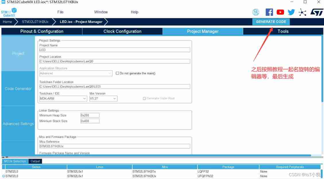
1、 open STM32CubeMX New project 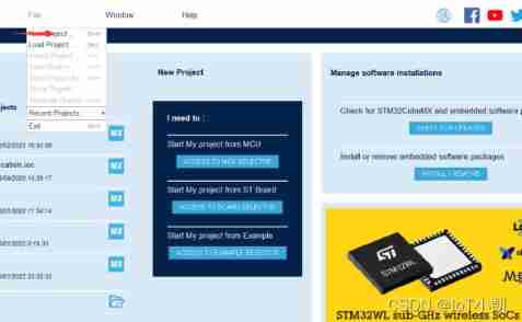
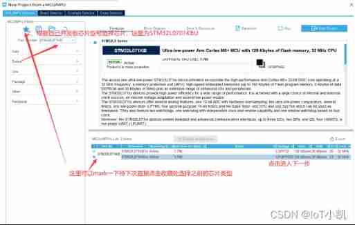
2、 Choose the chip model according to your chip type ( Here is STM32L071KBUx)
3、 Choose the clock
Since there is no need to consider accuracy ( After that, we need to consider the detailed setting of crystal oscillator ), Directly set 24M Crystal oscillator ( Any size , You can also enter 32M)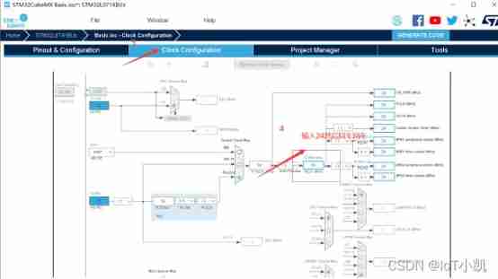
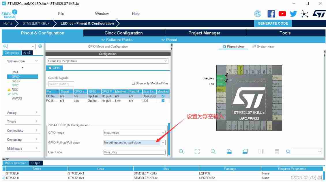
4、 Set up GPIO The input mode (User Key control LD5 Light out )
Add PC14 User Port pin control LD5 On and off , Set to input mode , Other unchanged generated files 
5、 Edit code 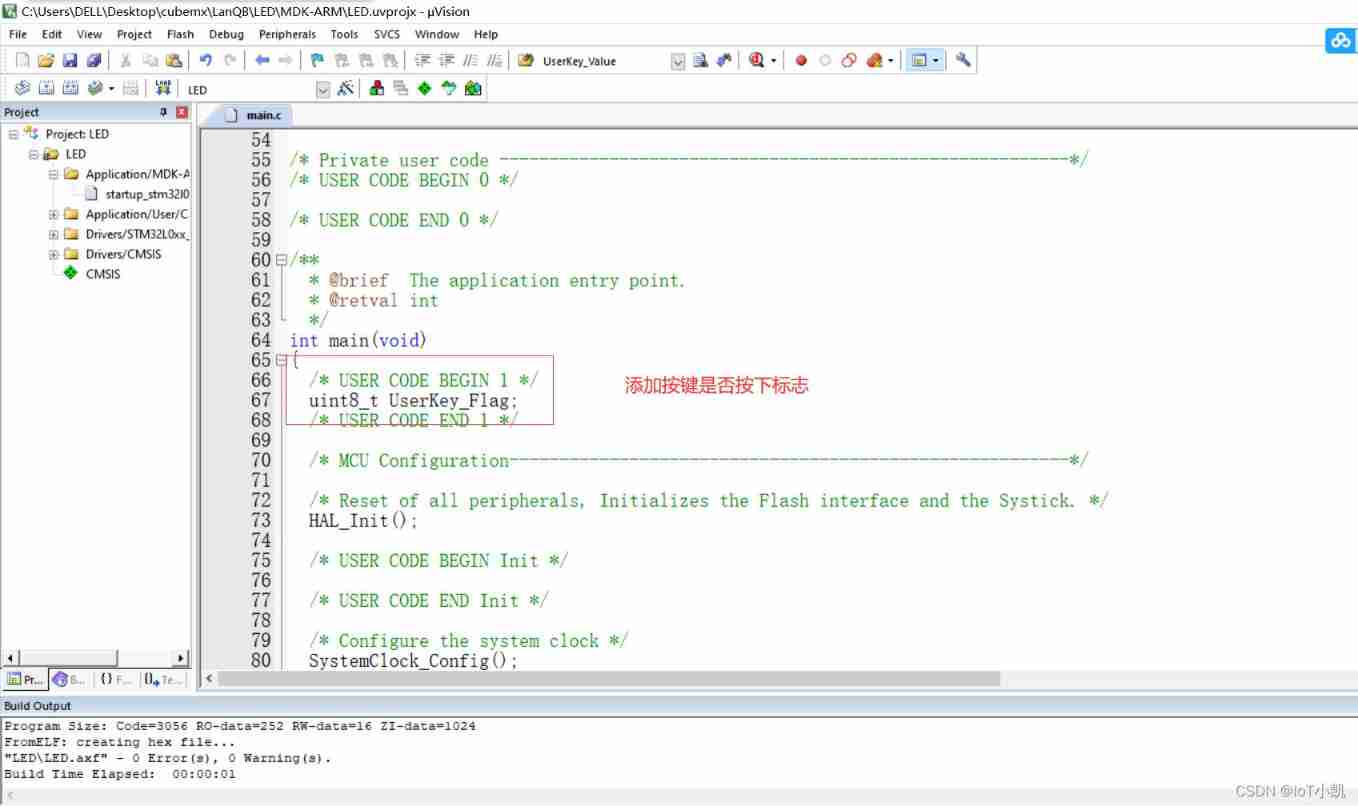
main.c Code :
/* USER CODE BEGIN Header */
/** ****************************************************************************** * @file : main.c * @brief : Main program body ****************************************************************************** * @attention * * <h2><center>© Copyright (c) 2022 STMicroelectronics. * All rights reserved.</center></h2> * * This software component is licensed by ST under BSD 3-Clause license, * the "License"; You may not use this file except in compliance with the * License. You may obtain a copy of the License at: * opensource.org/licenses/BSD-3-Clause * ****************************************************************************** */
/* USER CODE END Header */
/* Includes ------------------------------------------------------------------*/
#include "main.h"
#include "gpio.h"
/* Private includes ----------------------------------------------------------*/
/* USER CODE BEGIN Includes */
/* USER CODE END Includes */
/* Private typedef -----------------------------------------------------------*/
/* USER CODE BEGIN PTD */
/* USER CODE END PTD */
/* Private define ------------------------------------------------------------*/
/* USER CODE BEGIN PD */
/* USER CODE END PD */
/* Private macro -------------------------------------------------------------*/
/* USER CODE BEGIN PM */
/* USER CODE END PM */
/* Private variables ---------------------------------------------------------*/
/* USER CODE BEGIN PV */
/* USER CODE END PV */
/* Private function prototypes -----------------------------------------------*/
void SystemClock_Config(void);
/* USER CODE BEGIN PFP */
/* USER CODE END PFP */
/* Private user code ---------------------------------------------------------*/
/* USER CODE BEGIN 0 */
/* USER CODE END 0 */
/** * @brief The application entry point. * @retval int */
int main(void)
{
/* USER CODE BEGIN 1 */
uint8_t UserKey_Flag; // Key symbol
/* USER CODE END 1 */
/* MCU Configuration--------------------------------------------------------*/
/* Reset of all peripherals, Initializes the Flash interface and the Systick. */
HAL_Init();
/* USER CODE BEGIN Init */
/* USER CODE END Init */
/* Configure the system clock */
SystemClock_Config();
/* USER CODE BEGIN SysInit */
/* USER CODE END SysInit */
/* Initialize all configured peripherals */
MX_GPIO_Init();
/* USER CODE BEGIN 2 */
/* USER CODE END 2 */
/* Infinite loop */
/* USER CODE BEGIN WHILE */
while (1)
{
/* USER CODE END WHILE */
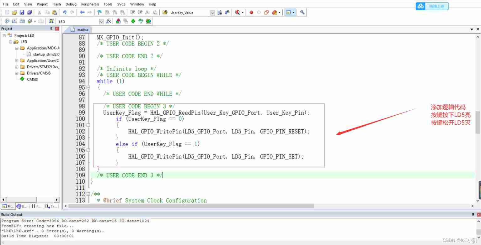
/* USER CODE BEGIN 3 */
UserKey_Flag = HAL_GPIO_ReadPin(User_Key_GPIO_Port, User_Key_Pin); // Read PC14 Pin level
if (UserKey_Flag == 0)
{
HAL_GPIO_WritePin(LD5_GPIO_Port, LD5_Pin, GPIO_PIN_RESET);// If the reading is low , Press the key ,LD5 bright
}
else if (UserKey_Flag == 1)// If it's high level , Release the key User, be LD5 Extinguish
{
HAL_GPIO_WritePin(LD5_GPIO_Port, LD5_Pin, GPIO_PIN_SET);
}
}
/* USER CODE END 3 */
}
/** * @brief System Clock Configuration * @retval None */
void SystemClock_Config(void)
{
RCC_OscInitTypeDef RCC_OscInitStruct = {
0};
RCC_ClkInitTypeDef RCC_ClkInitStruct = {
0};
/** Configure the main internal regulator output voltage */
__HAL_PWR_VOLTAGESCALING_CONFIG(PWR_REGULATOR_VOLTAGE_SCALE1);
/** Initializes the RCC Oscillators according to the specified parameters * in the RCC_OscInitTypeDef structure. */
RCC_OscInitStruct.OscillatorType = RCC_OSCILLATORTYPE_HSI;
RCC_OscInitStruct.HSIState = RCC_HSI_ON;
RCC_OscInitStruct.HSICalibrationValue = RCC_HSICALIBRATION_DEFAULT;
RCC_OscInitStruct.PLL.PLLState = RCC_PLL_ON;
RCC_OscInitStruct.PLL.PLLSource = RCC_PLLSOURCE_HSI;
RCC_OscInitStruct.PLL.PLLMUL = RCC_PLLMUL_3;
RCC_OscInitStruct.PLL.PLLDIV = RCC_PLLDIV_2;
if (HAL_RCC_OscConfig(&RCC_OscInitStruct) != HAL_OK)
{
Error_Handler();
}
/** Initializes the CPU, AHB and APB buses clocks */
RCC_ClkInitStruct.ClockType = RCC_CLOCKTYPE_HCLK|RCC_CLOCKTYPE_SYSCLK
|RCC_CLOCKTYPE_PCLK1|RCC_CLOCKTYPE_PCLK2;
RCC_ClkInitStruct.SYSCLKSource = RCC_SYSCLKSOURCE_PLLCLK;
RCC_ClkInitStruct.AHBCLKDivider = RCC_SYSCLK_DIV1;
RCC_ClkInitStruct.APB1CLKDivider = RCC_HCLK_DIV1;
RCC_ClkInitStruct.APB2CLKDivider = RCC_HCLK_DIV1;
if (HAL_RCC_ClockConfig(&RCC_ClkInitStruct, FLASH_LATENCY_1) != HAL_OK)
{
Error_Handler();
}
}
/* USER CODE BEGIN 4 */
/* USER CODE END 4 */
/** * @brief This function is executed in case of error occurrence. * @retval None */
void Error_Handler(void)
{
/* USER CODE BEGIN Error_Handler_Debug */
/* User can add his own implementation to report the HAL error return state */
__disable_irq();
while (1)
{
}
/* USER CODE END Error_Handler_Debug */
}
#ifdef USE_FULL_ASSERT
/** * @brief Reports the name of the source file and the source line number * where the assert_param error has occurred. * @param file: pointer to the source file name * @param line: assert_param error line source number * @retval None */
void assert_failed(uint8_t *file, uint32_t line)
{
/* USER CODE BEGIN 6 */
/* User can add his own implementation to report the file name and line number, ex: printf("Wrong parameters value: file %s on line %d\r\n", file, line) */
/* USER CODE END 6 */
}
#endif /* USE_FULL_ASSERT */
/************************ (C) COPYRIGHT STMicroelectronics *****END OF FILE****/
The phenomenon :
User Press the key ,LD5 Lighten up
User Release the button ,LD5 Extinguish
边栏推荐
- Semiconductor devices (III) FET
- VESC Benjamin test motor parameters
- H264 (I) i/p/b frame gop/idr/ and other parameters
- Live555 push RTSP audio and video stream summary (I) cross compilation
- Shell script
- 關於線性穩壓器的五個設計細節
- Array integration initialization (C language)
- Weidongshan Internet of things learning lesson 1
- Measurement fitting based on Halcon learning [II] meaure_ pin. Hdev routine
- 实例008:九九乘法表
猜你喜欢
Sword finger offer 09 Implementing queues with two stacks

如何写Cover Letter?
Summary -st2.0 Hall angle estimation
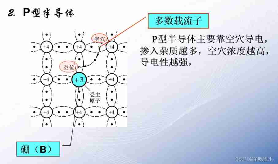
Semiconductor devices (I) PN junction
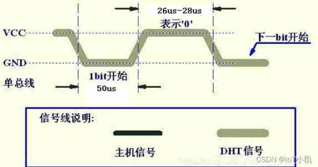
STM32 summary (HAL Library) - DHT11 temperature sensor (intelligent safety assisted driving system)

MHA High available Cluster for MySQL
![[tutorial 19 of trio basic from introduction to proficiency] detailed introduction of trio as a slave station connecting to the third-party bus (anybus PROFIBUS DP...)](/img/54/2fe86f54af01f10de93818103f2154.jpg)
[tutorial 19 of trio basic from introduction to proficiency] detailed introduction of trio as a slave station connecting to the third-party bus (anybus PROFIBUS DP...)
剑指 Offer 05. 替换空格
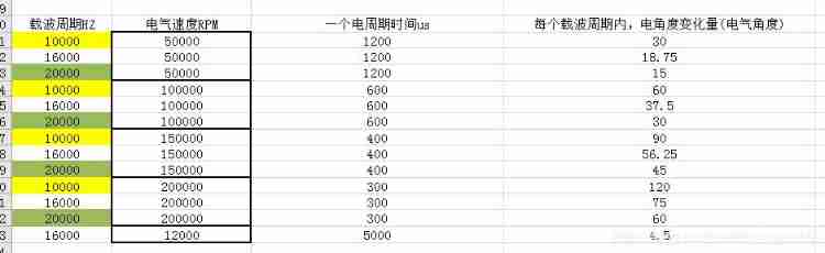
Carrier period, electrical speed, carrier period variation
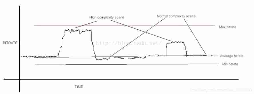
H264 (I) i/p/b frame gop/idr/ and other parameters
随机推荐
【论文阅读】2022年最新迁移学习综述笔注(Transferability in Deep Learning: A Survey)
亿学学堂给的证券账户安不安全?哪里可以开户
Adaptive filter
Bluebridge cup internet of things basic graphic tutorial - GPIO output control LD5 on and off
Let's briefly talk about the chips commonly used in mobile phones - OVP chips
Halcon's practice based on shape template matching [2]
Talk about the function of magnetic beads in circuits
实例004:这天第几天 输入某年某月某日,判断这一天是这一年的第几天?
Verilog -- state machine coding method
Negative pressure generation of buck-boost circuit
Introduction of air gap, etc
Vofa+ software usage record
2020-05-21
Volatile of C language
Naming rules for FreeRTOS
NTC thermistor application - temperature measurement
[trio basic tutorial 16 from introduction to proficiency] UDP communication test supplement
[tutorial 19 of trio basic from introduction to proficiency] detailed introduction of trio as a slave station connecting to the third-party bus (anybus PROFIBUS DP...)
DokuWiki deployment notes
Shell script