当前位置:网站首页>STM32 --- configuration of external interrupt
STM32 --- configuration of external interrupt
2022-07-05 08:15:00 【chen_ bx】
STM32--- Configuration of external interrupts
Sample functions
Use external interrupt , When you press the key 0 Trigger interrupt on when pressed LED0, When you press the key 1 Trigger interrupt on when pressed LED1, When you press the key 3 Trigger interrupt when pressed , close LED0 and LED1.
Configure external interrupt steps
① Set interrupt grouping
stay main Set interrupt grouping in function
NVIC_PriorityGroupConfig(NVIC_PriorityGroup_2);
② Turn on AFIO The clock
stay Exti_Init Enable in function AFIO The clock
RCC_APB2PeriphClockCmd(RCC_APB2Periph_AFIO,ENABLE);
③ initialization GPIO
example :
void KEY_Init(){


	GPIO_InitTypeDef GPIO_InitStructure;

	RCC_APB2PeriphClockCmd(RCC_APB2Periph_GPIOE,ENABLE);
	RCC_APB2PeriphClockCmd(RCC_APB2Periph_GPIOA,ENABLE);


	GPIO_InitStructure.GPIO_Mode=GPIO_Mode_IPU;
	GPIO_InitStructure.GPIO_Pin=GPIO_Pin_3|GPIO_Pin_4;
	GPIO_Init(GPIOE,&GPIO_InitStructure);

	GPIO_InitStructure.GPIO_Mode=GPIO_Mode_IPD;
	GPIO_InitStructure.GPIO_Pin=GPIO_Pin_0;
	GPIO_Init(GPIOA,&GPIO_InitStructure);

}
④ call Exti_Init Initialization function
EXTI_InitTypeDef The structure is as follows
typedef struct
{

  uint32_t EXTI_Line;               /*!< Specifies the EXTI lines to be enabled or disabled. This parameter can be any combination of @ref EXTI_Lines */

  EXTIMode_TypeDef EXTI_Mode;       /*!< Specifies the mode for the EXTI lines. This parameter can be a value of @ref EXTIMode_TypeDef */

  EXTITrigger_TypeDef EXTI_Trigger; /*!< Specifies the trigger signal active edge for the EXTI lines. This parameter can be a value of @ref EXTIMode_TypeDef */

  FunctionalState EXTI_LineCmd;     /*!< Specifies the new state of the selected EXTI lines. This parameter can be set either to ENABLE or DISABLE */
}EXTI_InitTypeDef;
Yes EXTI To initialize
example :
GPIO_EXTILineConfig(GPIO_PortSourceGPIOE,GPIO_PinSource3); // Set up IO Mapping relationship between port and interrupt line
EXTI_InitStructure.EXTI_Line=EXTI_Line3; // Configure interrupt line
EXTI_InitStructure.EXTI_LineCmd=ENABLE;		// Can make OR
EXTI_InitStructure.EXTI_Mode=EXTI_Mode_Interrupt; // Set the mode ; interrupt
EXTI_InitStructure.EXTI_Trigger=EXTI_Trigger_Falling;// Set the interrupt trigger mode
EXTI_Init(&EXTI_InitStructure);
⑤ Configure interrupt grouping , And can interrupt
example :
NVIC_InitStructure.NVIC_IRQChannel = EXTI0_IRQn;			// Enable key WK_UP External interrupt channel
NVIC_InitStructure.NVIC_IRQChannelPreemptionPriority = 2;	// preemption 2,
NVIC_InitStructure.NVIC_IRQChannelSubPriority = 2;					// Sub priority 2
NVIC_InitStructure.NVIC_IRQChannelCmd = ENABLE;								// Enable external interrupt channels
NVIC_Init(&NVIC_InitStructure);
⑥ Write interrupt service function
example :
void EXTI0_IRQHandler(void){

	delay(10);// Desquamation
	if(KEY_UP==1)	 	 //WK_UP Key
	{

		LED0_OFF; // close LED0
		LED1_OFF; // close LED1
	}
	EXTI_ClearITPendingBit(EXTI_Line0); // eliminate LINE0 Interrupt flag bit on
}
Complete code
main The function code is as follows :
#include "stm32f10x.h"
#include "led.h"
#include "sys.h"
#include "key.h"
#include "exti.h"

int main(void){

	NVIC_PriorityGroupConfig(NVIC_PriorityGroup_2);
	LED_Init();
	Exti_Init();
	while(1);
}
led.c The code is as follows :
#include "led.h"
#include "stm32f10x.h"

void LED_Init(){


	GPIO_InitTypeDef GPIO_InitStructure;

	RCC_APB2PeriphClockCmd(RCC_APB2Periph_GPIOB,ENABLE);
	RCC_APB2PeriphClockCmd(RCC_APB2Periph_GPIOE,ENABLE);

	GPIO_InitStructure.GPIO_Mode=GPIO_Mode_Out_PP;
	GPIO_InitStructure.GPIO_Pin=GPIO_Pin_5;
	GPIO_InitStructure.GPIO_Speed=GPIO_Speed_50MHz;
	GPIO_Init(GPIOB,&GPIO_InitStructure);
	GPIO_SetBits(GPIOB,GPIO_Pin_5);

	GPIO_InitStructure.GPIO_Mode=GPIO_Mode_Out_PP;
	GPIO_InitStructure.GPIO_Pin=GPIO_Pin_5;
	GPIO_InitStructure.GPIO_Speed=GPIO_Speed_50MHz;
	GPIO_Init(GPIOE,&GPIO_InitStructure);
	GPIO_SetBits(GPIOE,GPIO_Pin_5);
}
led.h The code is as follows :
#ifndef __LED_H
#define __LED_H

void LED_Init(void);

#define LED0_ON GPIO_ResetBits(GPIOB,GPIO_Pin_5);
#define LED0_OFF GPIO_SetBits(GPIOB,GPIO_Pin_5);

#define LED1_ON GPIO_ResetBits(GPIOE,GPIO_Pin_5);
#define LED1_OFF GPIO_SetBits(GPIOE,GPIO_Pin_5);

#endif
key.c The code is as follows :
#include "key.h"
#include "stm32f10x.h"

void KEY_Init(){


	GPIO_InitTypeDef GPIO_InitStructure;

	RCC_APB2PeriphClockCmd(RCC_APB2Periph_GPIOE,ENABLE);
	RCC_APB2PeriphClockCmd(RCC_APB2Periph_GPIOA,ENABLE);


	GPIO_InitStructure.GPIO_Mode=GPIO_Mode_IPU;
	GPIO_InitStructure.GPIO_Pin=GPIO_Pin_3|GPIO_Pin_4;
	GPIO_Init(GPIOE,&GPIO_InitStructure);

	GPIO_InitStructure.GPIO_Mode=GPIO_Mode_IPD;
	GPIO_InitStructure.GPIO_Pin=GPIO_Pin_0;
	GPIO_Init(GPIOA,&GPIO_InitStructure);

}
key.h The code is as follows :
#ifndef __KEY_H
#define __KEY_H


#define KEY0 GPIO_ReadInputDataBit(GPIOE,GPIO_Pin_3)
#define KEY1 GPIO_ReadInputDataBit(GPIOE,GPIO_Pin_4)
#define KEY_UP GPIO_ReadInputDataBit(GPIOA,GPIO_Pin_0)
void KEY_Init(void);

#endif
exti.c The code is as follows
#include "exti.h"
#include "key.h"
#include "led.h"
#include "stm32f10x.h"

void delay(int len)
{

	volatile unsigned int i = 7200*len;
	while(i--);
}

void Exti_Init(){

	EXTI_InitTypeDef EXTI_InitStructure;
	NVIC_InitTypeDef NVIC_InitStructure;
	RCC_APB2PeriphClockCmd(RCC_APB2Periph_AFIO,ENABLE); // Can make AFIO The clock

	KEY_Init(); // Key initialization (GPIO initialization )

	GPIO_EXTILineConfig(GPIO_PortSourceGPIOE,GPIO_PinSource3); // Set up IO Mapping relationship between port and interrupt line
	EXTI_InitStructure.EXTI_Line=EXTI_Line3; // Configure interrupt line
	EXTI_InitStructure.EXTI_LineCmd=ENABLE;		// Can make OR
	EXTI_InitStructure.EXTI_Mode=EXTI_Mode_Interrupt; // Set the mode ; interrupt
	EXTI_InitStructure.EXTI_Trigger=EXTI_Trigger_Falling;// Set the interrupt trigger mode
	EXTI_Init(&EXTI_InitStructure);

	GPIO_EXTILineConfig(GPIO_PortSourceGPIOE,GPIO_PinSource4);
	EXTI_InitStructure.EXTI_Line=EXTI_Line4;
	EXTI_InitStructure.EXTI_LineCmd=ENABLE;
	EXTI_InitStructure.EXTI_Mode=EXTI_Mode_Interrupt;
	EXTI_InitStructure.EXTI_Trigger=EXTI_Trigger_Falling;
	EXTI_Init(&EXTI_InitStructure);

	GPIO_EXTILineConfig(GPIO_PortSourceGPIOA,GPIO_PinSource0);
	EXTI_InitStructure.EXTI_Line=EXTI_Line0;
	EXTI_InitStructure.EXTI_LineCmd=ENABLE;
	EXTI_InitStructure.EXTI_Mode=EXTI_Mode_Interrupt;
	EXTI_InitStructure.EXTI_Trigger=EXTI_Trigger_Rising;
	EXTI_Init(&EXTI_InitStructure);

	NVIC_InitStructure.NVIC_IRQChannel=EXTI3_IRQn;
	NVIC_InitStructure.NVIC_IRQChannelCmd=ENABLE;
	NVIC_InitStructure.NVIC_IRQChannelPreemptionPriority=1;
	NVIC_InitStructure.NVIC_IRQChannelSubPriority=2;
	NVIC_Init(&NVIC_InitStructure);

	NVIC_InitStructure.NVIC_IRQChannel=EXTI4_IRQn;
	NVIC_InitStructure.NVIC_IRQChannelCmd=ENABLE;
	NVIC_InitStructure.NVIC_IRQChannelPreemptionPriority=1;
	NVIC_InitStructure.NVIC_IRQChannelSubPriority=2;
	NVIC_Init(&NVIC_InitStructure);

	NVIC_InitStructure.NVIC_IRQChannel = EXTI0_IRQn;			// Enable key WK_UP External interrupt channel
  	NVIC_InitStructure.NVIC_IRQChannelPreemptionPriority = 2;	// preemption 2,
  	NVIC_InitStructure.NVIC_IRQChannelSubPriority = 2;					// Sub priority 2
  	NVIC_InitStructure.NVIC_IRQChannelCmd = ENABLE;								// Enable external interrupt channels
  	NVIC_Init(&NVIC_InitStructure);
}

void EXTI0_IRQHandler(void){

	delay(10);// Desquamation
	if(KEY_UP==1)	 	 //WK_UP Key
	{

		LED0_OFF; // close LED0
		LED1_OFF; // close LED1
	}
	EXTI_ClearITPendingBit(EXTI_Line0); // eliminate LINE0 Interrupt flag bit on
}

void EXTI3_IRQHandler(void){

		delay(10);// Desquamation
	if(KEY0==0)	 	 //KEY0 Key
	{

		LED0_ON; // open LED0
	}
	EXTI_ClearITPendingBit(EXTI_Line3); // eliminate LINE3 Interrupt flag bit on
}


void EXTI4_IRQHandler(void){

	delay(10);// Desquamation
	if(KEY1==0)	 	 //KEY1 Key
	{

		LED1_ON;     // open LED1
	}
	EXTI_ClearITPendingBit(EXTI_Line4); // eliminate LINE4 Interrupt flag bit on
}
exti.h The code is as follows :
#ifndef __EXTI_H
#define __EXTI_H

void Exti_Init(void);

#endif
边栏推荐
- Solutions to compilation warnings in Quartus II
- [trio basic tutorial 18 from introduction to proficiency] trio motion controller UDP fast exchange data communication
- Process communication mode between different hosts -- socket
- Volatile of C language
- Circleq of linked list
- UEFI development learning series
- Step motor generates S-curve upper computer
- 【论文阅读】2022年最新迁移学习综述笔注(Transferability in Deep Learning: A Survey)
- Consul installation
- Synchronization of QT multithreading
猜你喜欢
Factors affecting the quality of slip rings in production
Process communication mode between different hosts -- socket
After installing the new version of keil5 or upgrading the JLINK firmware, you will always be prompted about the firmware update
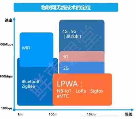
Nb-iot technical summary
Arduino uses nrf24l01+ communication
My-basic application 2: my-basic installation and operation
List of linked lists
Briefly talk about the identification protocol of mobile port -bc1.2
Basic embedded concepts
DokuWiki deployment notes
随机推荐
Hardware and software solution of FPGA key chattering elimination
Sizeof (function name) =?
Bluetooth hc-05 pairing process and precautions
[trio basic from introduction to mastery tutorial XIV] trio realizes unit axis multi-color code capture
Stablq of linked list
Explain task scheduling based on Cortex-M3 in detail (Part 2)
Summary of SIM card circuit knowledge
Classic application of MOS transistor circuit design (2) - switch circuit design
Soem EtherCAT source code analysis attachment 1 (establishment of communication operation environment)
[paper reading] the latest transfer ability in deep learning: a survey in 2022
Charge pump boost principle - this article will give you a simple understanding
Halcon's practice based on shape template matching [1]
STM32 virtualization environment of QEMU
Measurement fitting based on Halcon learning [III] PM_ measure_ board. Hdev routine
Improve lighting C program
VESC Benjamin test motor parameters
MySQL之MHA高可用集群
Gradle复合构建
Zero length array in GNU C
Hardware 1 -- relationship between gain and magnification