当前位置:网站首页>STM32 --- serial port communication
STM32 --- serial port communication
2022-07-05 08:16:00 【chen_ bx】
STM32--- Serial port communication
Light up through serial port communication LED The lamp
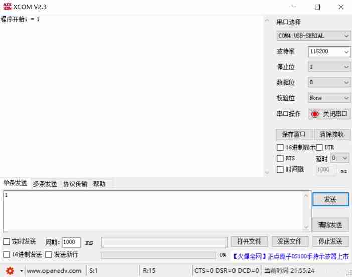
Realize sending through serial port ’1’ Light up the red light , send out ’2’ Turn on the yellow light , send out ‘3’ Turn on all lights , Send other data and turn off all lights .
Basic serial port configuration
No need to interrupt , So the interrupt code in the code is commented out .
usart.h The code is as follows :
#ifndef __USART_H
#define __USART_H
#include "stm32f10x.h"

void Usart_Init(void);
void Usart_SendByte(USART_TypeDef* pUSARTx,uint8_t data);

#endif /* USART_H */
usart.c The code is as follows :
#include "usart.h"
#include "stm32f10x.h"
#include "stdio.h"

//static void Nvic_Init(){

// NVIC_InitTypeDef NVIC_InitStructure;
// NVIC_PriorityGroupConfig(NVIC_PriorityGroup_2);
//
// NVIC_InitStructure.NVIC_IRQChannel=USART1_IRQn;
// NVIC_InitStructure.NVIC_IRQChannelPreemptionPriority=1;
// NVIC_InitStructure.NVIC_IRQChannelSubPriority=1;
// NVIC_InitStructure.NVIC_IRQChannelCmd=ENABLE;
// NVIC_Init(&NVIC_InitStructure);
//}


void Usart_Init(){

	GPIO_InitTypeDef GPIO_InitStructure;
	USART_InitTypeDef USART_InitStructure;

	// open IO The clock
	RCC_APB2PeriphClockCmd(RCC_APB2Periph_GPIOA,ENABLE);
	RCC_APB2PeriphClockCmd(RCC_APB2Periph_USART1,ENABLE);

	// send out
	GPIO_InitStructure.GPIO_Pin=GPIO_Pin_9;
	GPIO_InitStructure.GPIO_Mode=GPIO_Mode_AF_PP;
	GPIO_InitStructure.GPIO_Speed=GPIO_Speed_50MHz;
	GPIO_Init(GPIOA,&GPIO_InitStructure);

	// Accept
	GPIO_InitStructure.GPIO_Pin=GPIO_Pin_10;
	GPIO_InitStructure.GPIO_Mode=GPIO_Mode_IN_FLOATING;
	GPIO_Init(GPIOA,&GPIO_InitStructure);

	// Interrupt priority configuration
// Nvic_Init();

	// Serial port configuration
	USART_InitStructure.USART_BaudRate=115200;
	USART_InitStructure.USART_HardwareFlowControl=USART_HardwareFlowControl_None;
	USART_InitStructure.USART_Mode=USART_Mode_Tx|USART_Mode_Rx;
	USART_InitStructure.USART_Parity=USART_Parity_No;
	USART_InitStructure.USART_StopBits=USART_StopBits_1;
	USART_InitStructure.USART_WordLength=USART_WordLength_8b;
	USART_Init(USART1,&USART_InitStructure);

// USART_ITConfig(USART1,USART_IT_RXNE,ENABLE);

	USART_Cmd(USART1,ENABLE);
}

// send data
//void Usart_SendByte(USART_TypeDef* pUSARTx,uint8_t data){

// USART_SendData(pUSARTx,data);
// while( USART_GetFlagStatus(pUSARTx,USART_FLAG_TXE) == RESET);
//
//}

// Interrupt service function
//void USART1_IRQHandler(){

// uint8_t text;
// if(USART_GetITStatus(USART1,USART_IT_RXNE)!=RESET ){

// text = USART_ReceiveData(USART1);
//
// USART_SendData(USART1,text);
// }

//}

// redefinition fputc function
// printf Function redirection
int fputc(int ch, FILE *f)
{

	USART_SendData(USART1,(uint8_t) ch);
	while( USART_GetFlagStatus(USART1,USART_FLAG_TXE) == RESET);
	return (ch);
}
//getchar Function redirection
int fgetc(FILE *f)
{

	while( USART_GetFlagStatus(USART1,USART_FLAG_RXNE) == RESET);
	return (int)USART_ReceiveData(USART1);
}
main function code
#include "stm32f10x.h"
#include "led.h"
#include "usart.h"
#include <stdio.h>

int main(void)
{

	uint8_t i;
	Usart_Init();
	LED_Init();
	//Usart_SendByte(USART1,100);
	//USART_SendData(USART1,100);
	printf(" Program starts \n");
	while(1){

		i = getchar();
		printf("i = %c\n",i);

		switch(i){

			case '1':
				LED_RED_TOGGLE;
				break;
			case '2':
				LED_YELLOW_TOGGLE;
				break;
			case '3':
				LED_RED_ON;
				LED_YELLOW_ON;
				break;
			default:
				LED_RED_OFF;
				LED_YELLOW_OFF;
				break;
		}
	}
}
Serial debugging assistant
Be careful
1. You need to check Target => Use MicroLIB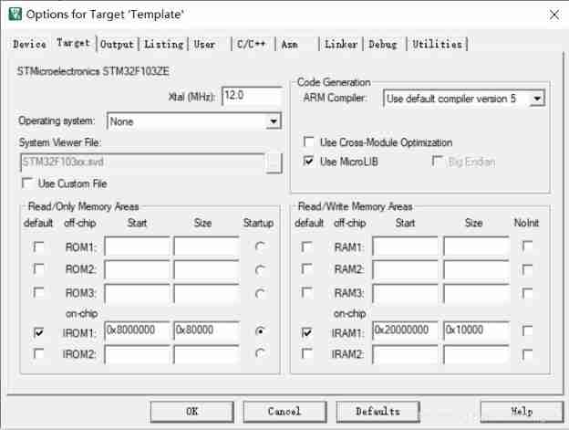
2. If serial assistant is not checked 16 Base number All data sent and received are characters .
边栏推荐
- Summary of SIM card circuit knowledge
- C language enhancement -- pointer
- Void* C is a carrier for realizing polymorphism
- 亿学学堂给的证券账户安不安全?哪里可以开户
- DCDC circuit - function of bootstrap capacitor
- Keil use details -- magic wand
- Soem EtherCAT source code analysis I (data type definition)
- Shape template matching based on Halcon learning [viii] PM_ multiple_ models. Hdev routine
- C WinForm [view status bar -- statusstrip] - Practice 2
- Some thoughts on extracting perspectives from ealfa and Ebeta
猜你喜欢
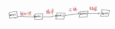
Development tools -- gcc compiler usage
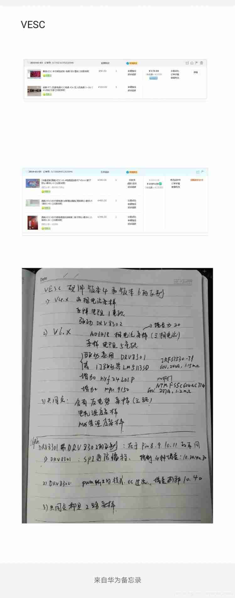
VESC Benjamin test motor parameters
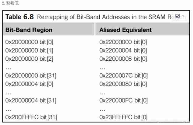
STM32 single chip microcomputer - bit band operation
![C WinForm [change the position of the form after running] - Practical Exercise 4](/img/f7/ddaf5773295ca6929d39d7aa760d36.jpg)
C WinForm [change the position of the form after running] - Practical Exercise 4

MySQL MHA high availability cluster
Summary -st2.0 Hall angle estimation
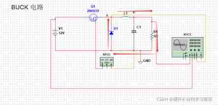
Brief discussion on Buck buck circuit
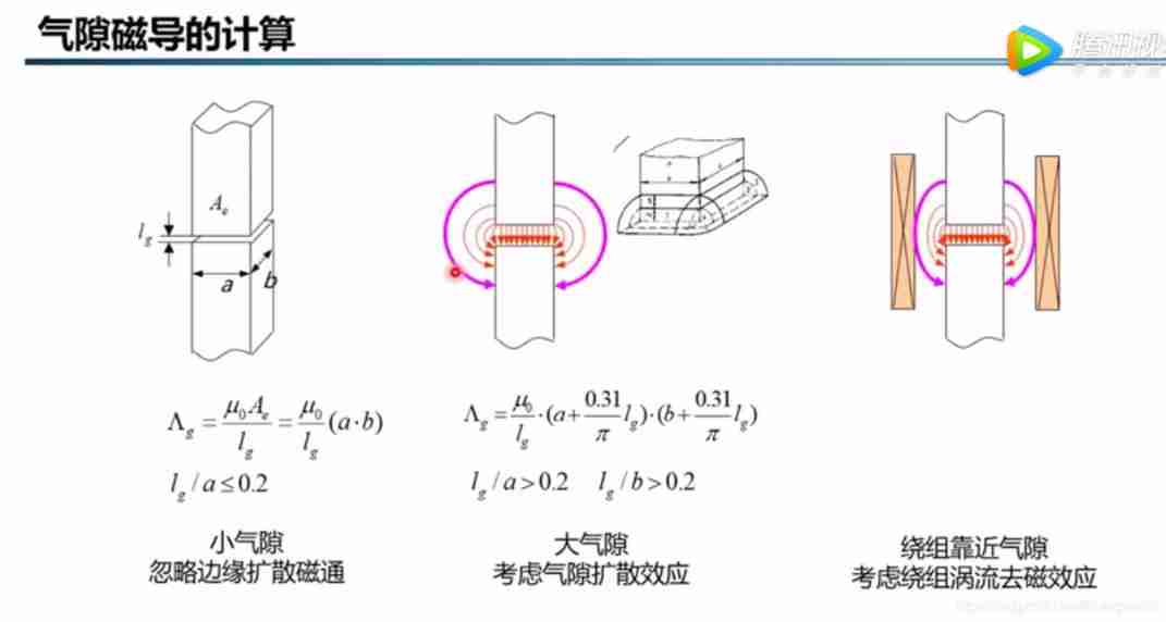
Introduction of air gap, etc
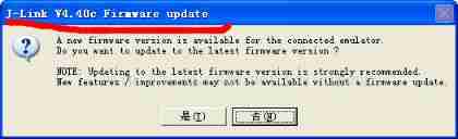
After installing the new version of keil5 or upgrading the JLINK firmware, you will always be prompted about the firmware update
QEMU STM32 vscode debugging environment configuration
随机推荐
Relationship between line voltage and phase voltage, line current and phase current
Sql Server的存儲過程詳解
Why is 1900 not a leap year
C WinForm [exit application] - practice 3
Step motor generates S-curve upper computer
Briefly talk about the identification protocol of mobile port -bc1.2
QEMU STM32 vscode debugging environment configuration
MySQL之MHA高可用集群
Zero length array in GNU C
Basic information commands and functions of kernel development
Consul installation
STM32 single chip microcomputer -- volatile keyword
[paper reading] the latest transfer ability in deep learning: a survey in 2022
Management and use of DokuWiki (supplementary)
Wifi-802.11 negotiation rate table
Detailed explanation of pragma usage
Live555 RTSP audio and video streaming summary (II) modify RTSP server streaming URL address
go依赖注入--google开源库wire
Class of color image processing based on Halcon learning_ ndim_ norm. hdev
Programming knowledge -- basis of C language