当前位置:网站首页>Several implementation schemes of anti reverse connection protection of positive and negative poles of power supply!
Several implementation schemes of anti reverse connection protection of positive and negative poles of power supply!
2022-07-05 08:06:00 【Learning notes of hardware Xiaobai】
Anti reverse connection of power supply , It should be that this series of designs will be adopted in many circuit scenarios .
A few days ago , Xiaobai is doing board verification , When the dummy battery is connected and the power is supplied , Accidentally connect the positive and negative poles of the fake battery with the input and output of the power supply , Cause the board to burn , In an instant, a wisp of smoke floated on my seat . Because our products use real batteries , So there will be no reverse connection , There is no design to prevent reverse connection of power supply , But it is in the stage of debugging and verification , True battery Limited , So the fake battery is used , So ,,, I can't help but feel the above situation .
Based on this question , today , I still want to sort it out simply , In some circuits , Circuit measures taken to prevent reverse connection of power supply .
- Diode series reverse connection protection circuit
At the input of the power supply , Connect a forward diode in series , It mainly uses the forward conduction of the diode , Characteristics of reverse cut-off .
When the circuit is connected normally , The diode is on , The circuit can work normally .
When the power supply is connected reversely , Diode cut off , The power supply cannot form a loop , The circuit board does not work properly , It can effectively prevent the harm caused by reverse connection .
But here's the thing , There is a voltage drop in the diode . The diode voltage drop of silicon material is generally 0.7V. The diode voltage drop of germanium material is generally 0.3V.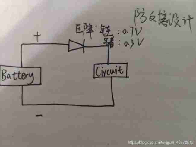
- Use bridge rectifier circuit to prevent reverse connection protection circuit
Use bridge rectifier circuit , Whether the power supply is connected directly or reversely , The circuit can work normally .
But there are the same problems as the first method , There is a voltage drop in the diode , It will cause the input voltage of the subsequent circuit to be less than the power supply voltage .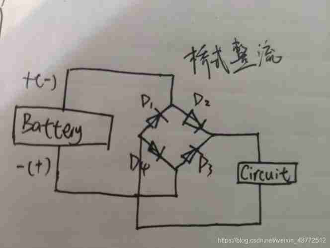
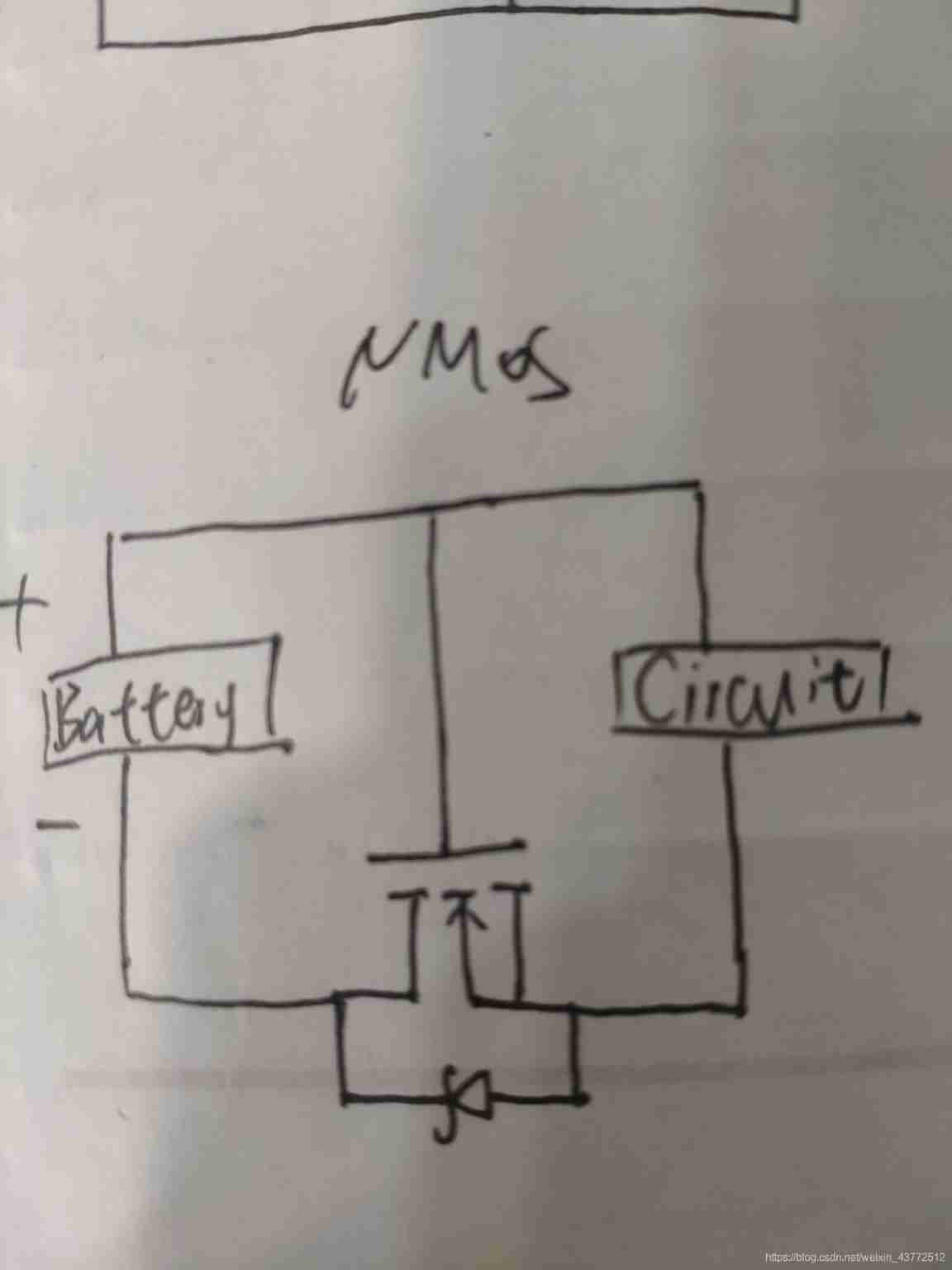
- Use MOS The tube is protected against reverse circuit
MOS The tube has conduction impedance , namely RDS(on)- Drain electrode / Conduction impedance between sources . So when designing this kind of circuit , Choose the one with smaller conduction impedance MOS tube . Generally, it is about a few milliohms or dozens of milliohms . At this time, the pressure drop is very small , Negligible .
(1) NMOS protective
In the moment of electricity ,MOS The parasitic diode of the tube turns on , The system constitutes a loop . The source voltage is about 0.6V. At this time, the grid voltage is Vbat,MOS The opening voltage of the tube Vgs=Vbat-0.6. As long as it is greater than the standard of the specification ,DS It can be connected , here MOS The parasitic diode of the tube is short circuited , The system goes through MOS Tubular DS Generate circuit .
If the power supply is reversed ,NMOS The conduction voltage of the tube is 0,NMOS end , Parasitic diode reverse connection , The circuit is disconnected , Unable to form a loop .
(2) PMOS protective ( It is recommended to use )
Similar to the above , At the moment of power on ,MOS The parasitic diode of the tube turns on , The system constitutes a loop , The source voltage is Vbat-0.6V, However, the grid voltage is 0,MOS The opening voltage of the tube is Ugs=0-(Vbat-0.6), The grid is low ,PMOS, Conduction , Parasitic diode is short circuited , The system goes through PMOS Of ds Connect to form a loop .
If the power supply is connected reversely ,NMOS The on voltage of is greater than 0V,PMOS end , Parasitic diode reverse connection , The circuit is disconnected , Thus forming protection .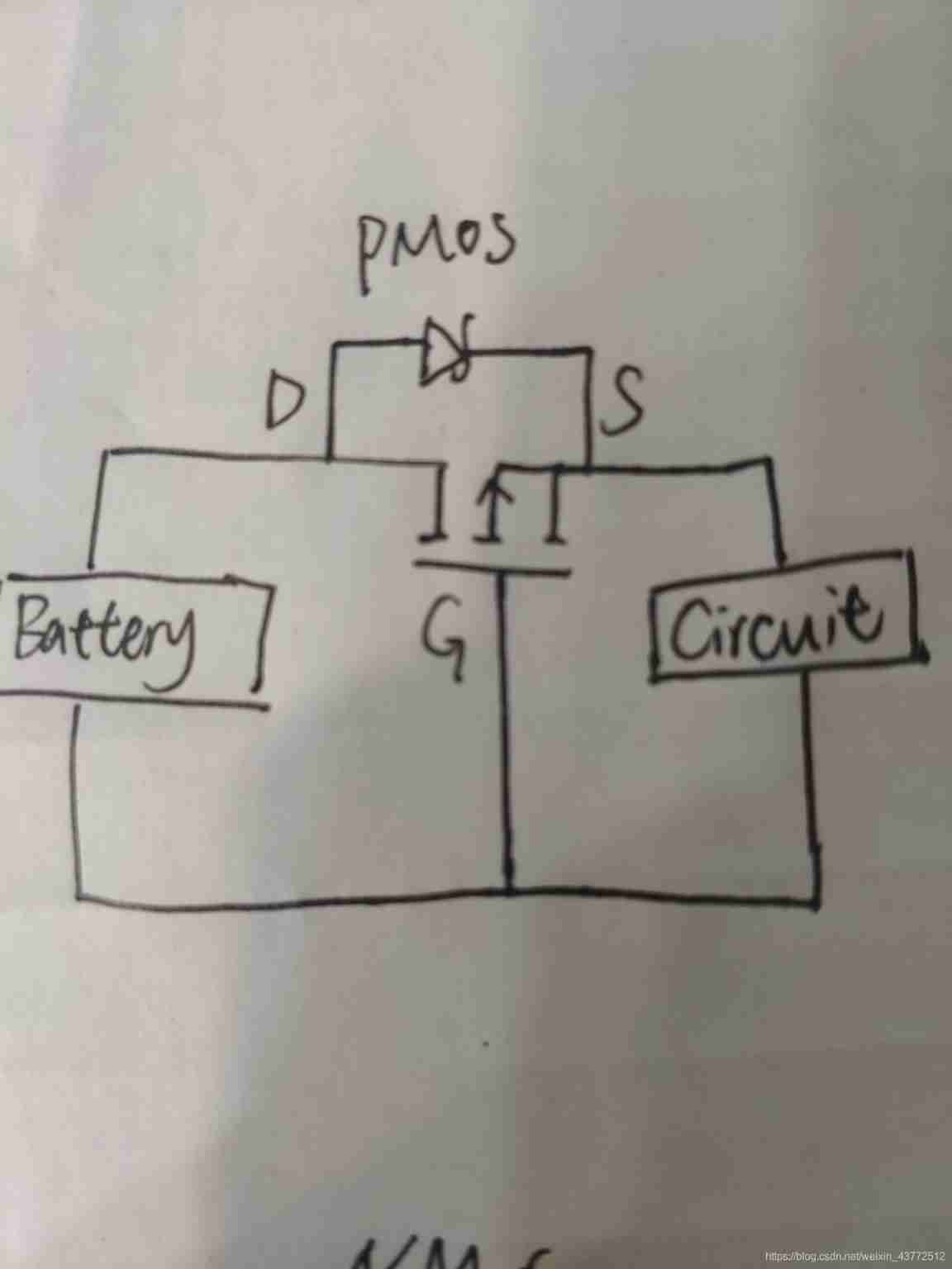
among ,NMOS Connected in series to the negative pole ,PMOS Connected in series to the positive pole , The parasitic diode is oriented in the correct direction of current flow .
NMOS, The current flows from D Flow into the pole S Polar outflow .PMOS It is ,S Flow into the pole D Polar outflow .
Practical application ,G Generally, a resistor is connected in series , In order to prevent MOS Tube is broken down , You can also add a zener diode . Capacitance connected in parallel to the voltage divider , It has a soft start function . At the moment when the current begins to flow , Capacitor charging ,G The pole voltage is gradually established .
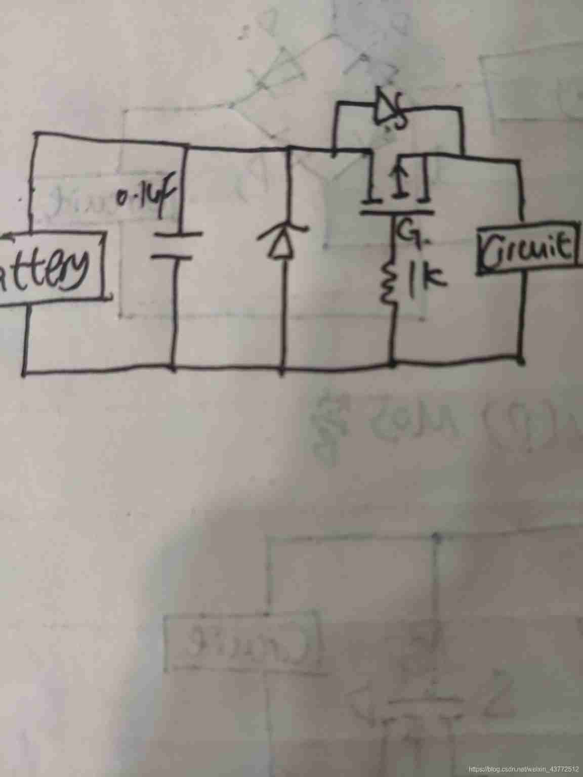
about PMOS, Compared with NMOS Conduction requires Vgs Greater than the threshold voltage , Because its opening voltage can be 0,DS The pressure difference between is not big , Than NMOS More advantages .
边栏推荐
- UEFI development learning 6 - creation of protocol
- Drive LED -- GPIO control
- MySQL blind note common functions
- C WinForm [exit application] - practice 3
- DokuWiki deployment notes
- Development tools -- gcc compiler usage
- Software designer: 03 database system
- Markdown tips
- Measurement fitting based on Halcon learning [II] meaure_ pin. Hdev routine
- C WinForm [view status bar -- statusstrip] - Practice 2
猜你喜欢
如何进行导电滑环选型
Drive LED -- GPIO control
Altium designer 19.1.18 - hide the fly line of a network

Consul安装
Design a clock frequency division circuit that can be switched arbitrarily
H264 (I) i/p/b frame gop/idr/ and other parameters
![[trio basic tutorial 18 from introduction to proficiency] trio motion controller UDP fast exchange data communication](/img/05/0f63e4cd3da24e5b956ec5899b939d.jpg)
[trio basic tutorial 18 from introduction to proficiency] trio motion controller UDP fast exchange data communication
Development tools -- gcc compiler usage

C # joint configuration with Halcon

Management and use of DokuWiki
随机推荐
生产中影响滑环质量的因素
[professional literacy] core conferences and periodicals in the field of integrated circuits
Altium designer learning (I)
如何进行导电滑环选型
[popular science] some interesting things that I don't know whether they are useful or not
Markdown tips
C WinForm [exit application] - practice 3
Soem EtherCAT source code analysis I (data type definition)
Anonymous structure in C language
Step motor generates S-curve upper computer
Detailed explanation of pragma usage
Altium designer 19.1.18 - hide the fly line of a network
Mlperf training v2.0 list released, with the same GPU configuration, the performance of Baidu PaddlePaddle ranks first in the world
UEFI development learning 3 - create UEFI program
IEEE access personal contribution experience record
研究發現,跨境電商客服系統都有這五點功能!
Shape template matching based on Halcon learning [VII] reuse_ model. Hdev routine
动力电池UL2580测试项目包括哪些
Explication de la procédure stockée pour SQL Server
[professional literacy] specific direction of analog integrated circuits