当前位置:网站首页>STM32 outputs 1PPS with adjustable phase
STM32 outputs 1PPS with adjustable phase
2022-07-05 08:10:00 【Nanbolwan】
When doing projects such as crystal oscillator punctuality, it is often necessary to generate a phase adjustable 1PPS, I recently encountered such a problem . utilize STM32 Timer of 1S, And then in TIM_IT_UPDATE Output when interrupt 1PPS The rising edge theory is ok , But it is inconvenient to move the phase , Modifying the count value of the timer is a method , But this will introduce a lot of systematic error .
utilize STM32 The output of the timer compares the mode output 1PPS And achieving the purpose of phase adjustment is the best method I think of at present , In fact, the principle of this mechanism is very simple .STM32 There are several registers in the timer of which we often use , They are :
- Prescaler register : Configuring it will divide the input main frequency of the timer . Suppose the dominant frequency of my system is 100M, The reference frequency of my timer is APB1 That is to say 50M, If I write 4, Then divide the frequency of the timer into 10M.
- Preload registers : This register will load the value of this register into the count register when the count register overflows .
- Count register : According to the example value of pre frequency division above , This register every 100ns The register value will be added until it reaches the preload value, and then an overflow interrupt will be generated .
- CCRx: When configured to compare output ,CCRx When the value in the register is equal to the value in the count register TIM_IT_CCRx interrupt .
	GPIO_InitTypeDef GPIO_InitStructure;
	TIM_TimeBaseInitTypeDef  TIM_TimeBaseStructure;
	TIM_OCInitTypeDef  TIM_OCInitStructure;
	NVIC_InitTypeDef NVIC_InitStructure;

	/* Set interrupt */
	NVIC_InitStructure.NVIC_IRQChannel = TIM3_IRQn;
	NVIC_InitStructure.NVIC_IRQChannelPreemptionPriority = 1;
	NVIC_InitStructure.NVIC_IRQChannelSubPriority = 1;
	NVIC_InitStructure.NVIC_IRQChannelCmd = ENABLE;
	NVIC_Init(&NVIC_InitStructure);

	/* The clock */
	RCC_APB1PeriphClockCmd(RCC_APB1Periph_TIM3, ENABLE);


   // initialization TIM3
	TIM_TimeBaseStructure.TIM_Period = 1000000-1; // Set the value of the auto reload register cycle for the next update event load activity
	TIM_TimeBaseStructure.TIM_Prescaler =72-1; //72 frequency division ,TIM3 = 1Mhz
	TIM_TimeBaseStructure.TIM_ClockDivision = TIM_CKD_DIV1; //1 frequency division
	TIM_TimeBaseStructure.TIM_CounterMode = TIM_CounterMode_Up;  // Upcount mode
	TIM_TimeBaseInit(TIM3, &TIM_TimeBaseStructure);


	// initialization TIM3 Channel2 PWM Pattern
	TIM_OCInitStructure.TIM_OCMode = TIM_OCMode_Toggle;
 	TIM_OCInitStructure.TIM_OutputState = TIM_OutputState_Enable; // Compare output enable
	TIM_OCInitStructure.TIM_OCPolarity = TIM_OCPolarity_High;

	TIM_OCInitStructure.TIM_Pulse = 1000000/2; //TIM3->CCR1 The initial value is 500000
	TIM_OC1Init(TIM3, &TIM_OCInitStructure);  // according to T The specified parameter initializes the peripheral TIM4 OC1
	TIM_ITConfig(TIM3, TIM_IT_CC1,ENABLE);
	TIM_SetCounter(TIM3,0);
The above configuration is the count register of the timer. The count value is from 0 Count to 999999, Because the clock frequency is just right 1M, So it happens to be every 1S The count value is cleared once . We set it to count to 5000000 A comparison output interrupt is generated . This cycle produces a 1PPS. We can adjust TIM3->CCR1 To adjust 1PPS The aspect of , The adjustment step is 1us.
void TIM3_IRQHandler(void)   //TIM3 interrupt
{

	if (TIM_GetITStatus(TIM3, TIM_IT_CC1) != RESET) // Check the specified TIM Whether the interruption occurs or not :TIM  Interrupt source
	{

		// Production here PPS the front
		TIM_ClearITPendingBit(TIM3, TIM_IT_CC1  );  // eliminate TIMx Interrupt pending bit of :TIM  Interrupt source
	}
}
边栏推荐
- 研究发现,跨境电商客服系统都有这五点功能!
- Nb-iot technical summary
- Record the torch encountered by win10 cuda. is_ False problem in available()
- Some thoughts on extracting perspectives from ealfa and Ebeta
- Let's briefly talk about the chips commonly used in mobile phones - OVP chips
- Embedded composition and route
- Create inf module in AMI code
- UEFI development learning 6 - creation of protocol
- C WinForm [get file path -- traverse folder pictures] - practical exercise 6
- PMSM dead time compensation
猜你喜欢
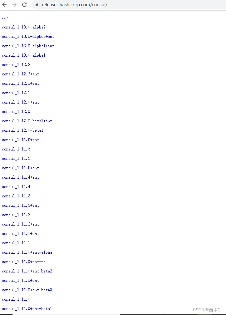
Consul安装
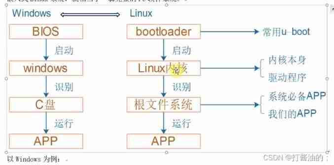
Embedded composition and route
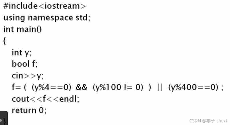
Why is 1900 not a leap year
![Shape template matching based on Halcon learning [viii] PM_ multiple_ models. Hdev routine](/img/13/22a1915329f58acd54c40176f6f301.jpg)
Shape template matching based on Halcon learning [viii] PM_ multiple_ models. Hdev routine
Shell脚本基本语法
如何将EasyCVR平台RTSP接入的设备数据迁移到EasyNVR中?
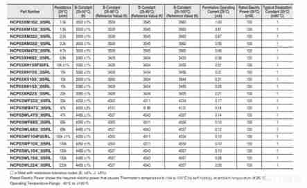
NTC thermistor application - temperature measurement
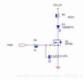
Classic application of MOS transistor circuit design (2) - switch circuit design
![[trio basic tutorial 18 from introduction to proficiency] trio motion controller UDP fast exchange data communication](/img/05/0f63e4cd3da24e5b956ec5899b939d.jpg)
[trio basic tutorial 18 from introduction to proficiency] trio motion controller UDP fast exchange data communication
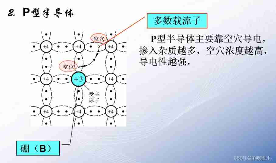
Semiconductor devices (I) PN junction
随机推荐
Working principle and type selection of common mode inductor
Connection mode - bridge and net
Shape template matching based on Halcon learning [vi] find_ mirror_ dies. Hdev routine
Random function usage notes
Design a clock frequency division circuit that can be switched arbitrarily
Communication standard -- communication protocol
[trio basic tutorial 16 from introduction to proficiency] UDP communication test supplement
PMSM dead time compensation
Fundamentals of C language
Reasons for rapid wear of conductive slip rings
Basic embedded concepts
Soem EtherCAT source code analysis II (list of known configuration information)
Compilation warning solution sorting in Quartus II
Detailed explanation of pragma usage
[trio basic tutorial 17 from getting started to mastering] set up and connect the trio motion controller and input the activation code
Shell script basic syntax
Explication de la procédure stockée pour SQL Server
Network communication model -- Network OSI tcp/ip layering
Semiconductor devices (I) PN junction
Screen record of the opening ceremony of the Beijing winter olympics 2