当前位置:网站首页>STC8H8K系列汇编和C51实战——数码管显示ADC、按键串口回复按键号与ADC数值
STC8H8K系列汇编和C51实战——数码管显示ADC、按键串口回复按键号与ADC数值
2022-07-02 05:52:00 【不知何人】
数码管显示ADC、串口显示ADC按键与数值
一、题目
实现了通过与通道ADC0相连的16个ADC按键引起的模拟电压信号变化的测量,用实验箱上的数码管高2位显示键码,低4位显示AD值。使用串口1在主机串口助手上显示键值和转换结果数值, 显示格式为: 键值:对应ADC结果。继续按键回车换行,以同样格式显示下一个键值及其ADC结果。
二、代码
main函数
//高2位显示键码,低4位显示AD值
#include<stc8h.h>
#include<intrins.h>
#define uchar unsigned char
#define uint unsigned int

bit busy;
u8 key=0;
uchar cnt1ms=0;
uint ad_volume=0;
#define ADC_OFFSET 64
uchar KeyCode=0;
void	CalculateAdcKey(uint adc);
uint	Get_ADC12bitResult(uchar channel);	//channel = 0~7

#define font_PORT P6 //定义字形码输出端口
#define position_PORT P7 //定义位控制码输出端口
uchar code  LED_SEG[]={
    0xc0,0xf9,0xa4,0xb0,0x99,0x92,0x82,0xf8,0x80,0x90,0x88,0x83,0xc6,0xa1,0x86,0x8e,0xff,0x40,0x79,0x24,0x30,0x19,0x12d,0x02,0x78,0x00,0x10,0xbf };
  //定义"0、1、2、3、4、5、6、7、8、9","A、B、C、D、E、F"以及"灭"的字形码
  //定义"0、1、2、3、4、5、6、7、8、9"(含小数点)的字符以及“-”的字形码
uchar code  Scan_bit[]={
    0xfe,0xfd,0xfb,0xf7,0xef,0xdf, 0xbf, 0x7f};   //定义扫描位控制码
uchar data  Dis_buf[]={
    16,16,16,16,16,16,16,0};   //定义显示缓冲区,最低位显示"0",其它为"灭"

void gpio()		//gpio初始化为准双向口,刚开始除了P30,P31其他均为高阻态
{

    P0M1 = 0x00;   P0M0 = 0x00;   //设置为准双向口
    P1M1 = 0x00;   P1M0 = 0x00;   //设置为准双向口
    P2M1 = 0x00;   P2M0 = 0x00;   //设置为准双向口
    P3M1 = 0x00;   P3M0 = 0x00;   //设置为准双向口
    P4M1 = 0x00;   P4M0 = 0x00;   //设置为准双向口
    P5M1 = 0x00;   P5M0 = 0x00;   //设置为准双向口
    P6M1 = 0x00;   P6M0 = 0x00;   //设置为准双向口
    P7M1 = 0x00;   P7M0 = 0x00;   //设置为准双向口
}


/*---------------------------- 发送字节 ----------------------------*/
void SendData(uchar dat)
{

    while (busy);
    busy = 1;
    SBUF = dat;                 //要发送的数据存入SBUF
}

/*---------------------------- 发送字符串函数 ----------------------------*/
void SendString(uchar *s)
{

    while (*s !='\0')                  //字符串被读取完才停止
    {

        SendData(*s++);         //每发送完一个字节s++
    }
}


void Timer0Init(void)		//1毫秒@24.000MHz
{

	AUXR |= 0x80;		//定时器时钟1T模式
	TMOD &= 0xF0;		//设置定时器模式
	TL0 = 0x40;		//设置定时初值
	TH0 = 0xA2;		//设置定时初值
	TF0 = 0;		//清除TF0标志
	TR0 = 1;		//定时器0开始计时
}

/*――――――――――延时函数――――――――――――*/
void Delay1ms()		//@24.000MHz
{

	unsigned char i, j;

	_nop_();
	i = 32;
	j = 40;
	do
	{

		while (--j);
	} while (--i);
}

void Delay500us()		//@24.000MHz
{

	unsigned char i, j;

	i = 16;
	j = 147;
	do
	{

		while (--j);
	} while (--i);
}


/*――――――――――显示函数――――――――――――*/
void LED_display(void)
{

	uchar i;
	for(i=0;i<8;i++)
	{

		position_PORT =0xff; font_PORT =LED_SEG[Dis_buf[i]]; position_PORT = Scan_bit[7-i]; 			Delay500us();
	}
}

/*――――――――――串口初始化――――――――――――*/
void InitUART(void)
{

    SCON = 0x50;                //8位数据
	  P_SW1= P_SW1 & 0x3F;
    AUXR |= 0x40;                //定时器1T模式
	  AUXR &= 0xFE;
    TMOD &= 0x0F;
    TMOD |= 0x20;                //8位自动重装载模式
    TL1 = 0xDC;   				//
    TH1 = 0xDC;
    TR1 = 1;                    //开启定时器1
    ES = 1;                     //开启串口中断
    EA = 1;

}
/**********************************************/
void main(void)
{

	uint	j;
	gpio();
    ADCCFG=ADCCFG|0x20;	//RESFMT位置1,存储结果右对齐
	ADC_CONTR = 0x80;	//打开AD转换模块电源
	P1M1=P1M1|0x01;	//P1口设为高阻态
	Timer0Init();
	InitUART();
	ET0 = 1;	//Timer0 interrupt enable
	TR0 = 1;	//Tiner0 run
	EA = 1;		//打开总中断
	while(1)
	{

		Dis_buf[4] = ad_volume / 1000%10;	//显示ad值
		Dis_buf[5] = ad_volume/100%10;	//显示ad值
		Dis_buf[6] = ad_volume / 10%10;	//显示ad值
		Dis_buf[7] = ad_volume % 10;	   //显示ad值
		Dis_buf[0] = KeyCode / 10;	//显示键码
		Dis_buf[1] = KeyCode % 10;	//显示键码
		LED_display();

		if(cnt1ms >= 10)	//10ms读一次ADC
		{

			cnt1ms = 0;
			j = Get_ADC12bitResult(0);	//0通道,查询方式做一次ADC, 返回值就是结果, == 4096 为错误
		    if(((256-ADC_OFFSET)<j)&&(j < 4096))
			{

			  	LED_display();	//去抖
				LED_display();
				j = Get_ADC12bitResult(0);
				if(((256-ADC_OFFSET)<j)&&(j < 4096))
				{

					ad_volume=j;
			 		CalculateAdcKey(j);	//计算按键
					SendData(KeyCode/10+0x30);
					SendData(KeyCode%10+0x30);
					SendString(": ");

					SendData(ad_volume / 1000%10+0x30);
					SendData(ad_volume/100%10+0x30);
					SendData(ad_volume / 10%10+0x30);
					SendData(ad_volume % 10+0x30);
					SendString("\r\n");

					Dis_buf[4] = ad_volume / 1000%10;	//显示ad值
					Dis_buf[5] = ad_volume/100%10;	//显示ad值
					Dis_buf[6] = ad_volume / 10%10;	//显示ad值
					Dis_buf[7] = ad_volume % 10;	   //显示ad值
					Dis_buf[0] = KeyCode / 10;	//显示键码
					Dis_buf[1] = KeyCode % 10;	//显示键码
					LED_display();
L1:					j = Get_ADC12bitResult(0);
					while(((256-ADC_OFFSET)<j)&&(j < 4096))	   //键释放
					{

						  LED_display();
						  goto L1;
					}
				}
			}
		}

	 }
}


/****************测量AD值*************************/
uint	Get_ADC12bitResult(uchar channel)	//channel = 0~15
{

	ADC_RES = 0;	//将转换结果寄存器清0
	ADC_RESL = 0;

	ADC_CONTR = (ADC_CONTR & 0xe0) | 0x40 | channel; 	//先上电,再开始,再选择通道
	_nop_();  	_nop_(); 	_nop_();	_nop_();//第一次开始的时候需要等待电路稳定

	while((ADC_CONTR & 0x20) == 0)	;	//等待ADC完成
	ADC_CONTR &= ~0x20;		//清除ADC结束标志
	return	(((uint)ADC_RES << 8) | ADC_RESL );
}

/***************** ADC键盘计算键码 ********************************/

void	CalculateAdcKey(uint adc)
{

	uchar	i;
	uint	j=256;
	for(i=1; i<=16; i++)
	{

		if((adc >= (j - ADC_OFFSET)) && (adc <= (j + ADC_OFFSET)))	break;	//判断是否在偏差范围内
		j += 256;
	}
	if(i < 17)	KeyCode  = i;	//保存键码

}

/********************** Timer0 1ms中断函数 ************************/
void timer0 (void) interrupt 1
{

	cnt1ms++;
}

/*---------------------------- UART 中断 -----------------------------*/
void Uart() interrupt 4 using 1
{

	LED_display();
    if (RI)
    {

        RI = 0;                 //接收到字符后,RI清0

    }
    if (TI)
    {

        TI = 0;                 //发送完字符后TI清0
        busy = 0;               //发送完一个字符后busy清0
	}
}
LED_display函数
// 以下为LED_display.c
#include <stc8h.h>
#include <intrins.h>

#define font_PORT P6 //定义字形码输出端口
#define position_PORT P7 //定义位控制码输出端口
uchar code  LED_SEG[]={
    0xc0,0xf9,0xa4,0xb0,0x99,0x92,0x82,0xf8,0x80,0x90,0x88,0x83,0xc6,0xa1,0x86,0x8e,0xff,0x40,0x79,0x24,0x30,0x19,0x12d,0x02,0x78,0x00,0x10,0xbf };
  //定义"0、1、2、3、4、5、6、7、8、9","A、B、C、D、E、F"以及"灭"的字形码
  //定义"0、1、2、3、4、5、6、7、8、9"(含小数点)的字符以及“-”的字形码
uchar code  Scan_bit[]={
    0xfe,0xfd,0xfb,0xf7,0xef,0xdf, 0xbf, 0x7f};   //定义扫描位控制码
uchar data  Dis_buf[]={
    16,16,16,16,16,16,16,0};   //定义显示缓冲区,最低位显示"0",其它为"灭"

/*――――――――――延时函数――――――――――――*/
void Delay1ms()		//@24.000MHz
{

	unsigned char i, j;

	_nop_();
	i = 32;
	j = 40;
	do
	{

		while (--j);
	} while (--i);
}


/*――――――――――显示函数――――――――――――*/
void LED_display(void)
{

	uchar i;
	for(i=0;i<8;i++)
	{

		position_PORT =0xff; font_PORT =LED_SEG[Dis_buf[i]]; position_PORT = Scan_bit[7-i]; 			Delay1ms ();
	}
}
LED_display.h头文件
#ifndef __LED_DISPLAY_H__
#define __LED_DISPLAY_H__

void Delay1ms();
 void LED_display(void);

 uchar code  LED_SEG[]={
    0xc0,0xf9,0xa4,0xb0,0x99,0x92,0x82,0xf8,0x80,0x90,0x88,0x83,0xc6,0xa1,0x86,0x8e,0xff,0x40,0x79,0x24,0x30,0x19,0x12d,0x02,0x78,0x00,0x10,0xbf };
  //定义"0、1、2、3、4、5、6、7、8、9","A、B、C、D、E、F"以及"灭"的字形码
  //定义"0、1、2、3、4、5、6、7、8、9"(含小数点)的字符以及“-”的字形码
uchar code  Scan_bit[]={
    0xfe,0xfd,0xfb,0xf7,0xef,0xdf, 0xbf, 0x7f};   //定义扫描位控制码
uchar data  Dis_buf[]={
    16,16,16,16,16,16,16,0};   //定义显示缓冲区,最低位显示"0",其它为"灭"
#end if
非常感谢各位观看!!!
系列文章——STC8H8K系列汇编51实战
基于ESP8266与STC单片机的天气时钟(包括DS18B20、TFT、串口、外部中断、ESP8266、STC、API等)
STC8H8K系列汇编和C51实战——实现键控不同方式数码管动态显示(C51版与汇编版)
STC8H8K系列汇编和C51实战——开关控制定时器秒表(C51版)
STC8H8K系列汇编和C51实战——开关控制定时器秒表(汇编版)
STC8H8K系列汇编和C51实战——双中断控制定时器流水灯
STC8H8K系列汇编和C51实战——秒倒计时器(可自行设定初值)(51版)
STC8H8K系列汇编和C51实战——按键允许按键计数(51版)
STC8H8K系列汇编和C51实战——按键允许按键计数(汇编版)
STC8H8K系列汇编和C51实战——按键允许按键计数(定时器去抖动51版)
STC8H8K系列汇编和C51实战——按键允许按键计数(利用下降沿中断控制)
STC8H8K系列汇编和C51实战——计算机串口控制单片机LED
边栏推荐
- Go language web development is very simple: use templates to separate views from logic
- Win10 copy files, save files... All need administrator permission, solution
- [personal test] copy and paste code between VirtualBox virtual machine and local
- mysql的约束总结
- Test case
- Applet jumps to official account
- Here comes a new chapter in the series of data conversion when exporting with easyexcel!
- brew install * 失败,解决方法
- 记录sentry的踩坑之路
- Usage record of vector
猜你喜欢
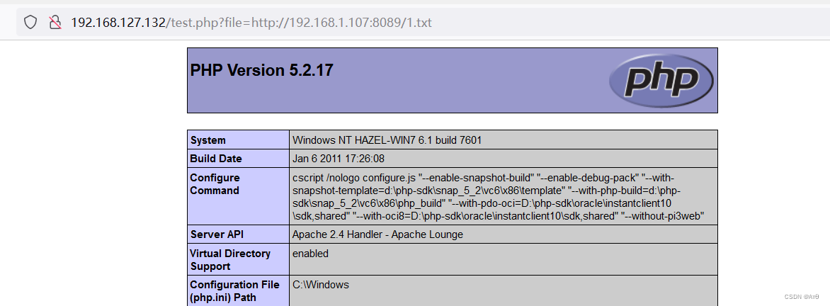
文件包含漏洞(二)
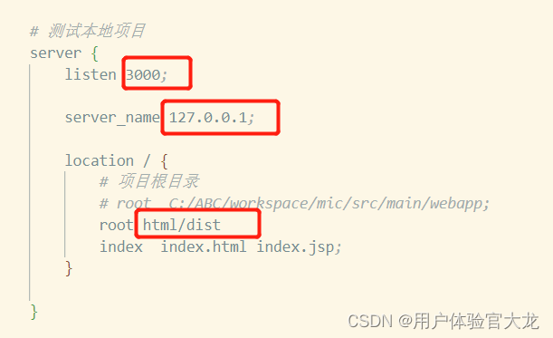
Can't the dist packaged by vite be opened directly in the browser
![[technical notes-08]](/img/52/0aff21b01ba7adbfcdb597d1aa85f9.png)
[technical notes-08]
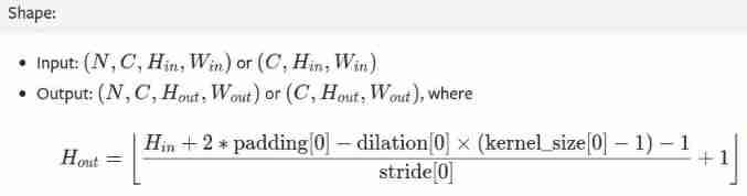
Pytorch Basics
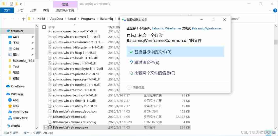
Balsamiq wireframes free installation
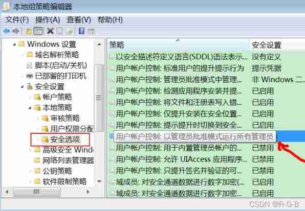
Win10 copy files, save files... All need administrator permission, solution
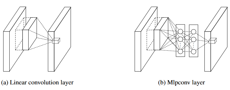
深度学习分类网络--Network in Network
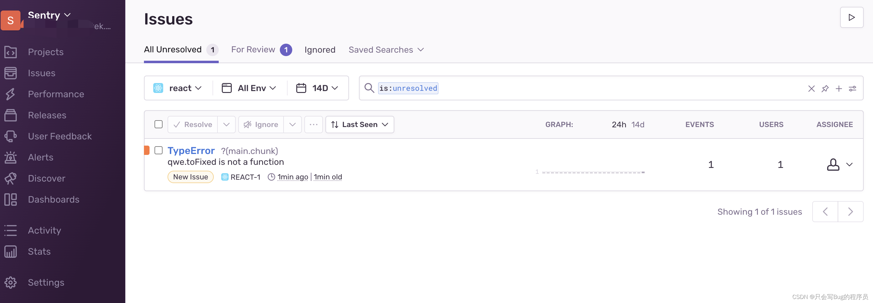
Record sentry's path of stepping on the pit

Visual studio import
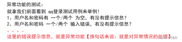
测试 - 用例篇
随机推荐
Gcnet: non - local Networks meet Squeeze excitation Networks and Beyond
Alibaba: open source and self-developed liquid cooling data center technology
Generics and generic constraints of typescript
all3dp. All Arduino projects in com website (2022.7.1)
Stick to the big screen UI, finereport development diary
来啦~ 使用 EasyExcel 导出时进行数据转换系列新篇章!
2022-2-14 learning xiangniuke project - Section 7 account setting
500. 键盘行
Web页面用户分步操作引导插件driver.js
Appnuim environment configuration and basic knowledge
线程池概述
all3dp.com网站中全部Arduino项目(2022.7.1)
Yyds dry inventory what is test driven development
在线音乐播放器app
1036 Boys vs Girls
PHP inner class name is the same as the inner class method name
Zzuli: maximum Convention and minimum common multiple
Software testing - concept
Balsamiq wireframes free installation
[paper translation] gcnet: non local networks meet squeeze exception networks and beyond