当前位置:网站首页>Operational amplifier application summary 1
Operational amplifier application summary 1
2022-07-07 03:57:00 【liht_ one thousand six hundred and thirty-four】
The content includes empty short and empty broken understanding , Reverse phase 、 In phase proportional operational amplifier circuit , Voltage follower , Correlation arithmetic circuit ( Add 、 reduce 、 ride 、 except 、 integral 、 differential 、 Logarithm and exponent ), Differential amplifier circuit ,I/V、V/I Conversion circuit , Voltage rise circuit ,F/V Conversion circuit , Active power filter , Phase shift circuit, etc . Purple text is a hyperlink , Click to automatically jump to relevant blog posts . Continuous updating , Originality is not easy. !
Catalog :
An overview of deficiency and discontinuity
One 、 Inverse proportional operation amplifier circuit
Two 、 In phase proportional operational amplifier circuit
3、 ... and 、 Voltage follower
Four 、 adder
5、 ... and 、 Subtracter
6、 ... and 、 Integral circuit
7、 ... and 、 Differential circuit
8、 ... and 、 Differential amplifier circuit
Nine 、I/V Conversion circuit
Ten 、V/I Conversion circuit
11、 ... and 、 Voltage rise circuit
Twelve 、F/V Conversion circuit
13、 ... and 、 Constant voltage source
fourteen 、 Logarithmic and exponential circuits
1、 Logarithmic circuit
2、 Exponential circuit
15、 ... and 、 Multiplication circuit
sixteen 、 Active power filter
1、 low pass filter
2、 High pass filter
seventeen 、 Monostable circuit
eighteen 、 Op amp as comparator ( Operational amplifier and comparator )
1、 The selection basis of the bias resistance of the comparator
2、 Maximum input voltage of comparator
nineteen 、 Dead zone circuit
twenty 、 Phase shift circuit
1、 Phase advance phase shift circuit
2、 Phase lag phase shift circuit
The 21st 、 Voltage source
1、 Standard voltage source based on comparator
2、 Voltage source based on op amp follower
appendix
1、 Integrated operational amplifier circuit Proteus Simulation
---------------------------------------------------------------------------------------------
An overview of deficiency and discontinuity
Because the voltage amplification of the operational amplifier is very large , The open-loop voltage amplification factor of general purpose operational amplifier is 80 dB above . The output voltage of the operational amplifier is limited , Generally in 10 V~14 V. Therefore, the differential mode input voltage of the operational amplifier is insufficient 1 mV, The two inputs are approximately equipotential , amount to “ A short circuit ”. The larger the open-loop voltage magnification , The closer the potentials of the two inputs are equal .“ Deficiency ” It refers to when the analysis operational amplifier is in the linear state , The two inputs can be regarded as equipotential , This characteristic is called false short circuit , Short for short . Obviously, the two inputs cannot be really short circuited .
Because the differential mode input resistance of the operational amplifier is very large , The input resistance of general-purpose operational amplifier is 1MΩ above . Therefore, the current flowing into the input of the operational amplifier is often insufficient 1uA, Far less than the current of the circuit outside the input . so Generally, the two inputs of the operational amplifier can be regarded as open circuit , And the greater the input resistance , The closer the two inputs are to the open circuit .“ Virtual break ” It refers to when analyzing that the op amp is in a linear state , The two inputs can be regarded as equivalent open circuit , This feature It's called a false open circuit , Short for virtual break . Obviously, you can't really open the two inputs .
In the process of analyzing the circuit , Don't worry about other features of op amp for the time being , It is analyzed according to the characteristics of virtual short and virtual break . Of course , If the op amp does not work in the amplification area , It does not meet the conditions of virtual short and virtual break , This method cannot be used to analyze . Such as comparator .
-------------------------------------------------------------------------------------------------
One 、 Inverse proportional operation amplifier circuit
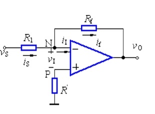
Voltage parallel negative feedback
shortcoming : The input resistance is less than R1;
advantage : Common mode voltage =(U+ + U-)/2=0, Low output resistance ;
characteristic : Falsely .
The signal voltage passes through the resistor R1 Add to the inverting input of the op amp , Output voltage Vo Through the feedback resistor Rf Feed back to the inverting input of the op amp , Constitute a voltage parallel negative feedback amplification circuit .
The in-phase terminal of the operational amplifier is grounded 0V, Inverting end and in-phase end “ Deficiency ”, So too. 0V, The input resistance of the inverting input terminal is very high “ Virtual break ”, There is almost no current injection and outflow , that R1 and Rf Equivalent to a series of , The current flowing through each component in a series circuit is the same , That is, flow through R1 The current and flow through Rf The current is the same .
Is= (Vs- V-)/R1
If= (V- - Vo)/Rf
V- = V+ = 0
Is= If
To solve the need to Vo==(-Rf/R1)*Vi

-------------------------------------------------------------------------------------------------
Two 、 In phase proportional operational amplifier circuit

Voltage parallel negative feedback
shortcoming : According to the deficiency ,U+=Vs,U-=Vs, Common mode voltage =(Vs+Vs)/2=Vs;
advantage : Input resistance =Vs/Ii, According to the virtual fault flow Rs Current Ii=0, High input resistance , Low output resistance .
According to the deficiency vN= vP=Vs, The input resistance of the inverting input terminal is very high “ Virtual break ”, There is almost no current injection and outflow , that R1 and Rf Equivalent to a series of , The current flowing through each component in a series circuit is the same , That is, flow through R1 The current and flow through Rf The current is the same .Vs/R1=(Vo-Vs)/Rf, have to vo=(1+Rf/R1)Vs
-------------------------------------------------------------------------------------------------
3、 ... and 、 Voltage follower


-------------------------------------------------------------------------------------------------
Four 、 adder

Due to the virtual short circuit , Net input voltage of op amp vI=0, The inverse end is virtual .
vI=0,vN=0.
Input current at the inverting end iI=0 The concept of , adopt R2 And R1 The sum of the currents is equal to passing through Rf The current of (Vs1 – V-)/R1 + (Vs2 – V-)/R2 = (V- –Vo)/Rf
If you take R1=R2=R3, from a,b The solution of the two formulas is -Vout=Vs1+Vs2
The minus sign in the formula is caused by inverse input , If another stage of inverse circuit is connected , The minus sign can be eliminated .


-------------------------------------------------------------------------------------------------
5、 ... and 、 Subtracter

Know from the falsehood , adopt R1 The current of is equal to passing through R2 Current , By the same token R4 The current of is equal to R3 Current , There are :
(V2 – V+)/R1 = V+/R2
(V1 – V-)/R4 = (V- - Vout)/R3
If R1=R2, be V+ = V2/2
If R3=R4, be V- = (Vout + V1)/2
From the empty short knowledge V+ = V-
therefore Vout=V2-V1 This is the subtracter .
----------------------------------------------------

-------------------------------------------------------------------------------------------------
6、 ... and 、 Integral circuit
Use the integral operation circuit to integrate different input signals , You can change the waveform .
For constant direct flow integral operation , It can improve the linearity of output voltage ;
Integrate the square wave , It can output triangular waves , The waveform is transformed ;
Integrate sine quantity , The output frequency can be the same , But amplitude 、 Cosine quantities with different initial phases .
The simulation example can be seen in Baidu online disk “ be based on Multisim10 Simulation of integral operation circuit of ”.

From the empty short knowledge , The voltage at the reverse input is equal to that at the same direction , Know from the falsehood , adopt R1 The current and current passing through C1 The current is equal to .
adopt R1 Current i=V1/R1
adopt C1 Current i=C*dUc/dt=-C*dVout/dt
therefore Vout=((-1/(R1*C1))∫V1dt The output voltage is proportional to the integral of the input voltage over time , This is the integral circuit .
if V1 Is a constant voltage U, Then the above formula is transformed into Vout = -U*t/(R1*C1) t Is time , be Vout The output voltage is a line from 0 To the straight line of negative power supply voltage varying with time .
A new solution to the principle of integral circuit -- Amplifier and capacitor “ Three changes ”.
Compare the same phase composed of resistance and arithmetic circuit 、 Inverse operational amplifier circuit , For the integral amplifier composed of capacitance and operational amplifier , How to understand and master in principle , Ordinary people often find it more difficult . The feedback resistor in the inverting amplifier , Replace with capacitors , It becomes an integral amplifier circuit as shown in Figure 1 . For resistance , It seems to be something more practical , The output state of the circuit can be seen at a glance , Replace with capacitors , Due to charging 、 Uncertainty of discharge , Capacitance is also a relatively “ virtual ” Object of , Its circuit output state , It's a little hard to figure out .

Figure 1
Composition of integrating circuit and signal waveform diagram Want to understand its output state , We must first understand the temperament of capacitance . The basic function of a capacitor is to charge 、 discharge , It's an energy storage element . Sensitive to changing voltage ( A strong reaction ), Insensitive to DC ( Even indifferent ), It has the characteristics of AC and DC isolation . For people who see that everything in the world is resistive , Capacitance can also be regarded as a variable resistance , Thus, the mystery of the output of the integrating circuit can be solved . According to the law of conservation of energy , Energy cannot be generated for no reason , Nor can it disappear for no reason , The theorem that the voltage at both ends of the capacitor cannot change suddenly is derived from it .
1) Charging moment , Charge has not yet accumulated between the two plates of the capacitor , Therefore, it can maintain the original state of zero voltage at both ends , But the instantaneous charging current is the maximum , It can be equivalent to a very small resistance or even a wire , If the capacitor is short circuited at the moment of charging , Not too bad , For example, in the main circuit of frequency converter , Limited current charging measures shall be taken for loop capacitance , It's just that ;
2) During capacitor charging , Over time , The charging voltage increases gradually , And the charging current gradually decreases , It can also be considered that the equivalent resistance of the capacitor changes from the minimum to the maximum ;
3) After the capacitor is fully charged , The voltage at both ends is the highest , But the charging current is basically zero , At this time, the capacitance is equivalent to the maximum resistance , For DC , It can even be equivalent to an open circuit , Infinite resistance .
4) Summarize the above , During capacitor charging , There is equivalent to the minimum resistance or conductor 、 Equivalent to the resistance from small to large 、 Equivalent to three states such as maximum resistance or open circuit . It is this changing characteristic of capacitance , The integral amplifier circuit can be transformed into three identities as shown in Figure 2 .
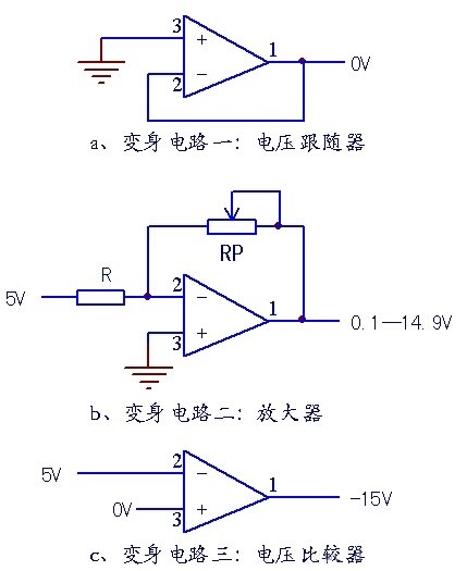
Figure 2
In the working process of integrating circuit “ Three changes ” See Figure 2 .
1) Voltage follower . In the input signal t0( Forward jump ) moment , The capacitor charging current is maximum , Minimum equivalent resistance ( Or as a conductor ), The circuit immediately turns into a voltage follower circuit , From the virtual ground characteristics of the circuit , The output is still 0V.
2) Inverting amplifier . In the input signal t0 After the moment, during the flat top , The capacitor is in a relatively gentle charging process , Its equivalent RP Experience less than R、 be equal to R And greater than R Three stages of , So in the amplification process , Under the action of amplification characteristics , In fact, it has experienced inverse attenuation 、 Reverse phase 、 Three small processes such as inverse amplification . Whether it's attenuation 、 Inverse or inverse amplification , At this stage , The integrating circuit actually acts as a linear amplifier .
3) In the second half of the input signal level term , The charging process of the capacitor is over , The charging current is zero , The capacitance is equivalent to an open circuit , The integral amplifier is amplified from closed-loop to open-loop comparison , The circuit then becomes a voltage comparator . At this time, the output value is the negative power supply value . It is said that people will change their faces , In fact, the circuit can also be transformed . Under the control of capacitance , The amplifier instantly changes three identities . Can see through these three identities of the integral amplifier , Integral amplifier “ Real body ” There is no hiding . amplifier , In fact “ Zoom in and compare , It's easier to zoom in ” Dancing and playing in the circle .
-------------------------------------------------------------------------------------------------
7、 ... and 、 Differential circuit

Know from the falsehood , Through capacitance C1 And resistance R2 The current is equal , From the empty short knowledge , The voltage at the same end and the opposite end of the operational amplifier is equal .
be : Vout = -i * R2 = -(R2*C1)dV1/dt, This is a differential circuit .
If V1 It's a sudden DC voltage , The output Vout Correspond to one direction and V1 Opposite pulse .
The OP AMP in the upper circuit can amplify the AC signal , At the same time, the network is a high pass filter , The phase lag of the signal 90°, The system may be unstable , So as to enter the situation of self-excited oscillation . The common differential circuit will be this type :

In the improved differential circuit , Input resistance and feedback capacitance are added , It is believed that this kind of circuit will often be seen in actual analog signal processing , It is precisely because of the introduction of these two elements , Make the signal produce 90° Phase shift of , such , It can keep the system stable .
But the circuit is not perfect , It is affected by the frequency of the input signal , When the frequency is too high , It will become an integral circuit .
An obvious feature of op amp is that it is easily affected by bias current , In order to minimize the influence of differential circuit , Usually we will add a resistor at the positive and negative input terminals , Limit the bias current , Typical circuits are as follows :

Sometimes a bias resistor is added to the forward input , The size is equal to the size of the feedback resistance .

-------------------------------------------------------------------------------------------------
8、 ... and 、 Differential amplifier circuit
All the amplification circuits mentioned above have an obvious feature , That is, they just amplify a certain potential point , The other potential point is grounded by default . And sometimes we There is no grounding at both ends of the potential that needs to amplify the voltage , Suitable for differential amplifier circuit .

chart 1 Basic circuit form (R1=R3,R2=R4)
Differential amplifier , According to the input 、 Different output methods , It can be divided into two terminal inputs 、 Double ended output ; Double ended input 、 Single ended output ; Single ended input 、 Double ended output , Single ended input 、 Single ended output and other circuit forms , Among them, for the differential amplifier composed of operational amplifier device circuit , Double ended input 、 The circuit form of single ended output is widely used .
The circuit advantages of differential amplifier : Amplify differential mode signal and suppress common mode signal , In terms of anti-interference performance “ Something extraordinary ”, This is inseparable from its circuit structure . You can use two triode circuits to build one, as shown in the figure 1 Medium a circuit , Explain the circuit characteristics of the differential amplifier .
(1) Amplifier circuit for single power supply , Its output ( namely Q1\Q2 Of C extremely ) Static working point is 1/2Vcc Most suitable , It can guarantee its maximum dynamic output range . as long as RC1、RB1 The value of equal offset element is appropriate , Can make UC1、UC2 The static voltage of is 2.5V, That is, static differential output voltage 2.5V-2.5V=0V;
(2) The circuit design should make Q1、Q2 The static working parameters of are consistent , The two constitute “ Mirror image ” circuit ,RE Is the current negative feedback resistance , Its DC resistance is small , The dynamic resistance is extremely ( The current flowing is almost constant ), To improve the differential performance of the circuit .
(3) When IN+=IN- when , Or when the signal voltage of both rises and falls synchronously ,OUT+、OUT- The terminal voltage is also rising and falling synchronously , And rise 、 The decrease is equal , Its input differential output value will still be 0V. For example, two input signals are generated on a static basis Q1、Q2 The same increment of base current , Then the collector voltage will drop , Such as by 2.5V Reduced to 1.5V when , be UC1-UC2=1.5V-1.5V=0V, This shows that the circuit ignores the common mode input signal , It has excellent anti-interference performance .
as everyone knows ,RS485 Communication circuit , Is to use differential bus transmission , It has a strong anti-interference effect .
(4) When IN+、IN- The input signal has relative changes on a static basis , namely IN+-IN-≠0 when , Such as IN+ When the input voltage changes in the positive direction ,OUT- Will change in the negative direction ( meanwhile OUT+ Will change in a positive direction ), Make the two outputs deviate in reverse 2.5V Produces a signal output . When OUT- by 1.5V,OUT+ by 3.5V when , At this time, it produces 2V Signal voltage output .
It shows that the circuit effectively amplifies the differential mode signal . Differential amplifier is a selective amplifier , Ignore common mode interference , Amplify the useful differential mode signal .
chart 1 Medium b circuit , It is a differential amplifier composed of operational amplifier devices . The picture clearly shows , Whether the input signal is 2.5V or 5V, as long as IN1=IN2,OUT The end is 0V. From this point of view and significance , When the bias element of the differential amplifier R1=R3,R2=R4 when , also IN1=IN2 when , Its output “ Falsely ”.
Double ended input 、 Why does the output end of the single ended output differential amplifier appear “ Falsely ” Characteristics ?


From the empty short knowledge Vx = V1 ---->a
Vy = V2 ---->b
Know from the falsehood , No current flows through the input of the operational amplifier , be R1、R2、R3 It can be regarded as series connection , The current through each resistor is the same , electric current I=(Vx-Vy)/R2 ---->c
be :Vo1-Vo2=I*(R1+R2+R3) = (Vx-Vy)(R1+R2+R3)/R2 ---->d
Know from the falsehood , Flow through R6 And flow through R7 The current is equal to , if R6=R7, be Vw = Vo2/2 ---->e
In the same way R4=R5, be Vout – Vu = Vu – Vo1, so Vu = (Vout+Vo1)/2 ---->f
From the empty short knowledge ,Vu = Vw ---->g
from efg have to Vout = Vo2 – Vo1 ---->h
from dh have to Vout = (Vy –Vx)(R1+R2+R3)/R2 In the above formula (R1+R2+R3)/R2 Is the fixed value , This value determines the difference (Vy –Vx) The magnification of . This circuit is the differential amplification circuit .

When using differential amplification circuit , One thing needs special attention , Not only |k*(U1-U2)|<15( Preferably less than 13V about , Get better results ), and Un And Up It should also be less than 15v, Otherwise, the amplification will not work in the linear region , Cause the circuit to work abnormally .
-------------------------------------------------------------------------------------------------
Nine 、I/V Conversion circuit

It is also a current amplifier .
Many controllers accept signals from various detection instruments 0~20mA or 4~20mA electric current , The circuit converts the current into voltage and then sends it to ADC Convert to a digital signal . Pictured 4~20mA Current flows through the sample 100Ω resistance R1, stay R1 There will be 0.4~2V Voltage difference of .
Know from the falsehood , No current flows through the input of the operational amplifier , Then flow R3 and R5 The current is equal to , Flow through R2 and R4 The current is equal to .
so :(V2-Vy)/R3 = Vy/R5 ----a
(V1-Vx)/R2 = (Vx-Vout)/R4 ----b
From the empty short knowledge : Vx = Vy ----c
The current flows from 0~20mA change , be V1 = V2 + (0.4~2) ----d
from cd Type in b Formula (V2 + (0.4~2)-Vy)/R2 = (Vy-Vout)/R4 ----e
If R3=R2,R4=R5, By e-a have to Vout = -(0.4~2)R4/R2 ----f
In the figure R4/R2=22k/10k=2.2, be f type Vout = -(0.88~4.4)V, That is , take 4~20mA The current is converted into -0.88 ~ -4.4V voltage , This voltage can send ADC To deal with . notes : If the current in the figure is reversed Vout = +(0.88~4.4)V.
-------------------------------------------------------------------------------------------------
Ten 、V/I Conversion circuit

Current can be converted into voltage , Voltage can also be converted into current , The anti-interference ability of current transmission is better . The above figure shows such a circuit . The negative feedback of this figure is not directly fed back through resistance , Instead, a triode is connected in series Q1 Emission junction , Don't think it's just a comparator . As long as it's an amplifier circuit , The law of virtual short and virtual break still conforms to .
Know from the falsehood , No current flows through the input of the operational amplifier , be (Vi – V1)/R2 = (V1 – V4)/R6 ----a
Empathy (V3 – V2)/R5 = V2/R4 ----b
From the empty short knowledge V1 = V2 ----c
If R2=R6,R4=R5, By abc Formula V3-V4=Vi
The above formula explains R7 Voltage at both ends and input voltage Vi equal , Through R7 Current I=Vi/R7, If the load RL<<100KΩ, Through Rl And through the R7 The current is basically the same .
-------------------------------------------------------------------------------------------------
11、 ... and 、 Voltage rise circuit
Just be an ordinary follower , Add the signal to Vcc/2 It's OK on the Internet OK, Consider expansion AD The accuracy can be slightly enlarged .

V+=2.5V,LM358P The operational amplifier is short ,V-=2.5V,Uo-2.5=2.5-Ui,Uo=5-Ui.

If the signal frequency is low, you need to increase the capacitance , The capacitance value is initially calculated by the turning frequency 1/(2*3.14*R*C).
-------------------------------------------------------------------------------------------------
Twelve 、F/V Conversion circuit

The measured frequency signal is transported into A, NAND gate B、C、D Zoom in , Clipping , Shaping into a regular waveform with the same frequency as the measured signal , As the input signal of monostable trigger circuit .
-------------------------------------------------------------------------------------------------
13、 ... and 、 Constant voltage source

VD1 The pressure drop of the pipe after conduction Uz Basically unchanged , Input like this A1 The voltage at the inverting input is Uz, This is a stable DC voltage . According to the closed-loop gain formula of integrated operational amplifier ( According to the previous empty short empty break ) The output voltage can be calculated Uo:Uo=R3/R2*Uz.
because Uz Stable , resistance R2 and R3 Stable , So output Uo Stable , explain A1 With constant voltage output characteristics .

-------------------------------------------------------------------------------------------------
fourteen 、 Logarithmic and exponential circuits
1、 Logarithmic circuit


Logarithmic operation Ui Not less than 0, Otherwise, the triode BE Knot reverse bias cut-off , There is no feedback loop .
----------------------------------------------------
2、 Exponential circuit

Exponential operation Ui Not less than 0, Otherwise, the triode BE Knot reverse bias cut-off , There is no feedback loop .
-------------------------------------------------------------------------------------------------
15、 ... and 、 Multiplication circuit


Division composed of analog multiplier 、 Calculation of square root and RMS detection circuit :
1) Division operations

Here Ui2 Must be greater than 0
----------------------------
2) Square root operation

Here Ui1 Must be less than 0

Here Ui1 No matter positive or negative
----------------------------
3) RMS detection circuit

-------------------------------------------------------------------------------------------------
sixteen 、 Active power filter
1、 low pass filter
1) First order low pass filter

Of the last formula (1+Rf/R1) It can magnify , Strong load carrying capacity .
----------------------------
2) Second order low pass filter

----------------------------------------------------
2、 High pass filter
The position of the resistance and capacitance in the above figure are reversed .
-------------------------------------------------------------------------------------------------
seventeen 、 Monostable circuit

Static , capacitance C1 After charging , Operational release A1 Forward terminal voltage U2=V+,A1 Output high level . When the input voltage Ui Turn to low power , diode D1 Conduction , capacitance C1 adopt D1 Rapid discharge , send U2 Suddenly fell to 0V, Cause at this time U1>U2, So op amp A1 Output low level . When the input voltage becomes high , diode D1 end ,V+ the R3 Give the capacitor C1 Charge , When C1 The voltage on the is greater than U1 when ,A1 The output goes high again , Thus ending a monostable trigger .
If the diode D1 Get rid of , This circuit has power on delay function .
-------------------------------------------------------------------------------------------------
eighteen 、 Op amp as comparator ( Operational amplifier and comparator )
1、 The selection basis of the bias resistance of the comparator
25 Micro safety is generally no problem , According to the parameter of maximum bias current , When the comparator reverses, the bias current will have 0.25 Changes within microamps , The greater the partial voltage bias current is, the less susceptible it is to interference , Of a comparator “ precision ” The higher , The specific bias current depends on the accuracy requirements .
For example, you need a comparator in 10V reverse , use 2.5 The comparator may be in if the current is biased by microampere 9~11v reverse , use 25 Wei'an will be 9.9~10.1v Time reversal , use 0.25 Milliampere will be 9.99~10.01v Time reversal , And so on , The above is just a rough estimate for illustrative purposes , The specific size must be determined by oneself .
(V+) - (V-) >= X, X When is the output high level ;(V+) - (V-) <= Y, Y When is the output low level .
The offset voltage is 10mV, Then the reference voltage 2.5V, The comparator will be in 2.49V~2.51V Response between ;
The offset voltage is 1mV, Then the reference voltage 2.5V, The comparator will be in 2.499V~2.501V Response between .
Examples of specific components :
1)LM324 Input offset voltage maximum 5mV
2)OP07 With very low input offset voltage ( about OP07A The maximum is 25μV), At very low input signal input forward end or reverse end ( such as 20mV) Try to make a comparison .
----------------------------------------------------
2、 Maximum input voltage of comparator

-------------------------------------------------------------------------------------------------
nineteen 、 Dead zone circuit
When the input signal Vin Enter a certain range ( dead zone ) when , The output voltage is 0; When out of this range , The output voltage of the circuit changes with the input signal .
The figure shows the diode bridge dead band circuit .

-------------------------------------------------------------------------------------------------
twenty 、 Phase shift circuit
1、 Phase advance phase shift circuit
In electronic circuits, it is often necessary to change the phase of sine wave signals , Such as phase shifting . Using OP AMP and RC The network can build a phase-shifting range 0~180 Degree phase shift circuit . Phase lead ( The output is ahead of the input ) The phase shift circuit of is shown in the figure :

----------------------------------------------------
2、 Phase lag phase shift circuit
Through adjustment R3, You can change the size of the phase shift , And basically will not affect the amplitude of the output voltage . And phase lag ( Output lags input ) The phase shift circuit of is :

-------------------------------------------------------------------------------------------------
The 21st 、 Voltage source
1、 Standard voltage source based on comparator

Q19 It is the reference voltage source APL431, Used to generate 2.5V Reference voltage of .
Generated by the reference voltage source +2.5V The reference voltage passes R61、R50 partial pressure , stay R50 The pressure drop on is equal to 1.05V, So the voltage comparator U2B Positive phase input of 5 The foot voltage is constant 1.05V.
At power on , Voltage comparator U2B Inverting input of 6 Feet due to R51 At low level , here 5 The foot potential is higher than the inverting input 6 Foot potential , Voltage comparator U2B The output of the 7 Pin output high level , Drive FET Q34 Conduction .Q34 After conduction ,+3.3V The voltage passes through Q34 Of D、S extremely 、 resistance R52、R51 Divide the voltage and add it to the voltage comparator U2B Inverting input of 6 foot , Due to the voltage comparator U2B Positive phase input of 5 The foot voltage is constant 1.05V, therefore , When the voltage comparator U2B Inverting input of 6 The pin voltage is higher than 1.05V when , Output terminal 7 The pin will output low level , Make conductive Q34 end .
stay Q34 At the deadline ,U2B Of 6 The pin voltage will drop below 1.05V, At this time, the output terminal will output high level again ,Q34 Conduction . So again and again , You can make the voltage output terminal Q34 Of S The pole voltage is stable at the set value . Output voltage Vout=1.05x(1+R52/R51)≈2.6V, by DDR Memory powered .
----------------------------------------------------
2、 Voltage source based on op amp follower

Make Rf=0,R1=∞, The in-phase proportional op amp above becomes a voltage follower , It has extremely high input impedance , Extremely low output impedance .
For example, the current connection 1 A load , But its load current changes greatly , Up to 200mA. Here's the picture Vout Power the load ,51R Prevent the triode at the moment of power on CE Spikes caused by capacitance .

-------------------------------------------------------------------------------------------------
appendix
1、 Integrated operational amplifier circuit Proteus Simulation
2、 Summary of Operational Amplifier Applications 2
-------------------------------------------------------------------------------------------------
边栏推荐
- codeforces每日5题(均1700)-第七天
- 哈夫曼树基本概念
- Preprocessing - interpolation
- Enter the rough outline of the URL question (continuously updated)
- OSCP工具之一: dirsearch用法大全
- .net中 接口可以有默认实现了
- Baidu map JS development, open a blank, bmapgl is not defined, err_ FILE_ NOT_ FOUND
- QT 项目 表格新建列名称设置 需求练习(找数组消失的数字、最大值)
- Probability formula
- 二叉搜索树的实现
猜你喜欢
Arduino droplet detection

如何检测mysql代码运行是否出现死锁+binlog查看
List interview common questions

2022年上半年HIT行业TOP50

Antd Comment 递归循环评论

Restcloud ETL Community Edition June featured Q & A
海思3559万能平台搭建:RTSP实时播放的支持

Kotlin Android 环境搭建

On file uploading of network security

R data analysis: how to predict Cox model and reproduce high score articles
随机推荐
海思万能平台搭建:颜色空间转换YUV2RGB
The true face of function pointer in single chip microcomputer and the operation of callback function
How to customize the shortcut key for latex to stop running
Probability formula
[development software] tilipa Developer Software
Implementation steps of docker deploying mysql8
Top 50 hit industry in the first half of 2022
Kotlin Android environment construction
First understand the principle of network
Clock in during winter vacation
QT opens a file and uses QFileDialog to obtain the file name, content, etc
SSL certificate deployment
维护万星开源向量数据库是什么体验
25. (ArcGIS API for JS) ArcGIS API for JS line modification line editing (sketchviewmodel)
机器学习笔记 - 使用机器学习进行鸟类物种分类
一些常用软件相关
VHDL implementation of arbitrary size matrix multiplication
Code quality management
大白话高并发(二)
Kotlin Android 环境搭建