当前位置:网站首页>GPIO port details, Hal library operation keys
GPIO port details, Hal library operation keys
2022-07-03 09:41:00 【two thousand and twenty-one point zero nine】
This blog knowledge comes from Mr. Wei Dongshan's 7 Internet of things course .
One 、GPIO Detailed explanation
1、STM32F103C8T6 Altogether 48 One pin .
2、 Press A、B、C grouping , Each group 16 One pin , The number is 0~15,STM32F103C8T6 Yes 2 Group GPIO, Each group has 16 One pin , namely 32 individual GPIO Pin .
3、GPIO Working mode
STM32F103 Series of I/O The pins share 8 Working mode , There are four output modes : Push pull output 、 Open drain output 、 Multiplexing push pull output 、 Reuse open drain output ; There are four input modes : Pull up input 、 Drop down input 、 Floating input 、 Analog input .
- Push pull output ( Push-Pull, PP)

The push-pull structure consists of two MOS The tubes are connected in a complementary and symmetrical manner , At any time, one of the triodes is always on , The other triode is off . Pictured above 1 Shown , The interior consists of a P-MOS Tube and a N-MOS Tube composition , Two MOS The grid of the tube ( Gate, G) To the left “ Output control ” , Drain electrode ( Drain, D) Connected to external output , P-MOS The source of the tube ( Source, S) Receive VDD( 3.3V),N-MOS The source of the tube is connected to Vss( 0V).
MOS The tube is used as a switch ,“ Output control ” To two MOS Apply a certain voltage to the tube grid , P-MOS Conduction between the source and drain of the tube ,VDD after P-MOS Tubular S->G->D Output , N-MOS The tube is in a high resistance state ( The resistance is very high , Approximate open circuit ), The overall external is high level ;“ Output control ” Cancel to two MOS Apply voltage to the tube grid , P-MOS Tube source and grid cut-off , P-MOS The tube is in a high resistance state , N-MOS The source and drain of the tube are connected , The overall external is low level .
MOS The tube is used as a switch ,“ Output control ” To two MOS Apply a certain voltage to the tube grid , P-MOS Conduction between the source and drain of the tube ,VDD after P-MOS Tubular S->G->D Output , N-MOS The tube is in a high resistance state ( The resistance is very high , Approximate open circuit ), The overall external is high level ;“ Output control ” Cancel to two MOS Apply voltage to the tube grid , P-MOS Tube source and grid cut-off , P-MOS The tube is in a high resistance state , N-MOS The source and drain of the tube are connected , The overall external is low level .
- Open drain output ( Open-Drain, OD)
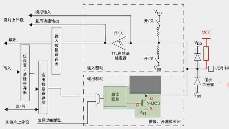
In open drain mode ,“ Output control ” Will not control P-MOS tube , “ Output control ” Only to N-MOS Apply a certain voltage to the tube grid , Two MOS All tubes are in the cut-off state , The two drains are suspended , It's called open drain .“ Output control ” Cancel the applied voltage of the grid , PMOS The tube is still in the high resistance state , N-MOS The pipe is open , The overall external is low level .
The open drain output mode can be equivalent to P-MOS The tube is regarded as nonexistent . That is, only low level can be output in this mode , To output high level , External resistance is required , The connected resistance is called pull-up resistance , At this time, the output level depends on the external power supply voltage of the pull-up resistor , As shown in the figure above, red VCC+ External circuit of resistance .
Push pull output mode can directly output high level , Open drain output mode requires external pull-up resistor to output high level , But the open drain output has some characteristics that the push-pull output does not have :
① Using external circuit driving capability . As shown in the figure above ,“ Output control ” Only a small gate drive current is required , VCC Increase the driving current for the external load through the pull-up resistor ;
② Realize level conversion . The push-pull output mode consists of VDD Provide , That is, only 3.3V level . After using the open drain output mode , VCC It can be for 5V, Thus, the effect of level conversion is realized .
③ Easy to implement “ Logic and ” function . Multiple open drain pins can be used directly together , Connect a suitable pull-up resistor uniformly , Can be realized “ Logic and ” Relationship , That is, when all pins output high level , The output is high level , If any pin outputs low level , Then output low level . stay I2C、 SMBUS And other bus circuits are often used .
VCC Can connect 5V/3.3V, Improve the driving ability of pins , I think the internal structure of the chip is very thin , The current that can pass through is limited , Add a thick circuit outside to connect , It can drive a large current . If VCC yes 5V It can realize the function of level conversion , Because normally ,IO The output is 3.3V.
- Reuse function push-pull / Open drain output ( Alternate Function, AF)
GPIO In addition to being a general-purpose input / The output pin uses an external pin , It can also be used as an on-chip peripheral ( USART、 I2C、 SPI etc. ) Dedicated pin , That is, one pin can be used for many purposes , But one pin can only use one of the multiplexing functions at the same time .
When the pin is set to the multiplexing function , The multiplexed push-pull output mode or multiplexed open drain output mode can be selected , When set to multiplex open drain output mode , It needs to be connected with pull resistance .
- Pull up input mode ( Input Pull-up)
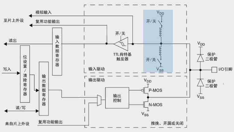
As shown in the figure above , VDD Through the switch 、 Pull up resistance , Connect external I/O Pin . When the switch is closed , external I/O When there is no input signal , The default input is high . The typical application of this mode is the external key , When no key is pressed , MCU The pin of is the determined high level , When the key is pressed , The pin level is pulled to low level .
- Drop down input mode ( Input Pull-down)
As shown in the figure above , Vss Through the switch 、 Pull down resistance , Connect external I/O Pin . When the switch is closed , external I/O When there is no input signal , The default input is low . The typical application of this mode is also the external key , When no key is pressed , MCU The pin of is the determined low level , When the key is pressed , The pin level is pulled high .
- Floating input mode ( Floating Input)
As shown in the figure above , Two up / The pull-down resistance switches are disconnected , Neither pull-up nor pull-down , I/O The pins are connected directly TTL Schottky barrier
trigger , here I/O The pin is floating , The reading level is uncertain , What level is the external signal , MCU The pin inputs what level . MCU Reset after power on , The default is floating input mode .
- Analog input mode ( Analog mode)
As shown in the figure above , Two up / The pull-down resistance switches are disconnected , meanwhile TTL The Schottky trigger switch is also off , The pin signal is directly connected to the analog input , Realize the acquisition of external signals .
Two 、cubeMX Set up GPIO
1、 Choose one first GPIO, The choice here is PA1 For export .
2、 Click on the left GPIO.
3、 Click... In the middle PA1 Options , Then you can set PA1 Detailed parameters of .
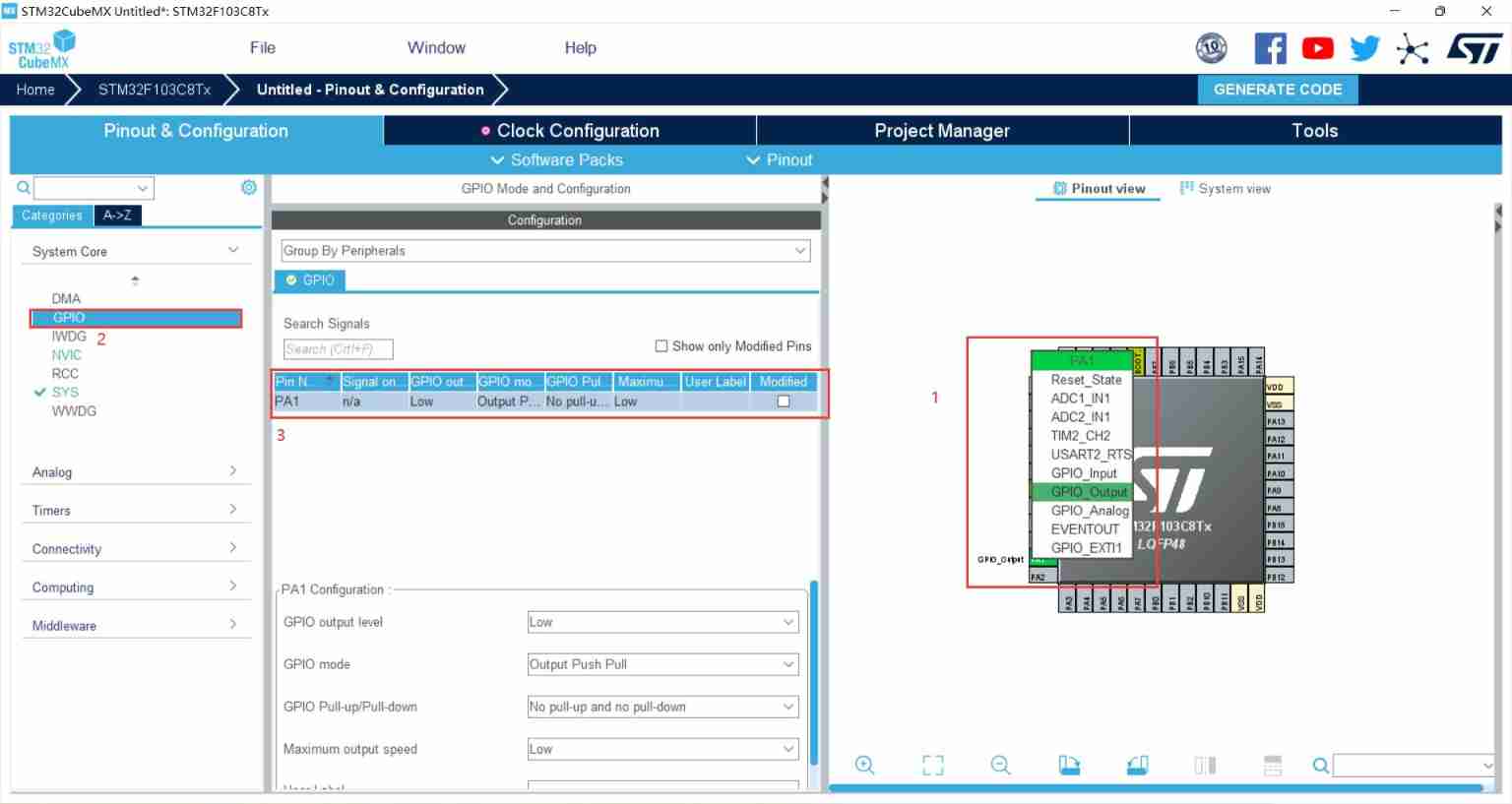
4、 Here you can set the default output level 、 The output mode 、 Whether to pull up or down 、 The frequency of the clock is high, medium and low .
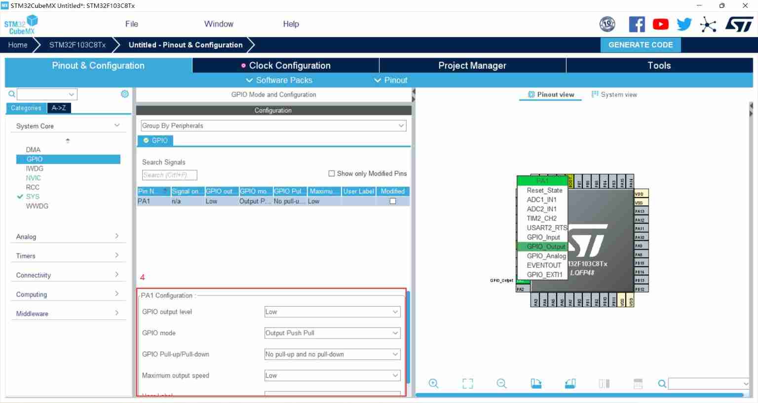
5、 It can be for PA1 Set an alias , Here we take LED. In the code, it is shown as : stay mian() find MX_GPIO_Init(), And then right-click go to definition, You can find it .


3、 ... and 、cubeMX Operate the buttons
1、 Hardware analysis of keys

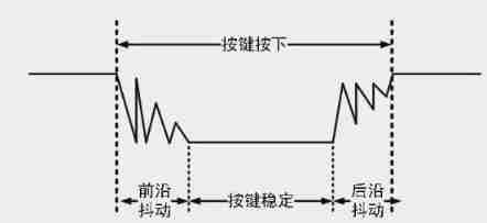
The mechanical key will shake during pressing , So there will be hardware anti jitter and software anti jitter , The hardware anti jitter is the capacitance in the figure above .
2、cubeMX Generate engineering framework
PA0 Select input mode , Because for hardware pull , So you don't have to choose up and down . When the default key is released ,IO Read as high level , When the key is pressed ,IO Read low .
PA1 Set as output , control LED The lamp .

3、keil Some control logic
stay main() Functional while In circulation , Write control logic , Time delay is set 8ms Software De chattering . Press the key to press LED Extinguish , Release to LED bright .
  while (1)
  {
    /* USER CODE END WHILE */

    /* USER CODE BEGIN 3 */
    if(HAL_GPIO_ReadPin(GPIOA,GPIO_PIN_0) == GPIO_PIN_RESET)
    {
        HAL_Delay(8);
        if(HAL_GPIO_ReadPin(GPIOA,GPIO_PIN_0) == GPIO_PIN_RESET)
        {
            HAL_GPIO_WritePin(GPIOA,GPIO_PIN_1,GPIO_PIN_SET);
        }
        else
        {
            HAL_GPIO_WritePin(GPIOA,GPIO_PIN_1,GPIO_PIN_RESET);
        }
    }
    }
  /* USER CODE END 3 */
}边栏推荐
- Send mail using WP mail SMTP plug-in
- CATIA automation object architecture - detailed explanation of application objects (III) systemservice
- 顺利毕业[3]-博客系统 更新中。。。
- Leetcode daily question (1856. maximum subarray min product)
- Leetcode daily question (516. long palindromic subsequence)
- LeetCode每日一题(2232. Minimize Result by Adding Parentheses to Expression)
- Make the most basic root file system of Jetson nano and mount NFS file system on the server
- LeetCode每日一题(2212. Maximum Points in an Archery Competition)
- UCI and data multiplexing are transmitted on Pusch (Part 4) --small block lengths
- MySQL Data Definition Language DDL common commands
猜你喜欢

【男保姆式】教你打开第一个微信小程序
Spark cluster installation and deployment
![[CSDN]C1训练题解析_第四部分_Web进阶](/img/ee/2e9756cc0e2e6eda83e1b2304c0bd6.png)
[CSDN]C1训练题解析_第四部分_Web进阶

Hudi data management and storage overview
Convert IP address to int

MySQL data manipulation language DML common commands
Nodemcu-esp8266 development (vscode+platformio+arduino framework): Part 2 --blinker_ Hello_ WiFi (lighting technology - Mobile App control routine)
![【顺利毕业】[1]-游览 [学生管理信息系统]](/img/91/72cdea3eb3f61315595330d2c9016d.png)
【顺利毕业】[1]-游览 [学生管理信息系统]

【22毕业季】我是毕业生yo~

Difference of EOF
随机推荐
Jestson Nano 从tftp服务器下载更新kernel和dtb
Directory and switching operation in file system
[22 graduation season] I'm a graduate yo~
Runtime.getRuntime().gc() 和 Runtime.getRuntime().runFinalization() 的区别
CEF下载,编译工程
What do software test engineers do? Pass the technology to test whether there are loopholes in the software program
[CSDN]C1訓練題解析_第三部分_JS基礎
Leetcode daily question (1162. as far from land as possible)
Win10 install elk
QT sub window is blocked, and the main window cannot be clicked after the sub window pops up
Make the most basic root file system of Jetson nano and mount NFS file system on the server
Leetcode daily question (2232. minimize result by addressing parents to expression)
LeetCode每日一题(745. Prefix and Suffix Search)
解决Editor.md上传图片获取不到图片地址问题
用Redis实现分布式锁
UCI and data multiplexing are transmitted on Pusch - Part I
numpy. Reshape() and resize() functions
Development of electrical fire system
Learning C language from scratch -- installation and configuration of 01 MinGW
DSP data calculation error