当前位置:网站首页>Application of I2C protocol of STM32F103 (read and write EEPROM)
Application of I2C protocol of STM32F103 (read and write EEPROM)
2022-07-03 03:54:00 【And stuffed】
Summary
This article mainly records that individuals are learning I2C Some personal opinions of the agreement , And based on I2C Protocol implementation STM32 Reading and writing EEPROM The data of
Statement : Because of limited personal ability , This article is only personal learning notes , If there are any mistakes, please point out
I2C features
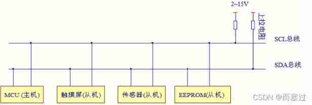
- Support device bus , That is, multiple devices can share signal lines . In a I2C Multiple can be connected in the communication bus I2C Communication equipment , Support multiple communication hosts and multiple pass through slaves
- Use two bus lines , A two-way serial data line (SDA), A serial clock line (SCL).SCL Used for synchronization of data sending and receiving
- Each device connected to the bus has a separate address , Access different devices through this address
- The bus is connected to the power supply through pull-up resistor , When I2C When the device is idle , It will output a high resistance state , When all devices are idle , Both output high resistance state , Pull the bus to high level by pull-up resistor
- When multiple hosts use the bus , Will use arbitration to decide which device occupies the bus
I2C The basic process of reading and writing
The host writes data to the slave 
The host reads data from the slave

- When the master communicates with the slave ,S Indicates from the host I2C The transmission start signal generated by the interface , At this time, all are connected to I2C All slaves on the bus will receive this signal .
- In order to operate the slave correctly , Therefore, the slave address broadcast by the host (SLAVE ADDRESS), stay I2C On the bus , The address of each device is unique , Therefore, the slave is selected .( The slave address can be 7 Bit or 10 position )
- After successfully finding the slave , The selection bit of the direction to be transmitted , This bit is 0 when , Indicates that the host writes data to the slave , This bit is 1 when , Indicates that the host reads data from the slave (0 Write 1 read )
- After receiving the matching address from the slave , The host or from the opportunity returns a reply (ACK) Or no response (NACK) The signal , Only after receiving the reply signal can you continue to send or receive data .
Writing data
The configuration direction transmission bit is “ Writing data ” Direction (0), After the broadcast, the address , After receiving the reply signal , The master officially begins to write data to the slave (DATA), Packet size is 8 position , The host sends one byte of data each time , We have to wait for the response signal from the slave (ACK), Repeat the process , It can be transmitted to the slave N Data , Finally, when the transmission ends , The master sends a stop signal to the slave , It means no more data transmission .
Reading data
The configuration direction transmission bit is “ Reading data ” Direction (1), After the broadcast, the address , After receiving the reply signal , The master officially begins to write data to the slave (DATA), Packet size is 8 position , The host sends one byte of data each time , We have to wait for the response signal from the slave (ACK), Repeat the process , It can be transmitted to the slave N Data . When the host wants to stop receiving data , The slave can return a non reply signal (NACK), The slave automatically stops data transmission
Read and write data
Besides basic reading and writing ,I2C Communication is more commonly used in composite mode , The transmission process has two start signals (S). Usually in the first transmission , The host by SLAVE_ADDRESS After finding the slave device , Send a piece of data , This data represents the internal memory or memory address of the slave device ( Pay attention to distinguish it from SLAVE_ADDRESS The difference between ); In the second transmission, it is the reading and writing of the address change .
In short, the first transmission read-write address , The second is to read and write specific data
I2C The starting state of

- Start
SCL High level ,SDA From high level to low level
/* SCL High level , A jump edge appears  */
void I2C_Start(void){

	SDA_HIGH();
	SCL_HIGH();
	delay();
	SDA_LOW();
	delay();
	SCL_LOW():
	delay();
}
- end
SCL Is a high level ,SDA From low level to high level
/* SCL High level , An up jump edge appears  */
void I2C_Stop(void){

	SDA_LOW();
	SCL_HIGH();
	delay();
	SDA_HIGH();
}
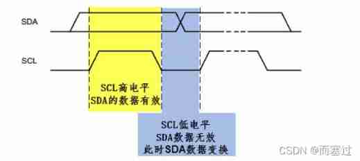
3. The validity of the data
SDA The data line is in SCL One bit of data per clock cycle (8 Bytes ),SCL When it's high level SDA The data represented is valid , here SDA Indicates data for high level “1”, Low level indicates data “0”; When SCL Low power level ,SDA Invalid data , Usually at this time SDA Carry out level switching , Prepare for the next data .
To transmit data
- Byte format
Send to SDA Each byte on the line must be 8 position , The number of bytes that can be sent per transmission is unlimited , But each byte must be followed by a response bit
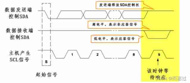
- Respond to
Data transmission must be responsive , The corresponding response clock is generated by the host . Responses include “ The reply ”(ACK) and " Non response " The signal (NACK). On the ninth clock , Transmitter release SDA Line ( high )SDA A high level indicates a non reply signal ,SDA A low level indicates a reply signal ,SCL Line for high-low level conversion , A clock signal will be generated .
EEORPM
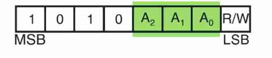
This experiment adopts EEPROM chip (AT24C02), take A0/A1/A2 All grounded , Therefore, the address of the device 7 The bit address is 0x50(1010000), Read the address :0xA1(10100001), Write the address :0xA0(10100000);I2C It is realized by software simulation .
Programming flow
- Configure peripheral pins
- Write simulation I2C Timing control function
- Write basic I2C Read and write functions
- Write, read and write EEPROM The functions here
- Write test functions
Code implementation
Software simulation I2C
void I2C_Delay(void){

	uint8_t i;
	for(i=10;i>0;i--);
}
/* I2C Start signal  */
void EEPROM_I2C_Start(void){

	//SCL High level ,SDA There is a falling edge
	SDA_HIGH();
	SCL_HIGH();
	I2C_Delay();
	SDA_LOW();
	I2C_Delay();
	SCL_LOW();
	I2C_Delay();
}
/* I2C End signal  */
void EEPROM_I2C_Stop(void){

	//SCL High level ,SDA A rising edge appears
	SDA_LOW();
	SCL_HIGH();
	I2C_Delay();
	SDA_HIGH();
	I2C_Delay();
}
/* I2C Answer signal  */
void EEPROM_I2C_ACK(void){

	SDA_LOW();		// Answer signal
	I2C_Delay();
	SCL_HIGH();//CPU Generate a clock
	I2C_Delay();
	SCL_LOW();//CPU Generate a clock
	I2C_Delay();
	SDA_HIGH();			//CPU Release SDA Line

}
/* I2C No response signal  */
void EEPROM_I2C_NACK(void){

	SDA_HIGH();		// No response signal
	I2C_Delay();
	SCL_HIGH();//CPU Generate a clock
	I2C_Delay();
	SCL_LOW();//CPU Generate a clock
	I2C_Delay();
}

/* I2C Waiting for an answer  */
uint8_t EEPROM_I2C_WaitAck(void){

	// return 0 The answer is correct , return 1 Indicates no device response
	uint8_t re;

	SDA_HIGH();		//CPU Release SDA Bus
	I2C_Delay();
	SCL_HIGH();//CPU Generate a clock
	I2C_Delay();

	//CPU Now read SDA Oral state (SDA Low level return reply , High level return non reply )
	if(EEPROM_I2C_SDA_Read())
		re = 1;
	else
		re = 0;
	SCL_LOW();
	I2C_Delay();
	return re;
}

/* CPU towards I2C The bus sends 8bit data  */
void I2C_SendByte(uint8_t Byte){


	uint8_t i;

	// Send the high bit of the byte first bit7
	for(i = 0; i < 8 ;i++){

		if(Byte & 0x80)	// Judge the highest logical value
			SDA_HIGH();
		else
			SDA_LOW();
		I2C_Delay();

		SCL_HIGH();//CPU Generate a clock
		I2C_Delay();
		SCL_LOW();
		if( i == 7)
			SDA_HIGH();	// The last data transmission is completed , Release the bus

		Byte <<= 1; 	// One left bit, It is convenient to send the next bit of data in the next cycle
		I2C_Delay();

	}
}
/* CPU from I2C Bus read 8bit data  */
uint8_t I2C_ReadByte(void){

	uint8_t i,value;
	value = 0;
	// Read the first one bit For data  bit7
	for(i = 0; i < 8 ;i++ ){

		value <<= 1;		// Serial read
		SCL_HIGH(); // Generate a clock
		I2C_Delay();
		if(EEPROM_I2C_SDA_Read())
			value++;

		SCL_LOW();
		I2C_Delay();
	}
	return value;
}
I2C Reading and writing EEPROM
// Check I2C equipment
uint8_t ee_CheckDevice(uint8_t _Address){

	uint8_t ucAck;

	// Send start signal
	I2c_Start();

	// Send device address + Read write control bit
	I2c_SendByte(_Address|EEPROM_I2C_WR);
	ucAck=i2c_WaitAck();


	I2c_Stop();	/*  Send stop signal  */
	i2c_NAck();	/* If you enter a read address , Need to generate non response signal */
	return ucAck;
}

/* *  function : wait for EEPROM Ready , After writing data , This function must be called  *  On write , Use  I2C Transfer data to EEPROM after , * EEPROM It takes some time to write data to the internal space , *  When EEPEOM After writing , Would be right I2C Device addressing is responsive  * *  Call this function to wait until EEPROM The internal timing is written  */
u8	ee_WaitStandby(void){

	u32	wait_count=0;

	while(ee_CheckDevice(EEPROM_DEV_ADDR))
	{

		// If the number of tests exceeds , Exit loop ( Avoid the dead cycle )
		if(wait_count ++ >0xFFFF)
			// Waiting for timeout
			return 1;
	}
	return 0;
}
/* *  function : To serial EEPROM Write some data to the specified address , Using page operation can improve writing efficiency  * *  Shape parameter : _usAddress: Initial address  * _usSize: Data length , The unit is byte  * _pWriteBuf: Pointer to the buffer that holds the read data  */
u8	ee_WriteBytes(u8 *_pWriteBuf,u16 	_usAddress,u16 _usSize){

	u16 i,m,usAddr;
	/*  Write serial EEPROM Unlike read operations, many bytes can be read continuously , Each operation can only be written in the same page  Corresponding 24xx02 chip ,page size =8;  The simple processing method is : According to the byte write operation mode , One byte per write , All sending addresses   Improve efficiency by  page write */
	usAddr = _usAddress;
	for(i=0;i<_usSize;i++){


		// When sending the first byte or the first address of the page , Need to resend the start signal and address
		if((i==0)||(usAddr&(EEPROM_PAGE_SIZE-1))==0){

			// The first 0 Step : Send stop signal , End the communication on the previous page , Prepare for the next communication
			I2c_Stop();
			/*  By checking the way the device responds , Determine whether the internal write operation is completed , Generally less than 10ms CLK The frequency is KHz when , The number of queries is 30 Times or so   Principle and ee_WaitStandby() function , But the function will generate a stop signal after checking ,  Not applicable here  */
			for(m=0;m < 1000; m++){

			// First step : send out I2C Bus signal

				I2c_Start();

			// The second step : Initiate control byte , high 7bit It's the address ,bit0 Is the read / write control bit ,0: Write ,1: read

				I2c_SendByte(EEPROM_DEV_ADDR|EEPROM_I2C_WR);

			// The third step : Send a clock , Judge whether the device responds correctly
					if(i2c_WaitAck() == 0)
							break;
				}
				if(m == 1000)
						goto cmd_fail;//EEPROM Device write timeout

				// Step four : Send byte address ,24c02 Only 256 Bytes , therefore 1 A byte is enough , If it's another model ,\  Send multiple addresses in succession
				I2c_SendByte((u8)usAddr);
				// Step five : wait for ACK
				if(i2c_WaitAck() != 0)
				{

						goto cmd_fail;//EEPROM The device is not responding
				}
			}
				// Step six : Start writing data
				I2c_SendByte(_pWriteBuf[i]);

				// Step seven : send out ACK
				if(i2c_WaitAck() != 0)
						goto cmd_fail;//EEPROM The device is not responding

				usAddr++;		// The address is increased 1
			}
			// Command executed successfully , send out I2C Bus stop signal
			I2c_Stop();

			// Wait for the last time  EEPROM Internal write complete
				if(ee_WaitStandby() == 1)
						goto cmd_fail;
			return 1;

cmd_fail:	/*  After the command fails , Remember to send a stop signal , Avoid impact I2C Other devices on the bus */
		I2c_Stop();
		return 0;
}


/* *  function : From serial EEPROM Read several data at the specified address  * *  Shape parameter : _usAddress: Initial address  * _usSize: Data length , The unit is byte  * _pReadBuf: Pointer to the buffer that holds the read data  */
u8	ee_ReadBytes(u8 *_pReadBuf,u16	_usAddress,u16 _usSize){

	u16 i;

	// First step : launch I2C Bus start signal
	I2c_Start();

	// The second step : Initiate control byte , The top seven digits are the address , The last one is the read-write bit  ,0: Write ,1: read
	I2c_SendByte(EEPROM_DEV_ADDR|EEPROM_I2C_WR);// Write the direction , Write the address

	// The third step : wait for ACK
	if(i2c_WaitAck() != 0)
			goto cmd_fail;		//EEPROM The device is not responding

	// Step four : Send byte address ,24c02 Only 256 Bytes , So one byte is enough
	I2c_SendByte((u8)_usAddress);

	// Step five : wait for ACK
	if(i2c_WaitAck() != 0)
			goto cmd_fail;		//EEPROM The device is not responding

	// Step six : Restart I2C Bus
	// The purpose of the front is to EEPROM Delivery address , Now start reading the data
	I2c_Start();

	// Step seven : Send control byte
	I2c_SendByte(EEPROM_DEV_ADDR|EEPROM_I2C_RD);

	// Step eight : send out ACK
	if(i2c_WaitAck() != 0)
			goto cmd_fail;		//EEPROM The device is not responding

	// Step nine : Loop read data
	for(i = 0; i < _usSize; i++){


		_pReadBuf[i]=i2c_ReadByte();// Read a byte

		// After reading one byte at a time , Need to send ACK, The last byte does not need to be sent ACK, send out NACK
		if(i != _usSize -1)
				i2c_Ack();
		else
			i2c_NAck();
	}

	// Send stop signal
	I2c_Stop();
	return 1;	// Successful implementation
cmd_fail:	// Command execution failed , Remember to send a stop signal , Avoid impact I2C Other devices on the bus
	//I2C Bus stop signal
	I2c_Stop();
	return 0;
}
EEPROM Read and write test
//EPROM Read and write test
u8 ee_test(void){

	u16 i;
	u8 writebuf[EEPROM_SIZE];
	u8 readbuf[EEPROM_SIZE];

	if(ee_CheckDevice(EEPROM_DEV_ADDR)==1){

		printf(" No serial... Detected EEPROM\r\n");
		return 0;
	}
	// Fill buffer
	for(i = 0;i < EEPROM_SIZE; i++)
		writebuf[i]=i;

	// Write
	if(ee_WriteBytes(writebuf,0,EEPROM_SIZE) == 0){

			printf(" Write EEPROM error \r\n");
			return 0;
	}else
	printf(" Write EEPROM success \r\n");
	// read
		if(ee_ReadBytes(readbuf,0,EEPROM_SIZE) == 0){

			printf(" read EEPROM error \r\n");
			return 0;
	}else
	printf(" read EEPROM success \r\n");

	// Output the read data ( atypism )
	printf("readbuf:\n");
	for(i=0;i<EEPROM_SIZE ; i++){

		if(readbuf[i] != writebuf[i]){

			printf("0x%02X ", readbuf[i]);
			printf(" error :EEPROM The read and written data are inconsistent \r\n");
			return 0;
		}
		if((i % 16)== 0&&(i != 0))
			printf("\n");
		printf(" %02X", readbuf[i]);

	}
	printf("\nEEPROM  Read write test successful \r\n");
	return 1;
}
hardware configuration
SDA–>PB7
SCL–>PB6
Result chart
Will succeed 1~128 Data written to EEPROM, And successfully read 
And it's stuffed 2021-2-14
边栏推荐
- Nodejs Foundation: shallow chat URL and querystring module
- IPv6 transition technology-6to4 manual tunnel configuration experiment -- Kuige of Shangwen network
- Reflection and planning of a sophomore majoring in electronic information engineering
- 2022 tea master (primary) examination questions and tea master (primary) examination question bank
- 在 .NET 6 项目中使用 Startup.cs
- 简易版 微信小程序开发之页面跳转、数据绑定、获取用户信息、获取用户位置信息
- 阿洛对自己的思考
- shardingsphere动态数据源
- MongoDB簡介
- Filter
猜你喜欢

Is pytorch difficult to learn? How to learn pytorch well?

IPv6 transition technology-6to4 manual tunnel configuration experiment -- Kuige of Shangwen network
Some preliminary preparations for QQ applet development: make an appointment for a development account, download and install developer tools, and create QQ applet

2022 mobile crane driver examination registration and mobile crane driver operation examination question bank

Error in compiled file: error: unmapped character encoding GBK
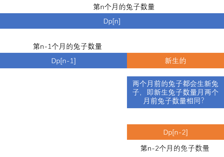
Leetcode: dynamic planning template
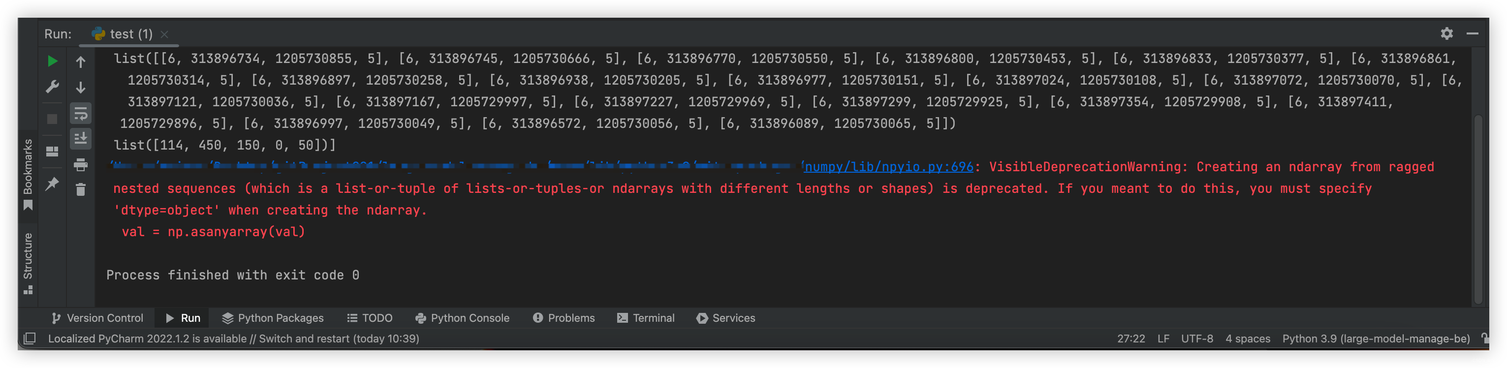
numpy之 警告VisibleDeprecationWarning: Creating an ndarray from ragged nested sequences
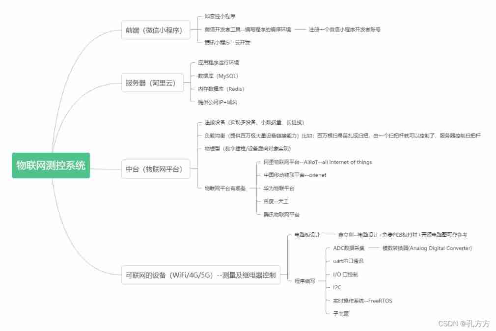
Wechat applet + Alibaba IOT platform + Hezhou air724ug built with server version system analysis

npm : 无法将“npm”项识别为 cmdlet、函数、脚本文件或可运行程序的名称。请检查名称的拼写,如果包括路径,请确保路径正确,然后再试一次。
![[home push IMessage] software installation virtual host rental tothebuddy delay](/img/e7/eb20a773e4b674962f856d179a3769.jpg)
[home push IMessage] software installation virtual host rental tothebuddy delay
随机推荐
shardingsphere动态数据源
简易版 微信小程序开发之页面跳转、数据绑定、获取用户信息、获取用户位置信息
Read a paper_ ChineseBert
Applet (continuous update)
【刷题篇】接雨水(一维)
2.14 simulation summary
Ffmpeg recording screen and screenshot
2022 tea master (intermediate) examination questions and analysis and tea master (intermediate) practical examination video
Makefile demo
Introduction to mongodb
In Net 6 project using startup cs
What can learning pytorch do?
navicat 导出数据库的表结构
Summary of electromagnetic spectrum
Some preliminary preparations for QQ applet development: make an appointment for a development account, download and install developer tools, and create QQ applet
vim 的实用操作
Write it down once Net travel management background CPU Explosion Analysis
IPv6 transition technology-6to4 manual tunnel configuration experiment -- Kuige of Shangwen network
[mathematical logic] propositional logic (propositional logic reasoning | formal structure of reasoning | inference law | additional law | simplification law | hypothetical reasoning | refusal | disju
MPLS setup experiment