当前位置:网站首页>Learnopongl notes (I)
Learnopongl notes (I)
2022-07-05 16:45:00 【Small margin, rush】
Catalog
Core mode and immediate rendering mode
Multi level fade texture Mipmap
7、 ... and 、 Coordinate system
Perspective movement - Add mouse
One 、 summary
OpenGL What is it
It is generally considered to be a API(Application Programming Interface, Application programming interface ), Contains a series of operational graphics 、 Functions of images .
OpenGL The specification specifies exactly how each function should be executed , And their output values . Actually OpenGL The developer of the library is usually the manufacturer of the graphics card .
OpenGL The library uses C Written language , It also supports the derivation of multiple languages , But its kernel is still a C library .
Core mode and immediate rendering mode
In the early OpenGL Use immediate rendering mode ,OpenGL Most of the functions of are hidden by the library , Developers have little control OpenGL Freedom of how to calculate .
Tutorial oriented OpenGL3.3 The core model of .
Expand
OpenGL A major feature of is the extension (Extension) Support for , When a graphics card company comes up with a new feature or a big optimization in rendering , It is usually implemented in the driver in an extended way .
State machine
OpenGL It's a huge state machine (State Machine): A series of variable descriptions OpenGL How to run at this moment .OpenGL The state of is usually called OpenGL Context (Context).
Two 、 window
int main()
{
    glfwInit();// initialization
    glfwWindowHint(GLFW_CONTEXT_VERSION_MAJOR, 3);
    glfwWindowHint(GLFW_CONTEXT_VERSION_MINOR, 3);
    glfwWindowHint(GLFW_OPENGL_PROFILE, GLFW_OPENGL_CORE_PROFILE);
//glfwWindowHint The first parameter of the function represents the name of the option , We can learn a lot from GLFW_ Select... From the enumeration values at the beginning ; The second parameter accepts an integer , Used to set the value of this option .

   GLFWwindow* window = glfwCreateWindow(800, 600, "LearnOpenGL", NULL, NULL);
// The width and height of the window , The name of the window
    if (window == NULL)
    {
        std::cout << "Failed to create GLFW window" << std::endl;
        glfwTerminate();
        return -1;
    }
    glfwMakeContextCurrent(window);

    glfwSetFramebufferSizeCallback(window, framebuffer_size_callback);// Callback


    return 0;
}
GLAD Is to manage OpenGL Of the function pointer , So call any OpenGL We need to initialize GLAD.
if (!gladLoadGLLoader((GLADloadproc)glfwGetProcAddress))
{
    std::cout << "Failed to initialize GLAD" << std::endl;
    return -1;
}
viewport
tell OpenGL Render window The size of the viewport (Viewport)
glViewport(0, 0, 800, 600);
glViewport The first two parameters of the function control the position of the lower left corner of the window . The third and fourth parameters control the width and height of the rendering window ( Pixels ).
When the user changes the size of the window , The viewport should also be adjusted . We can register a callback function for the window (Callback Function), It is called every time the window is resized .
void framebuffer_size_callback(GLFWwindow* window, int width, int height)
{
    glViewport(0, 0, width, height);
}
// register
glfwSetFramebufferSizeCallback(window, framebuffer_size_callback);
Render loop (Render Loop)
while(!glfwWindowShouldClose(window))
// Check once before we start each cycle GLFW Are you required to quit
// If so, the function returns true Then the rendering cycle ends
{
    processInput(window);// Detect whether a specific key is pressed

    glfwSwapBuffers(window);// Swap color buffer
    glfwPollEvents();
// Check if there are any events triggered ( For example, keyboard input 、 Mouse movement, etc )
// Update window status , And call the corresponding callback function

}
  glfwTerminate();//clearing all
  return 0;
Double buffering (Double Buffer)
There may be a problem of image flicker when using single buffer drawing . front The buffer holds the final output image , It will show on the screen ; All rendering instructions will be in after Draw on buffer . When all rendering instructions are executed , We In exchange for (Swap) Front buffer and rear buffer , In this way, the image is displayed immediately .
Input
void processInput(GLFWwindow *window)
// A window and a key as input . This function will return whether the key is being pressed .
{
    if(glfwGetKey(window, GLFW_KEY_ESCAPE) == GLFW_PRESS)
        glfwSetWindowShouldClose(window, true);
}
Rendering
All renderings (Rendering) Put the operation into the render loop , Because we want these rendering instructions to be executed every iteration of the rendering cycle .
At the beginning of each new rendering iteration, we always want to clear the screen , Otherwise, we can still see the rendering result of the last iteration , call glClear Function to clear the color buffer of the screen , Possible buffer bits are GL_COLOR_BUFFER_BIT,GL_DEPTH_BUFFER_BIT and GL_STENCIL_BUFFER_BIT. Because now we only care about the color value , So we just empty the color buffer .
glClearColor(0.2f, 0.3f, 0.3f, 1.0f);
glClear(GL_COLOR_BUFFER_BIT);
When calling glClear function , After clearing the color buffer , The entire color buffer will be filled with glClearColor The color set in .
3、 ... and 、 triangle
- Vertex array object :Vertex Array Object,VAO
- Vertex buffer object :Vertex Buffer Object,VBO
- Index buffer object :Element Buffer Object,EBO or Index Buffer Object,IBO
OpenGL Most of our work is about putting 3D Coordinates change to fit your screen 2D Pixels ,3D The coordinates change to 2D The processing of coordinates is done by OpenGL Graphics rendering pipeline management .
The first part is to put your 3D The coordinates are converted to 2D coordinate , The second part is to put 2D Coordinates change to actual colored pixels .
OpenGL Shaders are made with OpenGL Shader Language (OpenGL Shading Language, GLSL) written
Graphics rendering pipeline
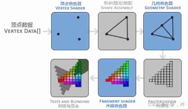
- Pass... As an array 3 individual 3D Coordinates are used as input to the graphics rendering pipeline to represent a triangle , This array is called vertex data (Vertex Data)
- Vertex shader (Vertex Shader), It takes a single vertex as input . The main purpose of vertex shaders is to transform 3D The coordinates change to another 3D coordinate
- Primitive Assembly (Primitive Assembly) Phase takes all vertices output by the vertex shader as input ( If it is GL_POINTS, So it's a vertex ), And all the points are assembled into the shape of the specified element ;
- Geometry shaders take a set of vertices in the form of primitives as input , It can construct new... By generating new vertices ( Or something else ) Elements to create other shapes .
- Grating stage (Rasterization Stage) Map the primitives to the corresponding pixels on the final screen , Generate for fragment shaders (Fragment Shader) The fragments used (Fragment). Clipping is performed before the fragment shader runs (Clipping). Clipping discards all pixels beyond your view , To improve the efficiency of execution .
- The main purpose of fragment shaders is to calculate the final color of a pixel , This is all OpenGL Where high-level effects come from . Fragment shaders contain 3D Scene data ( Like light 、 shadow 、 The color of light and so on ), This data can be used to calculate the final pixel color .
Vertex input
stay OpenGL All coordinates specified in are 3D coordinate (x、y and z),OpenGL Only when the 3D The coordinates are 3 Axes (x、y and z) It's all for -1.0 To 1.0 Only when it is within the range of .
float vertices[] = {
    -0.5f, -0.5f, 0.0f,
     0.5f, -0.5f, 0.0f,
     0.0f,  0.5f, 0.0f
};
Send it as input to the first processing stage of the graphics rendering pipeline : Vertex shader . Buffer objects through vertices (Vertex Buffer Objects, VBO) Manage this memory , It will be GPU Memory ( It is often called video memory ) Store a large number of vertices in .
unsigned int VBO;
glGenBuffers(1, &VBO);
glBindBuffer(GL_ARRAY_BUFFER, VBO);  // Any use of ( stay GL_ARRAY_BUFFER On the target ) Buffer calls are used to configure the buffer of the current binding (VBO).

glBufferData(GL_ARRAY_BUFFER, sizeof(vertices), vertices, GL_STATIC_DRAW);
// Copy the previously defined vertex data to the buffered memory
// The first parameter is the type of target buffer , The second parameter specifies the size of the transmitted data ( In bytes )
// The third parameter is the actual data we want to send .
 The fourth parameter specifies how we want the graphics card to manage the given data . It comes in three forms :

GL_STATIC_DRAW : The data will not or will hardly change .
GL_DYNAMIC_DRAW: The data will be changed a lot .
GL_STREAM_DRAW : Data changes every time it's plotted .
Vertex shader
#version 330 core
layout (location = 0) in vec3 aPos;// Set the position value of the input variable

void main()
{
    gl_Position = vec4(aPos.x, aPos.y, aPos.z, 1.0);
}
// A vector has the most 4 Weight , Each component value represents a coordinate in space
// They can go through vec.x、vec.y、vec.z and vec.w To get .
We must assign the location data to the predefined gl_Position Variable , It's behind the scenes vec4 Type of .
gl_Position The value set becomes the output of the vertex shader .
Fragment Shader
#version 330 core
out vec4 FragColor;

void main()
{
    FragColor = vec4(1.0f, 0.5f, 0.2f, 1.0f);
}
Link vertex properties

 Parse vertex data :
glVertexAttribPointer(0, 3, GL_FLOAT, GL_FALSE, 3 * sizeof(float), (void*)0);
glEnableVertexAttribArray(0);
// The second parameter specifies the size of the vertex attribute , The third parameter specifies the type of data
// The fifth parameter is called step size (Stride), It tells us the interval between successive vertex attribute groups .
// The type of the last parameter is void*, So we need to do this strange cast . It represents the offset of the starting position of the position data in the buffer (Offset).
Use glEnableVertexAttribArray, Take the vertex attribute position value as the parameter , Turn on vertex properties ; Vertex attributes are disabled by default .
Vertex array object
Vertex array object (Vertex Array Object, VAO) Can be bound like a vertex buffer object , Any subsequent vertex attribute calls are stored in this VAO in .
OpenGL The core model of requirement We use VAO, So it knows how to handle our vertex input . If we bind VAO Failure ,OpenGL Will refuse to draw anything .
// 1.  binding VAO
glBindVertexArray(VAO);
// 2.  Copy the vertex array to the buffer for OpenGL Use
glBindBuffer(GL_ARRAY_BUFFER, VBO);
glBufferData(GL_ARRAY_BUFFER, sizeof(vertices), vertices, GL_STATIC_DRAW);
// 3.  Set vertex property pointer
glVertexAttribPointer(0, 3, GL_FLOAT, GL_FALSE, 3 * sizeof(float), (void*)0);
glEnableVertexAttribArray(0);

[...]

// ..::  Draw code ( In the rendering loop ) :: ..
// 4.  Draw objects
glUseProgram(shaderProgram);
glBindVertexArray(VAO);
someOpenGLFunctionThatDrawsOurTriangle();
// When drawing multiple objects , You first have to generate / Configure all VAO( And necessary VBO And property pointers ), Then store them for later use . When we want to draw an object, we take out the corresponding VAO, Bind it , After drawing the object , Then untie VAO.
Index buffer object
Index buffer object (Element Buffer Object,EBO, Also called Index Buffer Object,IBO) It specifically stores indexes ,OpenGL Call the index of these vertices to decide which vertex to paint .
 Definition ( Not repeated ) The vertices , And the index needed to draw the rectangle
float vertices[] = {
    0.5f, 0.5f, 0.0f,   //  Upper right corner
    0.5f, -0.5f, 0.0f,  //  The lower right corner
    -0.5f, -0.5f, 0.0f, //  The lower left corner
    -0.5f, 0.5f, 0.0f   //  top left corner
};

unsigned int indices[] = { //  Pay attention to the index from 0 Start !
    0, 1, 3, //  The first triangle
    1, 2, 3  //  The second triangle
};

unsigned int EBO;
glGenBuffers(1, &EBO);// Create index buffer object
// First binding EBO And then use glBufferData Copy the index to the buffer
glBindBuffer(GL_ELEMENT_ARRAY_BUFFER, EBO);
glBufferData(GL_ELEMENT_ARRAY_BUFFER, sizeof(indices), indices, GL_STATIC_DRAW);
 The final initialization and drawing code now looks like this :
// ..::  Initialization code  :: ..
// 1.  Bind vertex array objects
glBindVertexArray(VAO);
// 2.  Copy our vertex array into a vertex buffer , for OpenGL Use
glBindBuffer(GL_ARRAY_BUFFER, VBO);
glBufferData(GL_ARRAY_BUFFER, sizeof(vertices), vertices, GL_STATIC_DRAW);
// 3.  Copy our index array into an index buffer , for OpenGL Use
glBindBuffer(GL_ELEMENT_ARRAY_BUFFER, EBO);
glBufferData(GL_ELEMENT_ARRAY_BUFFER, sizeof(indices), indices, GL_STATIC_DRAW);
// 4.  Set vertex attribute pointer
glVertexAttribPointer(0, 3, GL_FLOAT, GL_FALSE, 3 * sizeof(float), (void*)0);
glEnableVertexAttribArray(0);

[...]

// ..::  Draw code ( In the rendering loop ) :: ..
glUseProgram(shaderProgram);
glBindVertexArray(VAO);
glDrawElements(GL_TRIANGLES, 6, GL_UNSIGNED_INT, 0)


 The first parameter specifies the mode we draw , This and glDrawArrays The same as .
 The second parameter is the number of vertices we intend to paint , Fill in here 6, In other words, we need to draw 6 vertices .
 The third parameter is the type of index , Here is GL_UNSIGNED_INT.
glBindVertexArray(0);
Wireframe mode (Wireframe Mode)
To draw your triangle in wireframe mode , You can go through
glPolygonMode(GL_FRONT_AND_BACK, GL_LINE)
Four 、 Shaders
Shaders (Shader) Is running on the GPU The applet on . These applets run for a specific part of the graphics rendering pipeline .
Shader is a kind of shader called GLSL Class C Written in language .
data type
GLSL Contained in the C And most of the default basic data types in other languages :int、float、double、uint and bool.
GLSL The vector in is a vector that can contain 1、2、3 perhaps 4 Container for multiple components , The type of component can be any of the previous default base types .

The component of a vector can pass through vec.x This way to get , here x Is the first component of this vector .GLSL It also allows you to use color rgba, Or use... For texture coordinates stpq Access the same components .
Input and output
GLSL Defined in and out keyword , Vertex shaders should receive a special form of input using location This metadata specifies the input variable , So we can be in CPU Configure vertex attributes on . Another exception is fragment shaders , It needs a vec4 Color output variable , Because the clip shader needs to generate a final output color .
//vs
#version 330 core
layout (location = 0) in vec3 aPos; //  The property location value of the location variable is 0

out vec4 vertexColor; //  Assign a color output to the fragment shader

void main()
{
    gl_Position = vec4(aPos, 1.0); //  Notice how we put a vec3 As vec4 Parameters of the constructor of
    vertexColor = vec4(0.5, 0.0, 0.0, 1.0); //  Set the output variable to dark red
}

//fs
#version 330 core
out vec4 FragColor;

in vec4 vertexColor; //  Input variables from vertex shaders ( The same name 、 The same type )

void main()
{
    FragColor = vertexColor;
}
Uniform
uniform Is a global (Global). The whole situation means uniform Variables must be unique in each shader program object , And it can be accessed at any stage by any shader of the shader program .
uniform vec4 ourColor; // stay OpenGL This variable is set in the program code
This uniform It's still empty ; We haven't added any data to it yet , So let's do this . We first need to find the shader uniform Index of attribute / Position value . When we get uniform The index of / After the position value , We can update its value .
int vertexColorLocation = glGetUniformLocation(shaderProgram, "ourColor");
// use glGetUniformLocation Inquire about uniform ourColor Position value of .
// We provide shader programs and... For query functions uniform Name
// return -1 It means that the position value is not found .

glUseProgram(shaderProgram);
glUniform4f(vertexColorLocation, 0.0f, greenValue, 0.0f, 1.0f);
// adopt glUniform4f Function settings uniform value .
// Update one uniform You must use program call before glUseProgram
More properties
float vertices[] = {
    //  Location               //  Color
     0.5f, -0.5f, 0.0f,  1.0f, 0.0f, 0.0f,   //  The lower right
    -0.5f, -0.5f, 0.0f,  0.0f, 1.0f, 0.0f,   //  The lower left
     0.0f,  0.5f, 0.0f,  0.0f, 0.0f, 1.0f    //  Top
};
Since there is now more data to send to the vertex shader , We need to adjust the vertex shader , Enable it to receive color values as a vertex attribute input .
layout (location = 1) in vec3 aColor; // The attribute position value of the color variable is 1
Because we added another vertex attribute , And updated VBO Of memory , We have to reconfigure the vertex attribute pointer .
//  Location properties
glVertexAttribPointer(0, 3, GL_FLOAT, GL_FALSE, 6 * sizeof(float), (void*)0);
glEnableVertexAttribArray(0);
//  color property
glVertexAttribPointer(1, 3, GL_FLOAT, GL_FALSE, 6 * sizeof(float), (void*)(3* sizeof(float)));
glEnableVertexAttribArray(1);
Read from file
We use C++ The file stream reads the shader contents , Store in a few string In the object :
Shader(const char* vertexPath, const char* fragmentPath)
{
    // 1.  Get vertex from file path / Fragment Shader
    std::string vertexCode;
    std::string fragmentCode;
    std::ifstream vShaderFile;
    std::ifstream fShaderFile;
    //  Guarantee ifstream Object can throw an exception :
    vShaderFile.exceptions (std::ifstream::failbit | std::ifstream::badbit);
    fShaderFile.exceptions (std::ifstream::failbit | std::ifstream::badbit);
    try
    {
        //  Open file
        vShaderFile.open(vertexPath);
        fShaderFile.open(fragmentPath);
        std::stringstream vShaderStream, fShaderStream;
        //  Read the buffered contents of the file into the data stream
        vShaderStream << vShaderFile.rdbuf();
        fShaderStream << fShaderFile.rdbuf();
        //  Turn off the file processor
        vShaderFile.close();
        fShaderFile.close();
        //  Convert data flow to string
        vertexCode   = vShaderStream.str();
        fragmentCode = fShaderStream.str();
    }
    catch(std::ifstream::failure e)
    {
        std::cout << "ERROR::SHADER::FILE_NOT_SUCCESFULLY_READ" << std::endl;
    }
    const char* vShaderCode = vertexCode.c_str();
    const char* fShaderCode = fragmentCode.c_str();
next step , We need to compile and link shaders .
// 2.  Compiling shaders
unsigned int vertex, fragment;
int success;
char infoLog[512];

//  Vertex shader
vertex = glCreateShader(GL_VERTEX_SHADER);
glShaderSource(vertex, 1, &vShaderCode, NULL);
glCompileShader(vertex);
//  Print compile error ( If any )
glGetShaderiv(vertex, GL_COMPILE_STATUS, &success);
if(!success)
{
    glGetShaderInfoLog(vertex, 512, NULL, infoLog);
    std::cout << "ERROR::SHADER::VERTEX::COMPILATION_FAILED\n" << infoLog << std::endl;
};
We will put all the shader classes in the header file
class Shader
{
public:
// Program ID
unsigned int ID;
// The constructor reads and builds shaders
Shader(const GLchar* vertexPath, const GLchar* fragmentPath);
// Use / Activate program
void use();
// uniform Tool function
void setBool(const std::string &name, bool value) const;
void setInt(const std::string &name, int value) const;
void setFloat(const std::string &name, float value) const;
};
//
void use()
{
glUseProgram(ID);
}
void setFloat(const std::string &name, float value) const
{
glUniform1f(glGetUniformLocation(ID, name.c_str()), value);
}
...
// Shader program
ID = glCreateProgram();
glAttachShader(ID, vertex);
glAttachShader(ID, fragment);
glLinkProgram(ID);
// Print connection error ( If any )
glGetProgramiv(ID, GL_LINK_STATUS, &success);
if(!success)
{
glGetProgramInfoLog(ID, 512, NULL, infoLog);
std::cout << "ERROR::SHADER::PROGRAM::LINKING_FAILED\n" << infoLog << std::endl;
}
// Delete shader , They are already linked to our program , It's no longer necessary
glDeleteShader(vertex);
glDeleteShader(fragment);Shader classes use
Shader ourShader("path/to/shaders/shader.vs", "path/to/shaders/shader.fs");
...
while(...)
{
    ourShader.use();
    ourShader.setFloat("someUniform", 1.0f);
    DrawStuff();
}
5、 ... and 、 texture
Texture is a 2D picture ( There is even 1D and 3D The texture of ), Each vertex will be associated with a texture coordinate (Texture Coordinate), Used to indicate which part of the texture image should be sampled from .
Texture coordinates in x and y On the shaft , The scope is 0 To 1 Between ( Note that we are using 2D texture image ). Using texture coordinates to get texture color is called sampling (Sampling).

float texCoords[] = {
    0.0f, 0.0f, //  The lower left corner
    1.0f, 0.0f, //  The lower right corner
    0.5f, 1.0f //  upper-middle
};
Texture wrapping


The first parameter specifies the texture target ; We use 2D texture , So the texture target is GL_TEXTURE_2D. The second parameter requires us to specify the setting options and Application Texture axis . What we're going to configure is WRAP Options , And specify S and T Axis . The last parameter requires us to pass a wrapping method (Wrapping)
glTexParameteri(GL_TEXTURE_2D, GL_TEXTURE_WRAP_S, GL_MIRRORED_REPEAT);
glTexParameteri(GL_TEXTURE_2D, GL_TEXTURE_WRAP_T, GL_MIRRORED_REPEAT);
Texture filtering
As you zoom in, you will find that it is composed of countless pixels , This point is the texture pixel ;
Texture coordinates are the array you set for model vertices ,OpenGL Use the texture coordinate data of this vertex to find the pixels on the texture image , Then sample to extract the color of texture pixels .
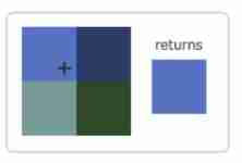
GL_NEAREST( It's also called proximity filtering ,Nearest Neighbor Filtering) yes OpenGL Default texture filtering .OpenGL The pixel closest to the texture coordinate will be selected .
GL_LINEAR( It's also called linear filtering ,(Bi)linear Filtering) It will be based on the texture pixels near the texture coordinates , Calculate an interpolation , Approximate the color between these texture pixels .
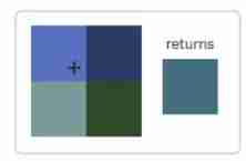
The difference :GL_NEAREST A grainy pattern , We can clearly see the pixels that make up the texture , and GL_LINEAR Can produce smoother patterns , It's hard to see a single texture pixel .GL_LINEAR Can produce more realistic output .

When zooming in (Magnify) And shrink (Minify) During operation, you can set the texture filtering options , Proximity filtering can be used when the texture is reduced , Use linear filtering when zoomed in .
glTexParameteri(GL_TEXTURE_2D, GL_TEXTURE_MIN_FILTER, GL_NEAREST);
glTexParameteri(GL_TEXTURE_2D, GL_TEXTURE_MAG_FILTER, GL_LINEAR);
Multi level fade texture Mipmap
Suppose we have a big room with thousands of objects , Every object has a texture . Some objects will be far away , But its texture will have the same high resolution as the near object . Because distant objects may produce only a few fragments ,OpenGL It's difficult to get the correct color values for these clips from high-resolution textures .
It's simply a series of texture images , The latter texture image is one-half of the former . The idea behind the multi-level fade texture is simple : The distance from the observer exceeds a certain threshold ,OpenGL Will use different multi-level fade texture , That is, the one that is most suitable for the distance of the object .
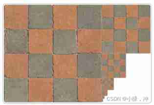
You can also use it between two different multi fade texture levels when switching between multi fade texture levels NEAREST and LINEAR Filter .
glTexParameteri(GL_TEXTURE_2D, GL_TEXTURE_MIN_FILTER, GL_LINEAR_MIPMAP_LINEAR);
glTexParameteri(GL_TEXTURE_2D, GL_TEXTURE_MAG_FILTER, GL_LINEAR);
Load and create textures
stb_image.h library
#define STB_IMAGE_IMPLEMENTATION
#include "stb_image.h"
 By defining STB_IMAGE_IMPLEMENTATION, The preprocessor will modify the header file , Let it contain only the relevant function definition source code
Generate texture
unsigned int texture;
glGenTextures(1, &texture);
// The number of textures generated , Then store them in the... Of the second parameter unsigned int Array

glBindTexture(GL_TEXTURE_2D, texture);
//  Set wrapping for the currently bound texture object 、 Filtering method
glTexParameteri(GL_TEXTURE_2D, GL_TEXTURE_WRAP_S, GL_REPEAT);
glTexParameteri(GL_TEXTURE_2D, GL_TEXTURE_WRAP_T, GL_REPEAT);
glTexParameteri(GL_TEXTURE_2D, GL_TEXTURE_MIN_FILTER, GL_LINEAR);
glTexParameteri(GL_TEXTURE_2D, GL_TEXTURE_MAG_FILTER, GL_LINEAR);

//  Load and generate textures
int width, height, nrChannels;
unsigned char *data = stbi_load("container.jpg", &width, &height, &nrChannels, 0);
if (data)
{
// Texture target (Target), Texture specifies the level of the multi-level fade texture , What is the format of texture storage .
// The fourth and fifth parameters set the width and height of the final texture

// The seventh and eighth parameters define the format and data type of the source graph .
    glTexImage2D(GL_TEXTURE_2D, 0, GL_RGB, width, height, 0, GL_RGB, GL_UNSIGNED_BYTE, data);

    glGenerateMipmap(GL_TEXTURE_2D);
}
else
{
    std::cout << "Failed to load texture" << std::endl;
}
stbi_image_free(data);// Free up image memory
Apply texture
float vertices[] = {
//     ----  Location  ----       ----  Color  ----     -  Texture coordinates  -
     0.5f,  0.5f, 0.0f,   1.0f, 0.0f, 0.0f,   1.0f, 1.0f,   //  The upper right
     0.5f, -0.5f, 0.0f,   0.0f, 1.0f, 0.0f,   1.0f, 0.0f,   //  The lower right
    -0.5f, -0.5f, 0.0f,   0.0f, 0.0f, 1.0f,   0.0f, 0.0f,   //  The lower left
    -0.5f,  0.5f, 0.0f,   1.0f, 1.0f, 0.0f,   0.0f, 1.0f    //  Top left
};
...
glVertexAttribPointer(2, 2, GL_FLOAT, GL_FALSE, 8 * sizeof(float), (void*)(6 * sizeof(float)));
glEnableVertexAttribArray(2);
Adjust the vertex shader so that it can accept vertex coordinates as a vertex attribute , And pass the coordinates to the fragment shader
layout (location = 2) in vec2 aTexCoord;
out vec2 TexCoord;
void main()
{
    TexCoord = aTexCoord;
}
 The fragment shader should then output variables TexCoord As input variable .
GLSL There is a built-in data type for texture objects , It's called a sampler (Sampler), It uses texture type as suffix
 Make a statement uniform sampler2D Add a texture to the clip shader

fs:
in vec2 TexCoord;
uniform sampler2D ourTexture;
void main()
{
    FragColor = texture(ourTexture, TexCoord);
}
// Its first parameter is the texture sampler , The second parameter is the texture coordinates .
Now all that's left is to call glDrawElements The texture was bound before , It will automatically assign the texture to the sampler of the clip shader :
glBindTexture(GL_TEXTURE_2D, texture);
glBindVertexArray(VAO);
glDrawElements(GL_TRIANGLES, 6, GL_UNSIGNED_INT, 0);
Texture units
The position value of a texture is usually called a texture unit , The main purpose of texture unit is to let us use more than one texture in shader . By assigning texture units to the sampler , We can bind multiple textures at once , As long as we first activate the corresponding texture unit .
glActiveTexture(GL_TEXTURE0); //  Activate the texture unit before binding the texture
glBindTexture(GL_TEXTURE_2D, texture);
After activating the texture unit , Next glBindTexture The function call binds the texture to the currently active texture unit , Texture units GL_TEXTURE0 Default is always activated ,OpenGL At least guarantee 16 Texture units .
#version 330 core
...

uniform sampler2D texture1;
uniform sampler2D texture2;

void main()
{
    FragColor = mix(texture(texture1, TexCoord), texture(texture2, TexCoord), 0.2);
}
We still need to edit the fragment shader to receive the final output color of another sampler. Now it is the combination of two textures .
Rendering process :
 First bind two textures to the corresponding texture unit
glActiveTexture(GL_TEXTURE0); glBindTexture(GL_TEXTURE_2D, texture1); glActiveTexture(GL_TEXTURE1); glBindTexture(GL_TEXTURE_2D, texture2);

 By using glUniform1i How to set up each sampler tells OpenGL Which texture unit does each shader sampler belong to .
ourShader.use(); //  Don't forget to set uniform Variable before activating the shader program !
glUniform1i(glGetUniformLocation(ourShader.ID, "texture1"), 0); //  Manual settings
ourShader.setInt("texture2", 1); //  Or use shader class settings
Texture upside down :OpenGL requirement y Axis
0.0The coordinates are at the bottom of the picture , But the picture y Axis0.0The coordinates are usually at the top .stbi_set_flip_vertically_on_load(true);
6、 ... and 、 Transformation
vector
The basic definition of a vector is a direction . A vector has a direction (Direction) And size (Magnitude, Also called strength or length ). Scalar (Scalar) It's just a number ( Or a vector with only one component ).
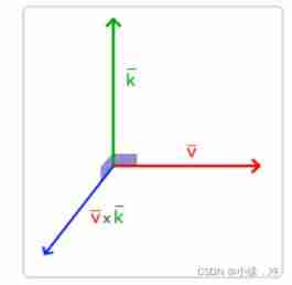
It's a strange situation that two vectors multiply . Ordinary multiplication is undefined in vectors , Because it doesn't make sense visually . But when we multiply, we have two specific situations to choose from : One is dot multiplication, the other is cross multiplication (Cross Product)
Cross riding only in 3D There is a definition in space , It needs two nonparallel vectors as input , Generate a third vector orthogonal to two input vectors .
matrix
7、 ... and 、 Coordinate system
In order to transform coordinates from one coordinate system to another , We need to use several transformation matrices , The most important ones are the models (Model)、 Observe (View)、 Projection (Projection) Three matrices .
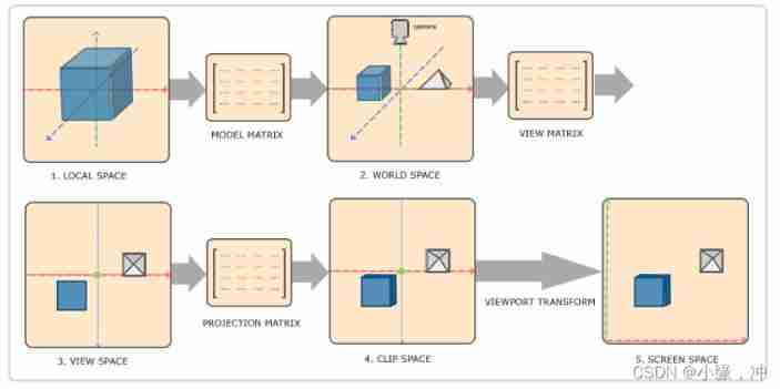
- Local coordinates are the coordinates of the object relative to the local origin , It is also the coordinate of the beginning of the object .
- The next step is to transform the local coordinates into world space coordinates , World spatial coordinates are in a larger spatial range . These coordinates are relative to the global origin of the world , They will be placed with other objects relative to the origin of the world .
- Next, we transform the world coordinates into observation space coordinates , So that each coordinate is observed from the perspective of the camera or observer .
- After the coordinates reach the observation space , We need to project it to the clipping coordinates . The clipping coordinates will be processed to -1.0 To 1.0 Within the scope of , And determine which vertices will appear on the screen .
- Last , We transform the clipping coordinates into screen coordinates , We'll use a called viewport transformation (Viewport Transform) The process of . The viewport transformation will be located in -1.0 To 1.0 The coordinates of the range are transformed from glViewport Within the range of coordinates defined by the function . The final transformed coordinates will be sent to the grating , Turn it into fragments .
Orthographic projection
glm::ortho(0.0f, 800.0f, 0.0f, 600.0f, 0.1f, 100.0f);
The first two parameters specify the left and right coordinates of the frustum , The third and fourth parameters specify the bottom and top of the frustum . Through these four parameters, we define the sizes of the near plane and the far plane , Then the fifth and sixth parameters define the distance between the near plane and the far plane . This projection matrix will be in these x,y,z Coordinates in the range of values are transformed into standardized equipment coordinates .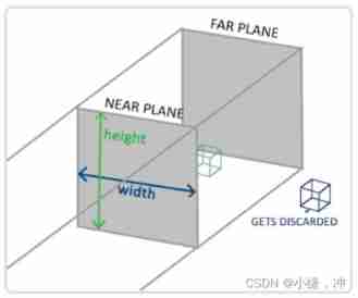
Perspective projection
Because of perspective , The two lines seem to intersect at a distance . This is exactly what perspective projection wants to imitate , It is done using perspective projection matrix .
glm::mat4 proj = glm::perspective(glm::radians(45.0f), (float)width/(float)height, 0.1f, 100.0f);
View / Aspect ratio / Flat truncated body near and far Plane
glm::perspective What you do is create a large... That defines the visual space Truncated head , Anything outside the frustum will not end up in the clipping space volume , And will be cut .

When using orthographic projection , Each vertex coordinate will be directly mapped into the clipping space without any fine perspective division .
3D
At the beginning 3D When drawing , We first create a model matrix . This model matrix contains the displacement 、 Zoom and rotate , They will be applied to the vertices of all objects , With Transformation They go to the global world space .
glm::mat4 model;
model = glm::rotate(model, glm::radians(-55.0f), glm::vec3(1.0f, 0.0f, 0.0f));

glm::mat4 view;
//  Be careful , We move the matrix in the opposite direction of the scene we want to move .
view = glm::translate(view, glm::vec3(0.0f, 0.0f, -3.0f));

glm::mat4 projection;
projection = glm::perspective(glm::radians(45.0f), screenWidth / screenHeight, 0.1f, 100.0f);

 Incoming shaders
#version 330 core
layout (location = 0) in vec3 aPos;
...
uniform mat4 model;
uniform mat4 view;
uniform mat4 projection;

void main()
{
    //  Note that multiplication should be read from right to left
    gl_Position = projection * view * model * vec4(aPos, 1.0);
    ...
}
Pass matrix into shader
int modelLoc = glGetUniformLocation(ourShader.ID, "model")); glUniformMatrix4fv(modelLoc, 1, GL_FALSE, glm::value_ptr(model));
...
Z buffer Z-buffer
GLFW Will automatically generate such a buffer for you , The depth value is stored in each segment ( As a fragment z value ), When a clip wants to output its color ,OpenGL Will compare its depth value with z Buffer for comparison , If the current clip is after other clips , It will be discarded , Otherwise... Will be overwritten . This process is called depth testing (Depth Testing), It is from OpenGL autocomplete .
Enable depth testing :
glEnable(GL_DEPTH_TEST);
Because we used depth testing , We also want to clear the depth buffer before each rendering iteration
glClear(GL_COLOR_BUFFER_BIT | GL_DEPTH_BUFFER_BIT);
8、 ... and 、 The camera
When we talk about cameras / Observe the space (Camera/View Space) When , It is to discuss the coordinates of all vertices in the scene when the camera's perspective is used as the scene origin .
Camera position
Getting the camera position is simple . The camera position is simply a vector pointing to the camera position in world space .z The axis is pointing at you from the screen . We want the camera to move backwards , We'll go along z The positive movement of the axis .
glm::vec3 cameraPos = glm::vec3(0.0f, 0.0f, 3.0f);
Camera direction
It refers to which direction the camera points . The camera is pointing at z Axis negative direction , But we want the direction vector (Direction Vector) Pointing to the camera z Affirmative direction .
glm::vec3 cameraTarget = glm::vec3(0.0f, 0.0f, 0.0f);
glm::vec3 cameraDirection = glm::normalize(cameraPos - cameraTarget);
The other vector we need is a Right vector (Right Vector), It represents the camera space x The positive direction of the axis . So let's define one Upper vector (Up Vector). Next, cross multiply the up vector and the direction vector obtained in step 2 . Now we have x Axis vectors and z Axis vector , Get a positive... Pointing to the camera y The axis vector is relatively simple : Cross multiply the right vector and the direction vector :
glm::vec3 up = glm::vec3(0.0f, 1.0f, 0.0f);
glm::vec3 cameraRight = glm::normalize(glm::cross(up, cameraDirection));

glm::vec3 cameraUp = glm::cross(cameraDirection, cameraRight);
Look At
Use this 3 An axis plus a translation vector to create a matrix , And you can multiply this matrix by any vector to transform it into that coordinate space .
All we have to do is define a camera position , A target position and a vector representing the upper vector in world space ( The upper vector we use to calculate the right vector ).
glm::mat4 view;
view = glm::lookAt(glm::vec3(0.0f, 0.0f, 3.0f),
           glm::vec3(0.0f, 0.0f, 0.0f),
           glm::vec3(0.0f, 1.0f, 0.0f));
Move freely
We first set the camera position to the previously defined cameraPos. The direction is the current position plus the direction vector we just defined . This ensures that no matter how we move , The camera will look at the direction of the target .
glm::vec3 cameraPos   = glm::vec3(0.0f, 0.0f,  3.0f);
glm::vec3 cameraFront = glm::vec3(0.0f, 0.0f, -1.0f);
glm::vec3 cameraUp    = glm::vec3(0.0f, 1.0f,  0.0f);

view = glm::lookAt(cameraPos, cameraPos + cameraFront, cameraUp);

void processInput(GLFWwindow *window)
{
    ...
    float cameraSpeed = 0.05f; // adjust accordingly
    if (glfwGetKey(window, GLFW_KEY_W) == GLFW_PRESS)
        cameraPos += cameraSpeed * cameraFront;
    if (glfwGetKey(window, GLFW_KEY_S) == GLFW_PRESS)
        cameraPos -= cameraSpeed * cameraFront;
    if (glfwGetKey(window, GLFW_KEY_A) == GLFW_PRESS)
        cameraPos -= glm::normalize(glm::cross(cameraFront, cameraUp)) * cameraSpeed;
    if (glfwGetKey(window, GLFW_KEY_D) == GLFW_PRESS)
        cameraPos += glm::normalize(glm::cross(cameraFront, cameraUp)) * cameraSpeed;
}
When we press down WASD Any one of the keys , The location of the camera will be updated accordingly . If we want to move forward or backward , Let's add or subtract the position vector from the direction vector . If we want to move left and right , We use cross multiplication to create a Right vector (Right Vector), And move along it .
At present, our moving speed is a constant .
Graphics programs and games usually track a time difference (Deltatime) Variable , It stores the time taken to render the last frame . Let's multiply all the speeds by deltaTime value . The result is , If our deltaTime It's big , It means that the rendering of the previous frame takes more time , It takes more time to balance this frame .
float deltaTime = 0.0f; //  The time difference between the current frame and the previous frame
float lastFrame = 0.0f; //  Time of last frame

float currentFrame = glfwGetTime();
deltaTime = currentFrame - lastFrame;
lastFrame = currentFrame;

void processInput(GLFWwindow *window)
{
  float cameraSpeed = 2.5f * deltaTime;
  ...
}
Perspective movement - Add mouse
In order to be able to change the perspective , We need to change... According to the input of the mouse cameraFront vector .
Euler Angle : Euler Angle (Euler Angle) It can be represented 3D Any rotating in space 3 It's worth , Pitch angle (Pitch)、 Yaw angle (Yaw) And roll angle (Roll).
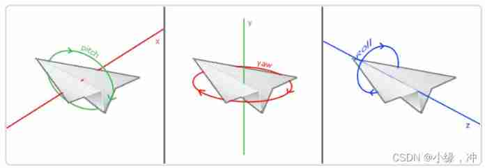
direction.x = cos(glm::radians(pitch)) * cos(glm::radians(yaw));
//  Translation notes :direction Represents the front axle of the camera (Front), This front axis is opposite to the direction vector of the second camera in the first picture in this paper
direction.y = sin(glm::radians(pitch));
direction.z = cos(glm::radians(pitch)) * sin(glm::radians(yaw));
The yaw angle and pitch angle are determined by the mouse ( Or handle ) Move to get , Horizontal movement affects the yaw angle , The vertical movement affects the pitch angle . Its principle is , Save the position of the mouse in the last frame , In the current frame, we calculate the difference between the current mouse position and the position of the previous frame . If level / The greater the vertical difference, the greater the change in pitch or yaw angle , That is, the camera needs to move more distance .
- Calculate the offset of the mouse from the previous frame .
- Add the offset to the pitch and yaw angles of the camera .
- Limit the maximum and minimum values of yaw angle and pitch angle .
- Calculate the direction vector .
glfwSetInputMode(window, GLFW_CURSOR, GLFW_CURSOR_DISABLED);// hide cursor , And capture (Capture) it

void mouse_callback(GLFWwindow* window, double xpos, double ypos);

glfwSetCursorPosCallback(window, mouse_callback);

 We must first store the mouse position of the last frame in the program , We set its initial value to the center of the screen
float lastX = 400, lastY = 300;

float xoffset = xpos - lastX;
float yoffset = lastY - ypos; //  Notice the opposite here , because y The coordinates increase from the bottom to the top
lastX = xpos;
lastY = ypos;

float sensitivity = 0.05f;
xoffset *= sensitivity;// sensitivity
yoffset *= sensitivity;

yaw   += xoffset;
pitch += yoffset;
 Add some restrictions to the camera , So the camera won't move strangely , For pitch angle , Let users not look higher than 89 The place of degree ( stay 90 The angle of view will be reversed , So we put 89 Degrees as the limit ), Similarly, it is not allowed to be less than -89 degree .
if(pitch > 89.0f)
  pitch =  89.0f;
if(pitch < -89.0f)
  pitch = -89.0f;
 Calculate the pitch angle and yaw angle to get the real direction vector
glm::vec3 front;
front.x = cos(glm::radians(pitch)) * cos(glm::radians(yaw));
front.y = sin(glm::radians(pitch));
front.z = cos(glm::radians(pitch)) * sin(glm::radians(yaw));
cameraFront = glm::normalize(front);
The zoom
Use the mouse wheel to zoom in
glfwSetScrollCallback(window, scroll_callback);// Register the callback function of the mouse wheel

void scroll_callback(GLFWwindow* window, double xoffset, double yoffset)
{
  if(fov >= 1.0f && fov <= 45.0f)
    fov -= yoffset;//yoffset The value represents the size of our vertical scroll
  if(fov <= 1.0f)
    fov = 1.0f;
  if(fov >= 45.0f)//45.0f Is the default field of view value
    fov = 45.0f;
}
We now have to upload the perspective projection matrix to every frame GPU, But now use fov Variable as its field of view :
projection = glm::perspective(glm::radians(fov), 800.0f / 600.0f, 0.1f, 100.0f);
glossary
- GLAD: An extended loading Library , Used to load and set all for us OpenGL A function pointer
- viewport (Viewport): We need to render the window
- Graphics pipeline (Graphics Pipeline): The whole process of a vertex before it is rendered as a pixel
- Shaders (Shader): A small program running on a graphics card
- Vertex array object (Vertex Array Object): Store buffer and vertex attribute States
- Vertex buffer object (Vertex Buffer Object): A buffer object that calls the video memory and stores all vertex data for the video card
- Index buffer object (Element Buffer Object): A buffer object that stores indexes for indexed drawing
- Texture wrapping (Texture Wrapping): Defines a method when texture vertices are out of range (0, 1) When you specify OpenGL How to sample texture patterns
- Texture filtering (Texture Filtering): Defines a method of specifying when there are multiple texture elements to choose OpenGL How to sample texture patterns
- Multi level fade texture (Mipmaps): Some reduced versions of the stored material , The appropriate size of the material will be used according to the distance from the observer
- Texture units (Texture Units): By binding textures to different texture units, multiple textures are allowed to render on the same object
- GLM: One for OpenGL Create a math library
- Local space (Local Space): The initial space of an object . All coordinates are relative to the origin of the object
- World space (World Space): All coordinates are relative to the global origin
- Observe the space (View Space): All coordinates are viewed from the camera's perspective
- Cutting space (Clip Space): This space applies projection . This space should be the final space of vertex coordinates , As the output of vertex shader
- Screen space (Screen Space): All coordinates are observed from the screen perspective
- LookAt matrix : A special type of observation matrix , It creates a coordinate system , All coordinates are rotated or translated according to the user who is observing the target from one position
边栏推荐
- 2020-2022两周年创作纪念日
- Win11如何给应用换图标?Win11给应用换图标的方法
- Single merchant v4.4 has the same original intention and strength!
- DeSci:去中心化科学是Web3.0的新趋势?
- Global Data Center released DC brain system, enabling intelligent operation and management through science and technology
- 漫画:什么是服务熔断?
- Cheer yourself up
- 数据湖(十四):Spark与Iceberg整合查询操作
- File operation --i/o
- "21 days proficient in typescript-3" - install and build a typescript development environment md
猜你喜欢

Explain in detail the functions and underlying implementation logic of the groups sets statement in SQL

Jarvis OJ 简单网管协议

【 brosser le titre 】 chemise culturelle de l'usine d'oies
ES6 deep - ES6 class class

Hiengine: comparable to the local cloud native memory database engine
If you can't afford a real cat, you can use code to suck cats -unity particles to draw cats

Binary tree related OJ problems

Domestic API management artifact used by the company

數據訪問 - EntityFramework集成
Jarvis OJ 远程登录协议
随机推荐
Is it safe for Guotai Junan to open an account online
File operation --i/o
一些认知的思考
Seaborn绘制11个柱状图
StarkWare:欲构建ZK“宇宙”
Android privacy sandbox developer preview 3: privacy, security and personalized experience
【组队 PK 赛】本周任务已开启 | 答题挑战,夯实商品详情知识
【 brosser le titre 】 chemise culturelle de l'usine d'oies
Google Earth engine (GEE) -- a brief introduction to kernel kernel functions and gray level co-occurrence matrix
《MongoDB入门教程》第04篇 MongoDB客户端
One click installation script enables rapid deployment of graylog server 4.2.10 stand-alone version
tf. sequence_ Mask function explanation case
Win11提示无法安全下载软件怎么办?Win11无法安全下载软件
【学术相关】多位博士毕业去了三四流高校,目前惨不忍睹……
Practice independent and controllable 3.0 and truly create the open source business of the Chinese people
深潜Kotlin协程(二十一):Flow 生命周期函数
Data verification before and after JSON to map -- custom UDF
Sentinel-流量防卫兵
Apple 已弃用 NavigationView,使用 NavigationStack 和 NavigationSplitView 实现 SwiftUI 导航
漫画:什么是MapReduce?