当前位置:网站首页>Matlab generates DSP program -- official routine learning (6)
Matlab generates DSP program -- official routine learning (6)
2022-07-02 09:54:00 【Quikk】
Matlab Generate dsp Program —— Official routine learning (6)
The official link : The official link
ccs Program is model : Models and procedures
There are Chinese marks when I read the program and the program , It may seem easier .
IPC signal communication
One 、 Main purpose
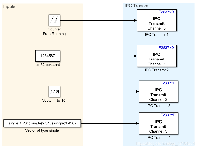
This routine uses IPC Conduct 2837xD Communication between the two cores ,CPU1 Four are enabled IPC Channel for data transmission . Register transfer should be used here ( After seeing the program, I found that it was repackaged IPC, Or use memory sharing , And the encapsulation is more ingenious. It is recommended to read the **IPCInit()** function ), The data transmitted at one time shall not exceed 32 position .
| Channel number | Deliver content | Sampling time |
|---|---|---|
| IPC0 | 16 An integer (0-2^16-1 loop )[16 bits] | 1 |
| IPC1 | 32 Bit unsigned integer number (1234567)[32 bits] | 0.5 |
| IPC2 | 1×10 matrix (1 2 3 … 10)[16 bits] | 0.1 |
| IPC3 | Single-precision floating-point (1.234 2.345 3.456)[32 bits] | 0.01 |
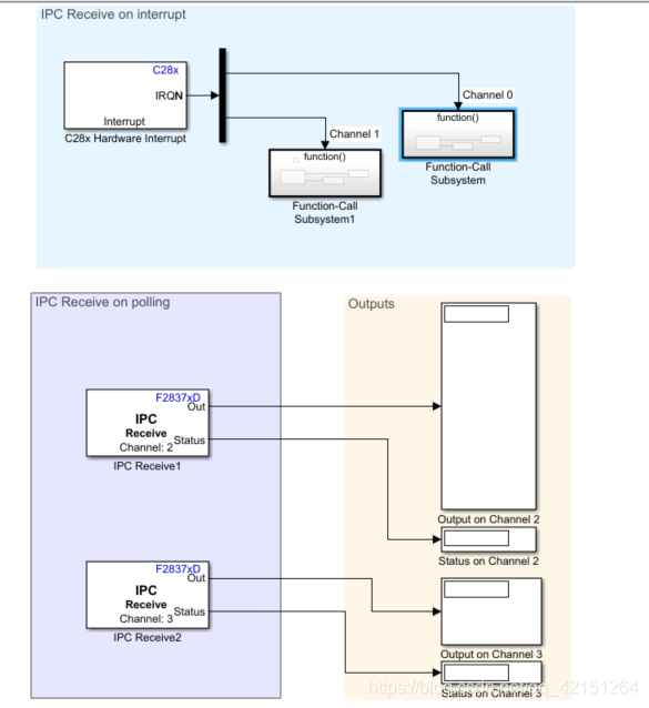
CPU2 Chinese vs CPU1 Receive the transmitted data .
IPC0 and IPC1 The transmitted data is transmitted by IPC0 Break and IPC1 Interrupt to receive .
IPC2 and IPC3 The transmitted data is obtained by the system polling .
therefore IPC0 and IPC1 The sampling time of the receiving module is determined by the interrupt function , stay IPC Receive Set in the for -1( That is, inherit the sampling time of the previous level )
IPC2 and IPC3 The sampling time is the same as CPU1 The settings of are exactly the same .
Two 、 Program analysis
1. CPU1 Program
void rt_OneStep(void)
// Every time 0.01s Enter once   Sampling time :IPC0-1 IPC1-0.5 IPC2-0.1 IPC3-0.01s
// According to this logic
//IPC3 It should be interrupted once every time you enter
//IPC2  Every time you enter 10 One at a time
//IPC1  Every time you enter 50 One at a time
//IPC0  Every time you enter 100 One at a time

{

  boolean_T eventFlags[4];
  int_T i;

  /* Check base rate for overrun */
  if (isRateRunning[0]++) {
                            //1.{0 0 0} Turn into {1 0 0 0}
    IsrOverrun = 1;
    isRateRunning[0]--;                /* allow future iterations to succeed*/
    return;
  }

  /* * For a bare-board target (i.e., no operating system), the rates * that execute this base step are buffered locally to allow for * overlapping preemption. The generated code includes function * writeCodeInfoFcn() which sets the rates * that need to run this time step. The return values are 1 and 0 * for true and false, respectively. */
  c2837xd_ipc_cpu1_tx_SetEventsForThisBaseStep(eventFlags);      //TID[1-3] Assign a value to eventFlags[1-3]
  enableTimer0Interrupt();
  c2837xd_ipc_cpu1_tx_step0();                               //TD[1-3] Self adding ,TD[1] stay 0-9 loop  TD[2] stay 0-49 loop  TD[3] stay 0-99 loop

  /* Get model outputs here */
  disableTimer0Interrupt();
  isRateRunning[0]--;                                        //{1 0 0} Turn into {0 0 0 0}
  for (i = 1; i < 4; i++)
  {

    if (eventFlags[i])             //eventFlags[i] Not for 0 Get into if //1.{0 2 2 2}
    {

      if (need2runFlags[i]++)      //need2runFlags[i] Not for 0 Get into if {0 1 1 1}
      {

        IsrOverrun = 1;
        need2runFlags[i]--;            /* allow future iterations to succeed*/
        break;
      }
    }
  }

  for (i = 1; i < 4; i++)
  {

    if (isRateRunning[i])
    {

      /* Yield to higher priority*/
      return;
    }

    if (need2runFlags[i])
    {

      isRateRunning[i]++;                 //{0 1 0 0}
      enableTimer0Interrupt();

      /* Step the model for subrate "i" */
      switch (i)
      {

       case 1 :
        c2837xd_ipc_cpu1_tx_step1();

        /* Get model outputs here */
        break;

       case 2 :
        c2837xd_ipc_cpu1_tx_step2();

        /* Get model outputs here */
        break;

       case 3 :
        c2837xd_ipc_cpu1_tx_step3();

        /* Get model outputs here */
        break;

       default :
        break;
      }

      disableTimer0Interrupt();
      need2runFlags[i]--;
      isRateRunning[i]--;
    }
  }
}
The above part is Timer0 The main program in the interrupt function , This program realizes the allocation of sampling time . namely
Every time 0.01s Enter once Timer0 Interrupt function Sampling time :IPC0-1 IPC1-0.5 IPC2-0.1 IPC3-0.01s
According to this logic
IPC3 It should be interrupted once every time you enter
IPC2 Every time you enter 10 One at a time
IPC1 Every time you enter 50 One at a time
IPC0 Every time you enter 100 One at a time
Understanding this mechanism requires understanding a structure ,c2837xd_ipc_cpu1_tx_M:
struct tag_RTM_c2837xd_ipc_cpu1_tx_T {

  const char_T *errorStatus;
  /* * Timing: * The following substructure contains information regarding * the timing information for the model. */
  struct
  {

    struct
    {

      uint8_T TID[4];
    } TaskCounters;
  } Timing;
};
Among them TID[4] It is the work of task time allocation , here IPC0-IPC3 There are four tasks , And the sampling time of the four tasks is different , therefore TID There are four elements in the array . You can reason , When there are more different sampling times , There will also be more elements .
TID[0] Corresponding IPC3 The sampling time of (0.01 s)
TID[1] Corresponding IPC2 The sampling time of (0.1 s)
TID[2] Corresponding IPC1 The sampling time of (0.5 s)
TID[3] Corresponding IPC0 The sampling time of (1 s)
Just imagine , I want to control IPC2 Every time 0.1 s Do it once , Is it just a counter , One but IPC3 Ten times , Does that mean the past 0.1 s, Then you can execute IPC2. Therefore, the procedure stipulates :TD[1] stay 0-9 loop ,TD[2] stay 0-49 loop ,TD[3] stay 0-99 loop .
By the way ,Simulink It is still beneficial to set the step size in to automatic , Because each sampling time must be an integral multiple of the step size . The generated code also reflects from the side Simulink The calculation method in .
TID The elements in will be in each step (IPC3) Self adding in the program 1.c2837xd_ipc_cpu1_tx_SetEventsForThisBaseStep(eventFlags) This function will judge TID[x] Is it equal to 0( be equal to 0 It means that a counting cycle has been completed ). Once the counting cycle is reached, the corresponding eventFlags Set the position to 1. This is through switch Function to select the execution function .
(eg: When TID[1] It's done once 0-9 The counting period of , Will eventFlags[1] The element in is set to 1, And then through switch Function execution **step1()** function ) The problem that has been bothering for several days has finally been solved ..( If you encounter logical problems, you can use DEBUG or C Language programming for simulation )
This timing control method is more interesting , Look at this function : Every 0.5 s Flip once LED The operation of .
while(1)
{

	LED =1;
	DELAY_MS(500);
	LED=0;
	DELAY_MS(500);
}
let me put it another way , From the perspective of time sequence , Am I setting up a timer . Once the time is up 0.5 s I'm right LED Do one operation . This is the view of the timing of generating code . When writing programs with us , Somewhat different . This will be us converting the code into Simulimk Model time , Things to pay attention to .
CPU2 The program in the program is to receive interrupts and polling , Nothing special .
3、 ... and 、 Generate structure records in code
When you look at the program , Be sure to compare these structures with simulink Take a closer look at the function parameters in .
1) The structure that controls the timing of the model , Instantiate objects c2837xd_ipc_cpu1_tx_M
struct tag_RTM_c2837xd_ipc_cpu1_tx_T {

  const char_T *errorStatus;
  struct
  {

    struct
    {

      uint8_T TID[4];
    } TaskCounters;
  } Timing;
};
// The structure that controls the timing of the model
// Alias :RT_MODEL_c2837xd_ipc_cpu1_tx_T
// Instantiate objects :c2837xd_ipc_cpu1_tx_M
2) Module signal structure , Instantiate objects :c2837xd_ipc_cpu1_tx_B
typedef struct {

  uint16_T Output;             /* '<S1>/Output' */
} B_c2837xd_ipc_cpu1_tx_T;
// Module signal structure
// Instantiate objects :c2837xd_ipc_cpu1_tx_B
3) Module state structure , Instantiate objects :c2837xd_ipc_cpu1_tx_DW
typedef struct {
  uint16_T Output_DSTATE;     /* '<S1>/Output' */
} DW_c2837xd_ipc_cpu1_tx_T;
4) Module related parameter registers , Instantiate objects :c2837xd_ipc_cpu1_tx_P( Everything in this function is related to the module . What we see Simulink Modules are also encapsulated , You can drag and drop directly , When it comes to program , The bottom layer of each module needs to be re implemented )
struct P_c2837xd_ipc_cpu1_tx_T_ {

  uint16_T WrapToZero_Threshold;       /* Mask Parameter: WrapToZero_Threshold //65535 = 2^16-1 * Referenced by: '<S3>/FixPt Switch'*/
     // Obviously and IPC0 The transfer of (0-2^16-1) It's about numbers , This is the maximum .

  real32_T Vectoroftypesingle_Value[3];  //float 32 position
    //{1.234F 2.345F 3.456F}
    //IPC3 Single precision number transmitted
                                        /* Expression: [single(1.234) single(2.345) single(3.456)] * Referenced by: '<Root>/Vector of type single'*/

  uint32_T uin32constant_Value;         //32 position
    // 1234567U
    // IPC1 The transfer of 32 Bit unsigned integer number
    									/* Computed Parameter: uin32constant_Value * Referenced by: '<Root>/uin32 constant' */
  uint16_T Constant_Value;             // once   Add to 2^16-1  when , You need to change the value of the counter to 0. This function represents this value .
    // 0U
    //IPC0 Lower limit of transmission value
    									 /* Computed Parameter: Constant_Value * Referenced by: '<S3>/Constant' */
  uint16_T Vector1to10_Value[10];
    // { 1U, 2U, 3U, 4U, 5U, 6U, 7U, 8U, 9U, 10U },
    //IPC2 The value transmitted
    									 /* Computed Parameter: Vector1to10_Value * Referenced by: '<Root>/Vector 1 to 10 ' */
  uint16_T Output_InitialCondition;
    // 0U
                                         /* Computed Parameter: Output_InitialCondition * Referenced by: '<S1>/Output' */
  uint16_T FixPtConstant_Value;
    //1U
    									 /* Computed Parameter: FixPtConstant_Value * Referenced by: '<S2>/FixPt Constant' */
};
The official comments above are in Simulink Each element of the main interface , This should be Subsystem( Subfunctions ) That is, the bottom layer of the package .
This IPC The transfer function is well encapsulated , I hope to have the opportunity to transplant it into my own code .
边栏推荐
- Read Day5 30 minutes before going to bed every day_ All key values in the map, how to obtain all value values
- C语言之最小数
- Junit5 支持suite的方法
- Bugkuctf-web21 (detailed problem solving ideas and steps)
- cmake的命令-官方文档
- Matlab生成dsp程序——官方例程学习(6)
- 2837xd 代码生成——补充(2)
- Because of hard work, the fruit goes with fate
- 每天睡前30分钟阅读Day6_Day6_Date_Calendar_LocalDate_TimeStamp_LocalTime
- 上班第一天的报错(Nessus安装winpcap报错)
猜你喜欢
阿里云ack介绍

Idea view bytecode configuration

【UE5】动画重定向:如何将幻塔人物导入进游戏玩耍

Read Day6 30 minutes before going to bed every day_ Day6_ Date_ Calendar_ LocalDate_ TimeStamp_ LocalTime
2837xd Code Generation - stateflow (4)
2837xd code generation - stateflow (1)

Attack and defense world web advanced area unserialize3

Personal experience & blog status
Introduction et prévention des essais de pénétration
Read 30 minutes before going to bed every day_ day4_ Files
随机推荐
QT signal slot summary -connect function incorrect usage
2837xd 代码生成——StateFlow(1)
Junit5 支持suite的方法
在SQL注入中,为什么union联合查询,id必须等于0
ZK configuration center -- configuration and use of config Toolkit
Inverter Simulink model -- processor in the loop test (PIL)
c语言编程题
Off grid control of three-phase inverter - PR control
TD联合Modelsim进行功能仿真
Ckeditor 4.10.1 upload pictures to prompt "incorrect server response" problem solution
Because of hard work, the fruit goes with fate
Int to string, int to qstring
go语言入门
web安全与防御
Thinkphp5 how to determine whether a table exists
Matlab代码生成之SIL/PIL测试
BugkuCTF-web16(备份是个好习惯)
CKEditor 4.10.1 上传图片提示“不正确的服务器响应” 问题解决
每天睡觉前30分钟阅读_day3_Files
攻防世界-Web进阶区-unserialize3