当前位置:网站首页>STM32---IIC
STM32---IIC
2022-07-05 08:16:00 【chen_ bx】
STM32---IIC
IIC Software simulation
Hardware IIC You need to read the chip manual to use the specified multiplexing port . adopt stm32 control GPIO Mouth simulation IIC sequential , Just any two routes GPIO To control IIC.
Code foreword
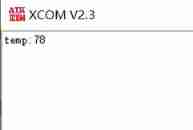
Realization IIC Reading and writing EEPROM stay EEPROM 0X18 Write a byte of data to the address of 78.
Use EEPROM model AT24C02 common 256 byte , Be careful not to exceed the address range when using .
For details, please refer to IIC Timing and AT24C02 manual
Analog timing
GPIO initialization
The following is a IIC.h Macro definitions and declarations in header files SCL Line selection PB6;SDA Line selection PB7
//iic.h Documents in
#ifndef __IIC_H
#define __IIC_H

#include "stm32f10x.h"

#define IIC_POST GPIOB
#define IIC_SCL GPIO_Pin_6
#define IIC_SDA GPIO_Pin_7

//IO Direction setting
#define SDA_IN() {
      GPIOB->CRL&=0X0FFFFFFF;GPIOB->CRL|=(u32)8<<28;}
#define SDA_OUT() {
      GPIOB->CRL&=0X0FFFFFFF;GPIOB->CRL|=(u32)3<<28;}

#define IIC_SDA_1 GPIO_SetBits(IIC_POST,IIC_SDA)
#define IIC_SDA_0 GPIO_ResetBits(IIC_POST,IIC_SDA)

#define IIC_SCL_1 GPIO_SetBits(IIC_POST,IIC_SCL)
#define IIC_SCL_0 GPIO_ResetBits(IIC_POST,IIC_SCL)

#define IIC_SDA_READ GPIO_ReadInputDataBit(IIC_POST,IIC_SDA)

void IIC_GPIO_Cfg(void);
void IIC_STOP(void);
void IIC_START(void);
void IIC_NACK(void);
void IIC_ACK(void);
u8 IIC_Read_Byte(void);
void IIC_WriteByte(uint8_t data);
u8 IIC_Wait_Ack(void);

#endif /* __IIC_H */
//iic.c Documents in
void IIC_GPIO_Cfg()
{

	GPIO_InitTypeDef GPIO_InitStruct;
	RCC_APB2PeriphClockCmd(RCC_APB2Periph_GPIOB,ENABLE);

	GPIO_InitStruct.GPIO_Mode=GPIO_Mode_Out_OD;
	GPIO_InitStruct.GPIO_Pin=IIC_SCL|IIC_SDA;
	GPIO_InitStruct.GPIO_Speed=GPIO_Speed_50MHz;
	GPIO_Init(IIC_POST, &GPIO_InitStruct);
	GPIO_SetBits(IIC_POST,IIC_SCL|IIC_SDA); 	//PB6,PB7  High output

}
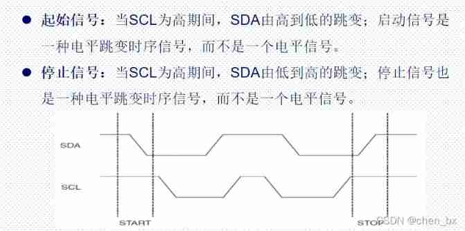
Start signal and stop signal
//iic.c Documents in
/* *brief:  Software IIC Analog transmission start signal  */
void IIC_START()
{

	SDA_OUT()	//SDA Line out
	IIC_SDA_1;	//SDA Output high level
	IIC_SCL_1;	//SCL Output high level
	delay_us(5);
	IIC_SDA_0;	//SDA Output low level
	delay_us(5);
	IIC_SCL_0;	//SCL Output low level
	delay_us(5);
}

/* *brief:  Software IIC Analog send stop signal  */
void IIC_STOP()
{

	SDA_OUT();	//sda Line out
	IIC_SCL_0;	//SCL Output low level
	IIC_SDA_0;	//SDA Output low level
 	delay_us(4);
	IIC_SCL_1; 	//SCL Output high level
	IIC_SDA_1;	//SDA Output high level
	delay_us(4);
}
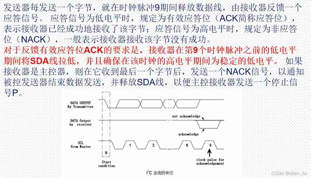
The reply 、 Non reply and waiting for reply
//iic.c Documents in

void IIC_NACK()
{

	SDA_OUT();
	IIC_SCL_0;
	IIC_SDA_1;
	delay_us(2);
	IIC_SCL_1;
	delay_us(2);
	IIC_SCL_0;
}

void IIC_ACK()
{

	SDA_OUT();
	IIC_SCL_0;
	IIC_SDA_0;
	delay_us(2);
	IIC_SCL_1;
	delay_us(2);
	IIC_SCL_0;
}

// Waiting for the answer signal to arrive
// Return value :1, Failed to receive response
// 0, Received response successfully
u8 IIC_Wait_Ack(void)
{

	u8 ucErrTime=0;
	SDA_IN();      //SDA Set to input
	IIC_SDA_1;
	delay_us(2);
	IIC_SCL_1;
	delay_us(2);
	while(IIC_SDA_READ)
	{

		ucErrTime++;
		if(ucErrTime>250)
		{

			IIC_STOP();
			return 1;
		}
	}
	IIC_SCL_0;// Clock output 0
	return 0;
}
Reading and writing 1 Bit byte function
//iic.c Documents in
u8 IIC_Read_Byte(void)
{

	SDA_IN();
	u8 i;
	u8 value=0;
	for(i=0;i<8;i++){

		value <<=1;
		IIC_SCL_1;
		delay_us(5);
		if(IIC_SDA_READ){

			value++;
		}
		IIC_SCL_0;
		delay_us(5);
	}
	return value;
}

void IIC_WriteByte(u8 data)
{

	SDA_OUT();
	u8 i;
	for(i=0;i<8;i++)
	{

		if(data &0x80){

			IIC_SDA_1;
		}
		else{

			IIC_SDA_0;
		}
		delay_us(5);
		IIC_SCL_1;
		delay_us(5);
		IIC_SCL_0;
		if(i==7)
		{

			IIC_SDA_1;
		}
		data <<=1;
		delay_us(5);
	}
}
AT24C02
AT24C02 Address
The address is 1010+A2+A1+A0+ Read write bit
10100000 by AT20C02 Write the address
10100001 Read the address as 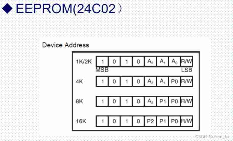
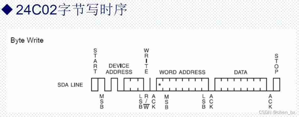
AT20C02 Write timing
AT24C02 Reading sequence
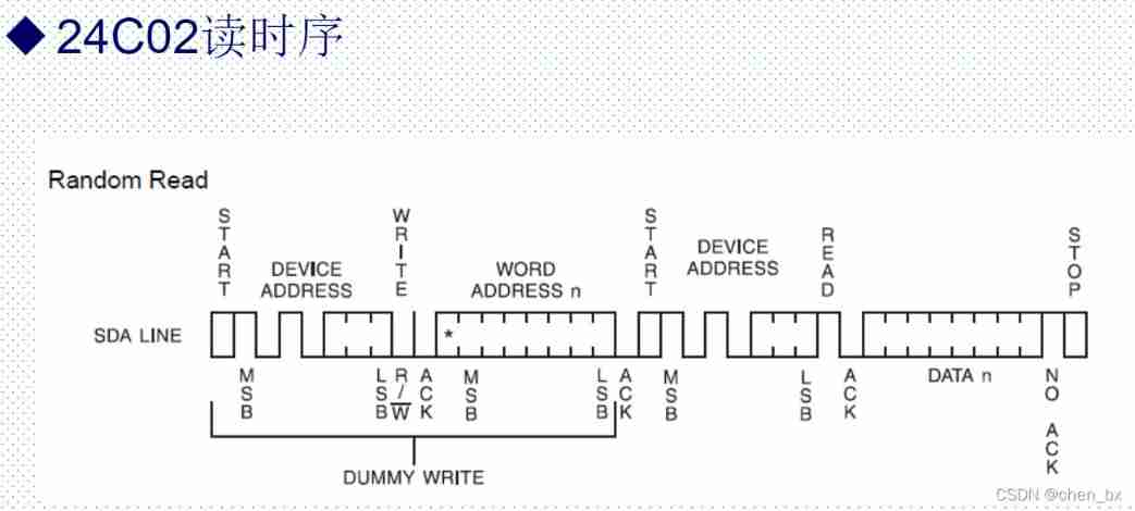
Write the following code according to the read-write address and read-write sequence :
//AT24C02 The header file
#ifndef __24C02_H
#define __24C02_H
#include "stm32f10x.h"

#define EEPROM_ADDR 0xA0

u8 AT24CXX_ReadOneByte(u8 addr);
void AT24C02_WriteByte(u8 addr,u8 data);
#endif /* __24C02_H */
//AT24C02 The source file
#include "24c02.h"
#include "IIC.h"
#include "delay.h"


// stay AT24CXX Read a data at a given address
//addr: The address to start reading
// Return value  : Data read
u8 AT24CXX_ReadOneByte(u8 addr)
{

	u8 temp=0;
    IIC_START();
	IIC_WriteByte(0XA0);   // Send device address 0XA0, Writing data

	IIC_Wait_Ack();
    IIC_WriteByte(addr);   // Sending address
	IIC_Wait_Ack();
	IIC_START();
	IIC_WriteByte(0XA1);           // Enter receive mode
	IIC_Wait_Ack();
    temp=IIC_Read_Byte();
    IIC_STOP();// Create a stop condition
	return temp;
}

// stay AT24CXX Write a data to the specified address
//addr : The destination address of the write data
//data: The data to be written
void AT24C02_WriteByte(u8 addr,u8 data)
{

	// Send the start signal
	IIC_START();

	// send out 24C02 Device address
	IIC_WriteByte(0xA0);

	// Wait for the slave device to answer
	IIC_Wait_Ack();

	// Send to write 24C02 An address of
	IIC_WriteByte(addr);

	// Wait for the slave device to answer
	IIC_Wait_Ack();

	// Send byte
	IIC_WriteByte(data);

	// Wait for the slave device to answer
	IIC_Wait_Ack();

	IIC_STOP();// Create a stop condition
	delay_ms(10);

}
Main function code
#include "stm32f10x.h"
#include "usart.h"
#include "delay.h"
#include "IIC.h"
#include "24c02.h"
#include <stdio.h>
/************************************************ * 06 IIC *  author : Mango Chen  *  date :2022.2.9 *  Content :iic Driver writing  *  Based on punctual atomic Elite Edition and reference documents  ************************************************/
u8 temp=0;

int main(void)
{


	Usart_Init();
	delay_init();
	IIC_GPIO_Cfg();
	AT24C02_WriteByte(18,78);
	delay_us(5);
	temp=AT24CXX_ReadOneByte(18);
		printf("temp:%d\n",temp);
	while(1){


		}
}
Program run results
边栏推荐
- Installation and use of libjpeg and ligpng
- Buildroot system for making raspberry pie cm3
- Bluetooth hc-05 pairing process and precautions
- Detailed explanation of pragma usage
- Consul安装
- Management and use of DokuWiki
- Weidongshan Internet of things learning lesson 1
- Measurement fitting based on Halcon learning [II] meaure_ pin. Hdev routine
- STM32 virtualization environment of QEMU
- Halcon's practice based on shape template matching [2]
猜你喜欢
Programming knowledge -- basis of C language

MySQL MHA high availability cluster
OC and OD gate circuit
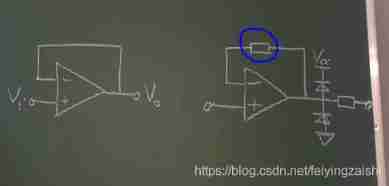
Hardware 3 -- function of voltage follower
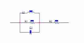
Talk about the function of magnetic beads in circuits
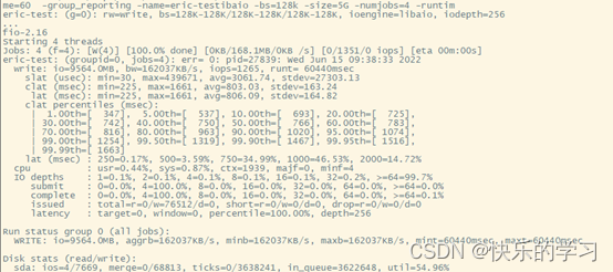
FIO测试硬盘性能参数和实例详细总结(附源码)
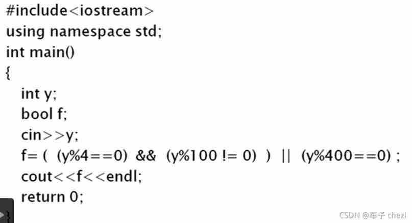
Why is 1900 not a leap year
![Halcon's practice based on shape template matching [1]](/img/68/206eed7502fbf108a929aa9365b1ae.jpg)
Halcon's practice based on shape template matching [1]
Compilation warning solution sorting in Quartus II
1-stm32 operation environment construction
随机推荐
Stablq of linked list
Connection mode - bridge and net
Bootloader implementation of PIC MCU
Detailed summary of FIO test hard disk performance parameters and examples (with source code)
Sizeof (function name) =?
Take you to understand the working principle of lithium battery protection board
Design a clock frequency division circuit that can be switched arbitrarily
Tailq of linked list
Halcon's practice based on shape template matching [2]
Soem EtherCAT source code analysis I (data type definition)
Consul installation
VESC Benjamin test motor parameters
Volatile of C language
Why is 1900 not a leap year
Classic application of MOS transistor circuit design (2) - switch circuit design
Network communication process
Various types of questions judged by prime numbers within 100 (C language)
General makefile (I) single C language compilation template
FIO测试硬盘性能参数和实例详细总结(附源码)
WiFi wpa_ Detailed description of supplicant hostpad interface