当前位置:网站首页>Take you to understand the working principle of lithium battery protection board
Take you to understand the working principle of lithium battery protection board
2022-07-05 08:09:00 【Learning notes of hardware Xiaobai】
Users who have removed mobile phones or tablets , I should have noticed , In the lithium battery part of mobile phones or tablets , There is a soft circuit board wrapped in plastic film at the upper end ( Different battery sizes , The size of the circuit board is also different ). Uncover the plastic film , You'll find that , Many components are arranged on it .
Maybe someone will ask , What is the function of this board ? Actually , Battery module , Without this circuit board , No one dares to use it !
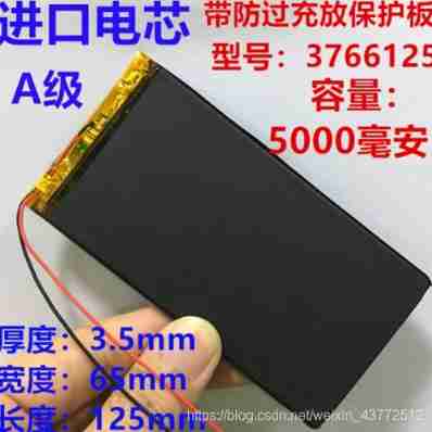
About the charge and discharge of lithium batteries , We learned chemistry in high school , It mainly depends on the movement of ions at the positive and negative poles . During charging and discharging , Ions are intercalated and de intercalated back and forth between the poles . When charging , Positive electrode will generate lithium ion , Ions are embedded and removed from the positive electrode and enter the negative electrode through the electrolyte , The negative electrode is in a lithium rich state . Discharge is the opposite . However, without the protective plate in the above figure , That is, overcharge and over discharge are likely to occur . Overcharge means too much positive ion transfer , Excessive discharge means too much negative ion transfer .
Whether the battery is overcharged or discharged , It does great harm to the battery , At the same time, it also brings potential harm to users . therefore , In order to avoid overcharge and discharge of the battery , Battery manufacturers often add such a protective plate above the battery , To avoid overcharging , The occurrence of the impact of over discharge on battery damage .
It is also due to the existence of circuit protection board , Make the lithium battery in normal use , It is difficult to overcharge and discharge . Usually , The end voltage of lithium battery charging is 4.2V, That is, the battery voltage when the battery is full is 4.2V. The protection voltage set on the circuit board is often higher than this , Some for 4.5V, When the voltage of the rechargeable battery exceeds 4.5V That is, overcharge . The cut-off voltage of discharge is 3.0V, The protection voltage set on the circuit board is lower than this , Some for 2.8V, When due to accidental discharge, put 2.8V following , At this time, it is over release .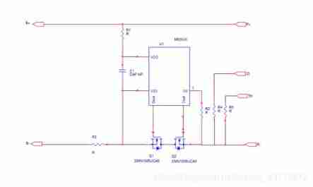
The diagram shows the design of the simple circuit board schematic diagram I drew , It's too simple .P+,P- For... On the battery connector VBAT+ And VBAT- That is, the power supply mainly in direct contact with the outside world ( The red and black lines in Figure 1 ).U1 To control IC chip . According to the change of external voltage , Make a judgment , Then open or close Q1,Q2 MOS tube , To ensure the normal operation and disconnection of the circuit .B+,B- It is the positive and negative poles of the battery cell .ID And TH Are optional , Not every battery protection board has .ID aspect ,MCU By reading the ID The resistance value of the pin resistance is used to know the type information of the battery .TH Terminated is a NTC resistance , according to NTC voltage , utilize ADC transformation , The final corresponding temperature value can be obtained , To ensure that the battery can stop charging and shut down when it is hot .
Let's talk about , The battery is in different states , The working condition of the circuit board :
1. Normal working condition
In normal working condition , In circuit U1 Of ”CO” And “DO” High level output , Two MOS The tubes are normally connected . Constitute a complete circuit , The battery can be charged and discharged normally . And MOS The on resistance of the tube is very small , stay 10 Milliohm or so . Its on resistance has little effect on the performance of the circuit .
2. Overcharge protection
The battery charging process is divided into three stages , Trickle charging respectively , Constant current charging and constant voltage charging . Trickle charging means charging to make the cell voltage meet the required voltage in the specification , It's usually 3V, The current of this process is very small . Wait until the battery voltage reaches 3.0V in the future , Then enter constant current charging , At this time, the current is constant , The voltage keeps increasing . When the voltage value increases to 4.2V when , Convert to constant voltage charging , At this time, the current will be smaller and smaller until it is full .( The voltage value inside varies according to the requirements , The voltage value is also slightly different )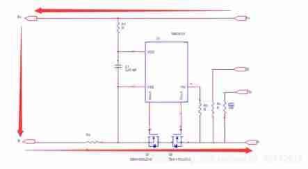
The battery is in the process of charging , If the charging circuit loses control accidentally , Make the cell voltage exceed 4.2V And meet the delay time of overcharge voltage , That is, it enters the overcharge state , This time is more dangerous .
But if there is a protective board , Don't worry . Control on it IC Will detect VDD-VSS Differential pressure , When the differential pressure exceeds the protection value ,IC control “CO” The pin will change from high level to low level , here MOS Tube off , Form an open circuit , Thus, it plays the role of charging protection .
control IC Turn off after detecting that the battery voltage exceeds the specified value MOS Whatever the process , There is a certain delay , The purpose is to avoid misjudgment caused by interference , At the same time, in terms of flat-panel batteries , The delay is usually 1s.
In case of overcharge recovery measures
a. P+ And P- Connect the load , because MOS The tube comes with a body diode , The battery will discharge through a circuit composed of diodes , Until discharge to normal voltage ,MOS The tube can continue to be used after it is connected .
b. B+ And B- Connect the load , Make the voltage at both ends of the cell drop to the protection IC Overcharge recovery voltage .
3. Overdischarge protection
When the battery discharges to an external load , The voltage will keep decreasing . When the battery reaches the set value ( It's usually 3.0V), Its battery capacity will glow .
During discharge , When there is over release , Discharge to 3.0V after , The battery is still discharging , And reach the voltage value set by the protection board ( It's usually 2.8V), control IC After detecting the cell voltage , take “DO” The pin will have high level converted to zero level , bring Q2mos Tube off , So as to cut off the discharge circuit , At this time, the battery cannot discharge the load , It's protective .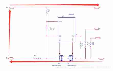
Encountered the method of recovery
because Q2 The existence of bulk diodes , You can plug in the charger , Charge the battery through the body diode , Restore to the cell 2.8V Then remove the protection of the protection board ,MOS The pipe is open , Form a complete circuit , Battery reaches 3.0V Back on .
4. Over current protection
Due to the chemical properties of lithium electronic batteries , Battery manufacturers have set upper limits for charging and discharging currents , When the upper limit is exceeded , It will cause permanent damage to the battery .
Take discharge as an example , When the battery is normally discharged , The discharge current will pass through the series connected MOS tube , because MOS The tube itself has a conduction impedance , A voltage is generated at both ends , The voltage value is U=2IRds,Rds For a single MOS The conduction impedance of the tube . control IC Your feet will be right VM The voltage value of the pin is constantly detected . If the load leads to excessive loop current for some reason , bring MOS When the conduction pressure drop of the pipe is greater than the specified value , Its “DO” The pin will be converted from high level to zero level , bring Q2 MOS Tube off , So as to cut off the circuit , Make the loop current 0, Play the role of overcurrent protection .
5. Short circuit protection
When the battery discharges the load , If the circuit current is large enough to make VM When the voltage value detected by the pin is greater than the specified value , control IC Then it is judged as load short circuit , Its “DO” The pin will quickly change from high level to zero level , bring Q2 MOS Tube changes from on to off , So as to cut off the discharge circuit , Play the role of short-circuit protection . The delay time of short-circuit protection is short , It is usually on the microsecond level . And the current value of short-circuit protection is much larger than that of overcurrent protection .
边栏推荐
- Mlperf training v2.0 list released, with the same GPU configuration, the performance of Baidu PaddlePaddle ranks first in the world
- Process communication mode between different hosts -- socket
- Arduino uses nrf24l01+ communication
- Altium designer learning (I)
- C language enhancement -- pointer
- The research found that the cross-border e-commerce customer service system has these five functions!
- Adaptive filter
- Use indent to format code
- Gradle composite construction
- Basic embedded concepts
猜你喜欢
【论文阅读】2022年最新迁移学习综述笔注(Transferability in Deep Learning: A Survey)
Hardware and software solution of FPGA key chattering elimination
![[trio basic tutorial 16 from introduction to proficiency] UDP communication test supplement](/img/54/78e4e10724b2762274b06debb10877.jpg)
[trio basic tutorial 16 from introduction to proficiency] UDP communication test supplement

L'étude a révélé que le système de service à la clientèle du commerce électronique transfrontalier a ces cinq fonctions!
Drive LED -- GPIO control
Several implementation schemes of anti reverse connection protection of positive and negative poles of power supply!
Train your dataset with yolov4
![Shape template matching based on Halcon learning [v] find_ cocoa_ packages_ max_ deformation. Hdev routine](/img/a1/d13b37955b044b6be5f1fd10263c5e.jpg)
Shape template matching based on Halcon learning [v] find_ cocoa_ packages_ max_ deformation. Hdev routine
Explain task scheduling based on Cortex-M3 in detail (Part 1)
Ble encryption details
随机推荐
Some errors in configuring the environment
Slist of linked list
找不到实时聊天软件?给你推荐电商企业都在用的!
STM32 tutorial triple ADC interleaved sampling
C#,数值计算(Numerical Recipes in C#),线性代数方程的求解,LU分解(LU Decomposition)源程序
Communication standard -- communication protocol
【论文阅读】2022年最新迁移学习综述笔注(Transferability in Deep Learning: A Survey)
Shape template matching based on Halcon learning [9] PM_ multiple_ dxf_ models. Hdev routine -- [read and write XLD from DXF file]
Detailed explanation of SQL server stored procedures
String judgment
LED display equipment records of the opening ceremony of the Beijing Winter Olympics
Factors affecting the quality of slip rings in production
研究發現,跨境電商客服系統都有這五點功能!
C WinForm [view status bar -- statusstrip] - Practice 2
Relationship between line voltage and phase voltage, line current and phase current
Bootloader implementation of PIC MCU
WiFi wpa_ Detailed description of supplicant hostpad interface
General makefile (I) single C language compilation template
Embedded composition and route
Sql Server的存储过程详解