当前位置:网站首页>The cradle of eternity
The cradle of eternity
2022-07-07 01:38:00 【acktomas】
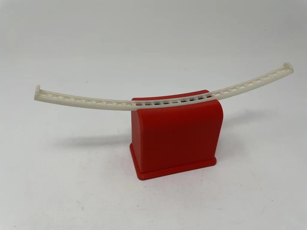
Marblevator, permanent ?, cradle
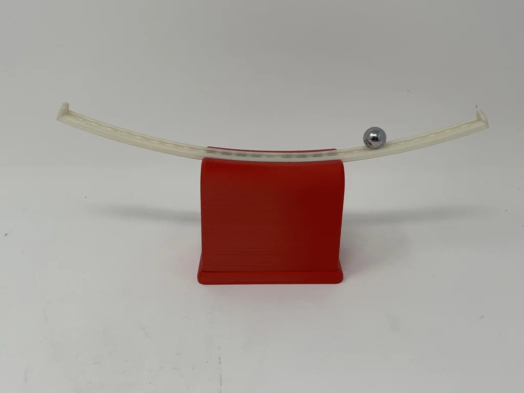
“Marblevator, Pertual?, Cradle”, for example “Marblevator, Perpetual?, Version 2” and “Marblevator, Perpetual?” It's not eternal at all , Because it's just another illusion . Like its predecessors , It is a very quiet illusion , The only noise is the sound of marble rolling back and forth in the cradle .
I added Arduino Nano 33 IoT.Nano The software uses two interrupt service programs activated by two infrared transceivers to control the illusion . When the ball bearing passes through the infrared transceiver , It will pass the Nano The input pin generates an interrupt , Thus, the interrupt service program associated with this pin is called . Each interrupt service program uses the interrupt history of two interrupt service programs to detect the downhill ball bearing movement . When downhill motion is detected , The software will send pulses to the solenoid , To accelerate the ball bearing to the other side of the track ( Because the model uses infrared transceiver to sense the ball bearing ,
I also include software that monitors battery voltage through resistive voltage dividers and analog input pins , When LiPo The battery voltage drops to the specified cut-off level (9.6vdc) Following time , send Nano put to sleep .
As usual , I may have forgotten oneortwo files , Or who knows what else , So if you have any questions , Please don't hesitate , Because I did make many mistakes .
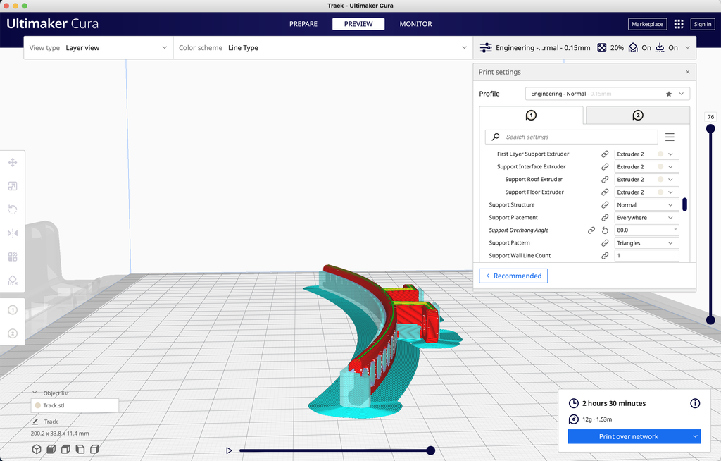
Use Autodesk Fusion 360 Design , Use Ultimaker Cura 4.12.1 Slice , And in Ultimaker S5 Upper use PLA Conduct 3D Print .
Last but not least , I will not design for use in this model 、 Parts and / Or materials to obtain any form of compensation .
Tools
- Soldering iron and solder .
- Red 、 black 、 Green and blue 28AWG One roll of stranded wire .
- Microgrid polishing sheet (1200、1500、2400、3200).
- sandpaper (120、220、400 and 600 Particle size ).
- Thick cyanoacrylate adhesive .
- Double sided tape .
- Velcro .
- Heat shrinkable tubes .
The first 1 Step : Spare parts .
I bought the following accessories :
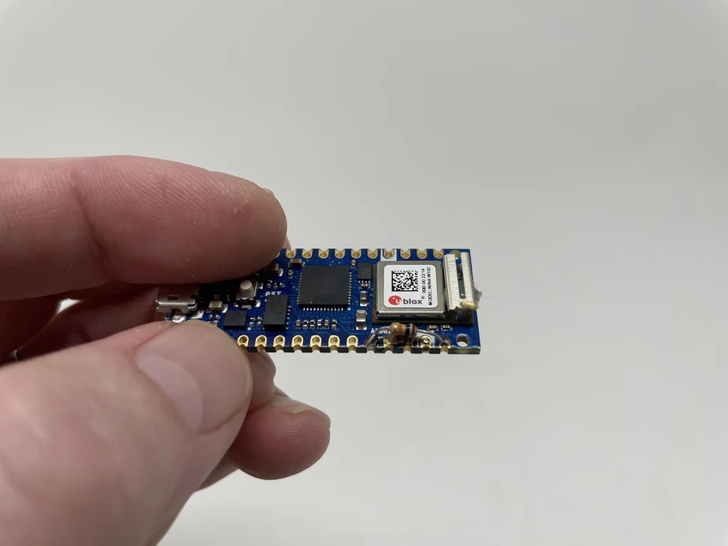
- One Arduino Nano 33 IoT [ABX00027]
- section 11.1vdc 300mAh 3S 30C The battery LiPo The battery .
- One for batteries JST Mating connector .
- One Gikfun EK1909“ Magnetic levitation coil ”.
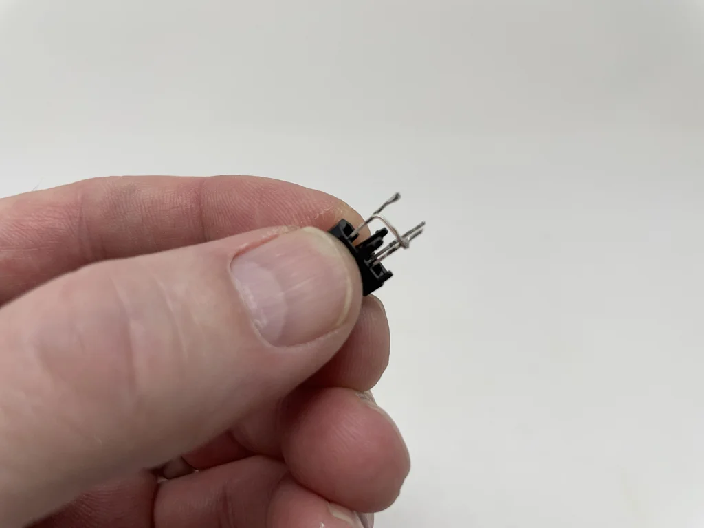
- Two TCRT5000 Infrared transceiver .
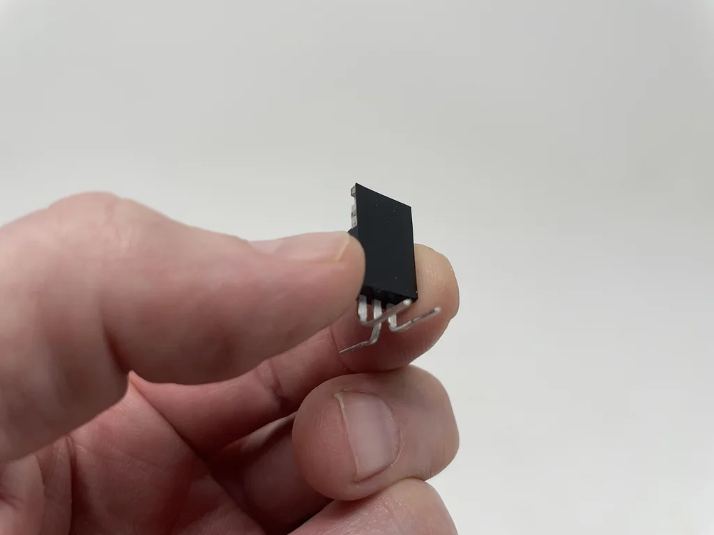
- One FQP30N06L MOSFET.
- One 1N4007 diode .
- One 10kΩ resistance .
- One 2.7kΩ resistance .
- Two 1KΩ resistance .
- One M3 x 8mm Countersunk screw .
- One 11MM Diameter ball bearing .
- One M3 x 8mm Countersunk screw .
I take 0.1 Mm floor height 、20% Filling quantity 3D The following parts were printed :
- One support PLA Of “Base.stl”.
- Two “ Bolt 、 install 、 coil .stl”.
- One “ Bottom .stl”.
- One “Mount, Coil.stl”.
- One with separation or PVA Supported by “Track.stl”( Need double extrusion 3D The printer , See above Cura Images ).
This is a precision printing and assembly model , Sometimes very small parts are used , Very narrow space . Before assembly , Test assembly and trim 、 File 、 Sand and all necessary parts , To make the moving surface move smoothly , And closely fit the non moving surface . According to your printer 、 Your printer settings and the color you choose , It may need more or less trimming 、 Archive or polish . Carefully document all edges that come into contact with the building board , To ensure that all building blocks “ Exudate ” Have been removed and all edges are smooth . I use small jewelers screwdriver And enough patience to perform this step . stay 3D Print Base.stl and Track.stl after , I carefully removed the support material with a flat screwdriver and pointed nose pliers .
The model also uses threaded components , therefore M8 x 1.25 Taps and dies will assist in thread cleaning when necessary .
The attachment
 Base.stl
 Bolt 、 install 、 Plate and coil .stl
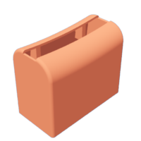
case.stl
install 、 Circuit board and coil .stl
orbital .stl
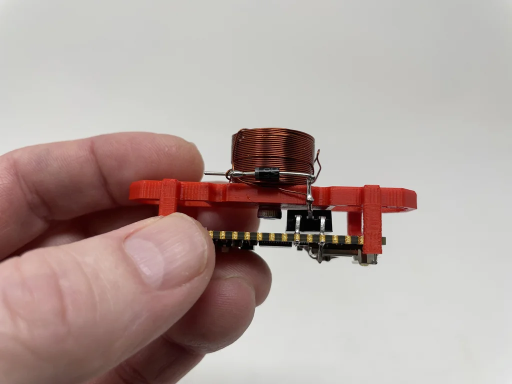
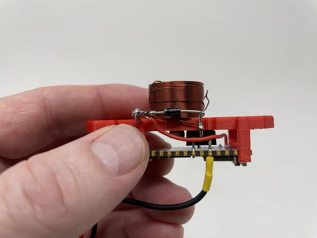
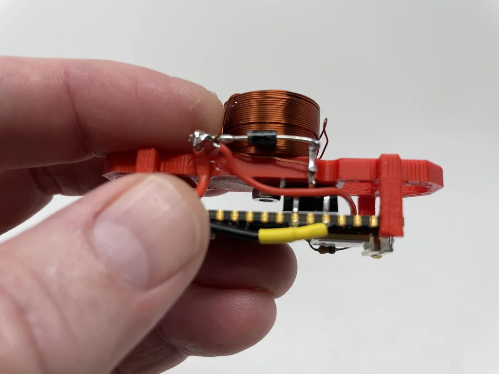
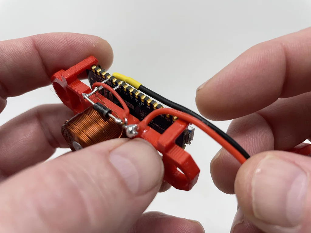
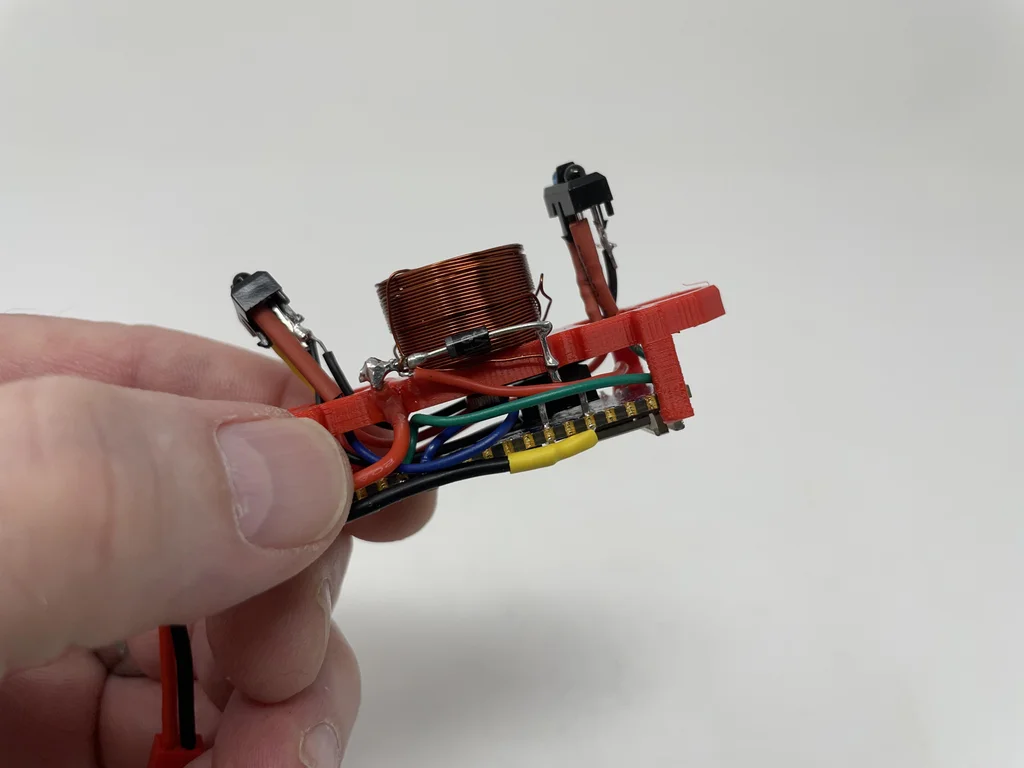
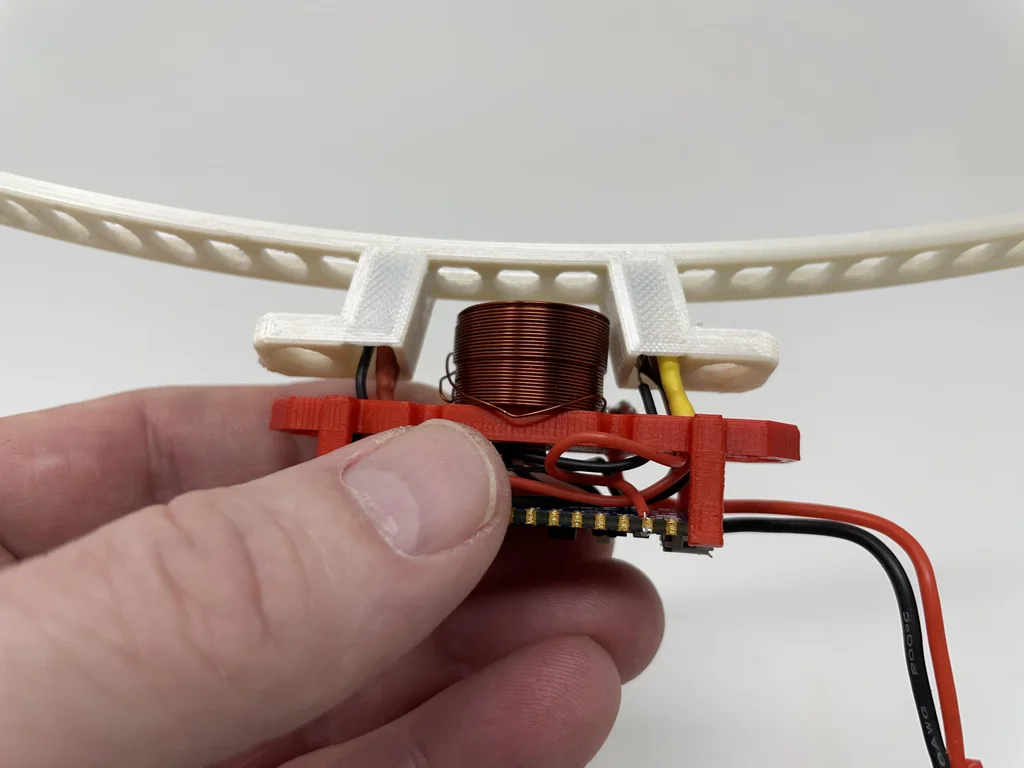
The first 2 Step : Circuit board and coil mounting assembly .
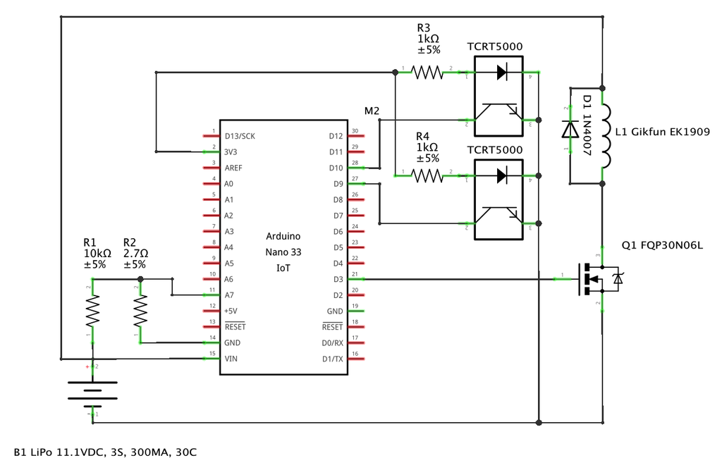
Refer to the attached electronic design schematic diagram of the model , I assemble the circuit board and coil support as follows :
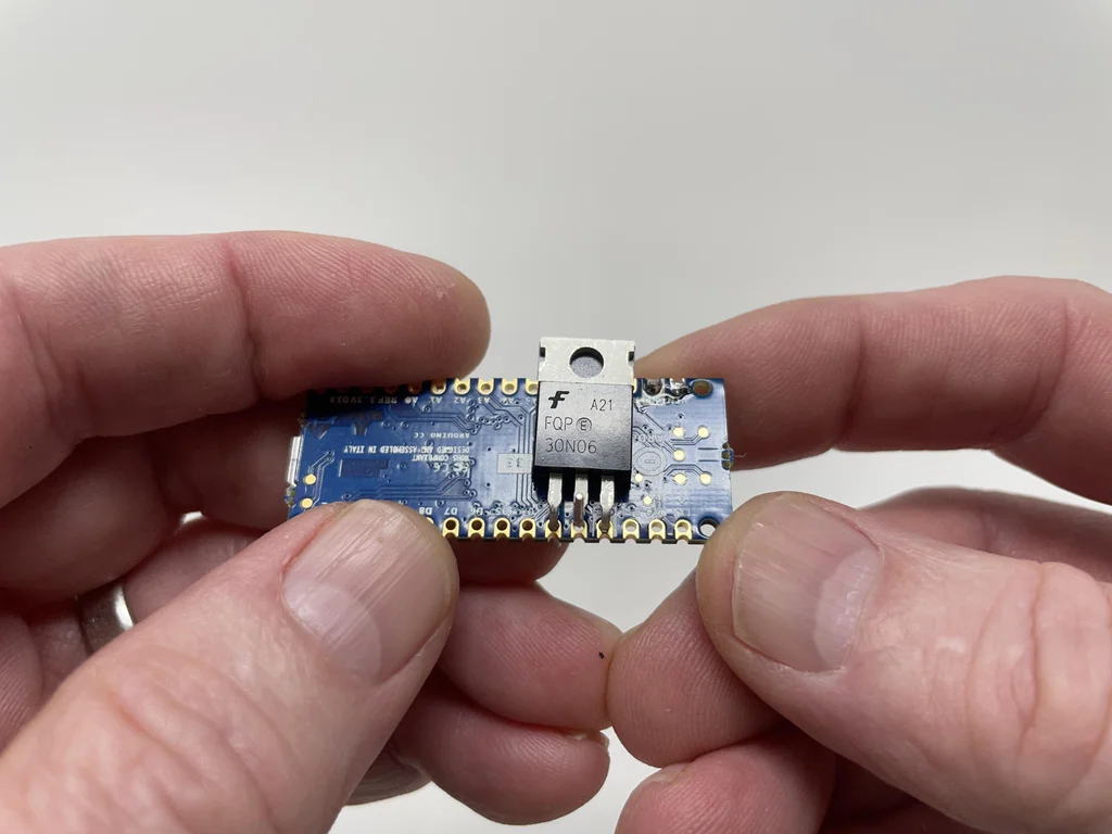
Bend down MOSFET Grid and source leads , Then bend the drain lead upward .
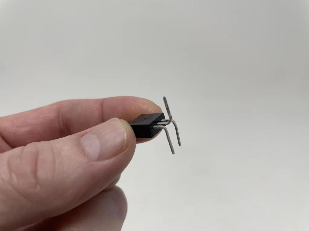
Insulate with electrical tape MOSFET The back of the heat sink .
stay Nano The pin of A7 and GND Insert between 2.7kΩ resistance .
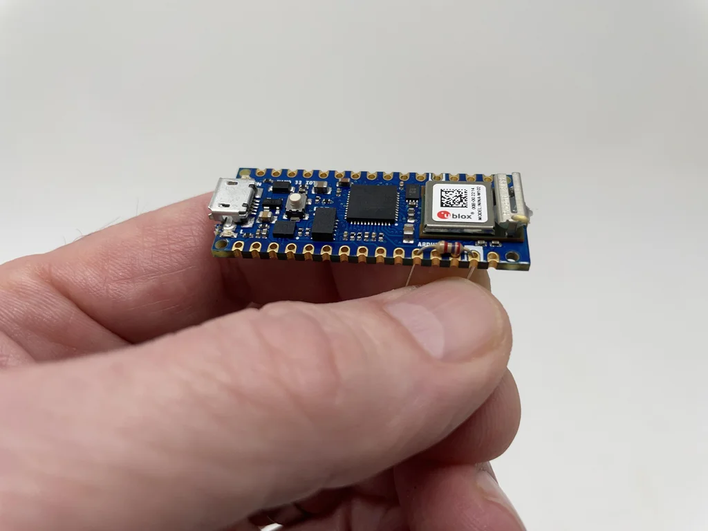
stay Nano The pin of A7 and Vin Between pins 2.7kΩ Insert on the resistor 10kΩ resistance .
Weld the first two inserted resistors to Nano And trim the lead .
Use countersunk screws to connect the coil to “Mount, Board and Coil.stl”.
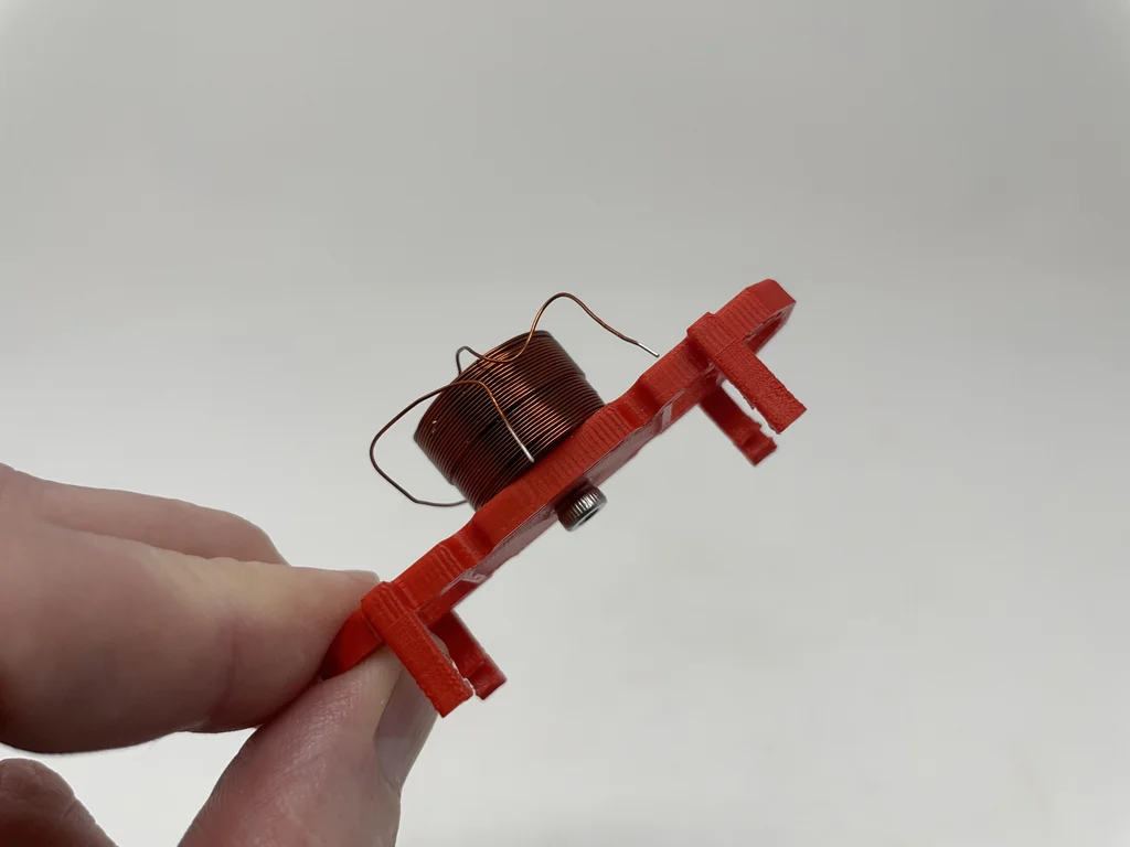
take MOSFET Insert from the bottom Nano, Gate pin to D3, Source pin to GND, Drain pin up .
take Nano Clip in the installation components .

take MOSFET Put in Nano Above the lower surface 3mm It's about , take MOSFET The grid and ground leads are welded to Nano, Then trim the grid leads , Leave the source leads for later welding .
Wrap the tip of an uninsulated coil wire around MOSFET Around the drain pin , Then weld it .
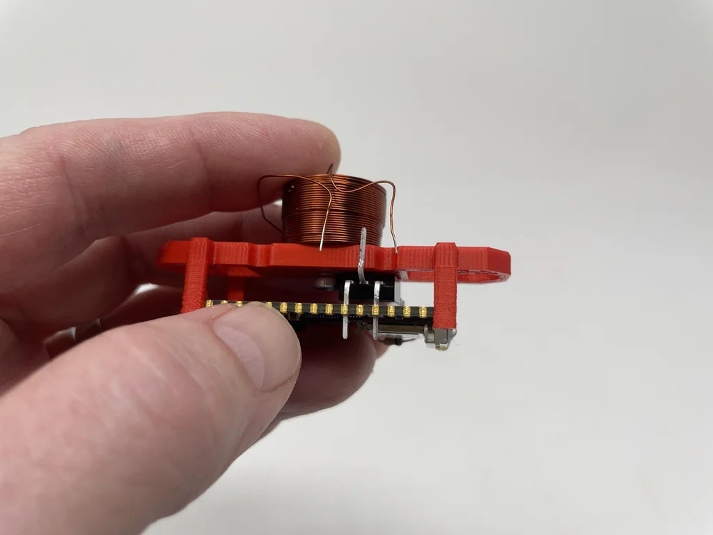
Wrap the anode lead of the diode around MOSFET Around the drain pin , Then weld it .
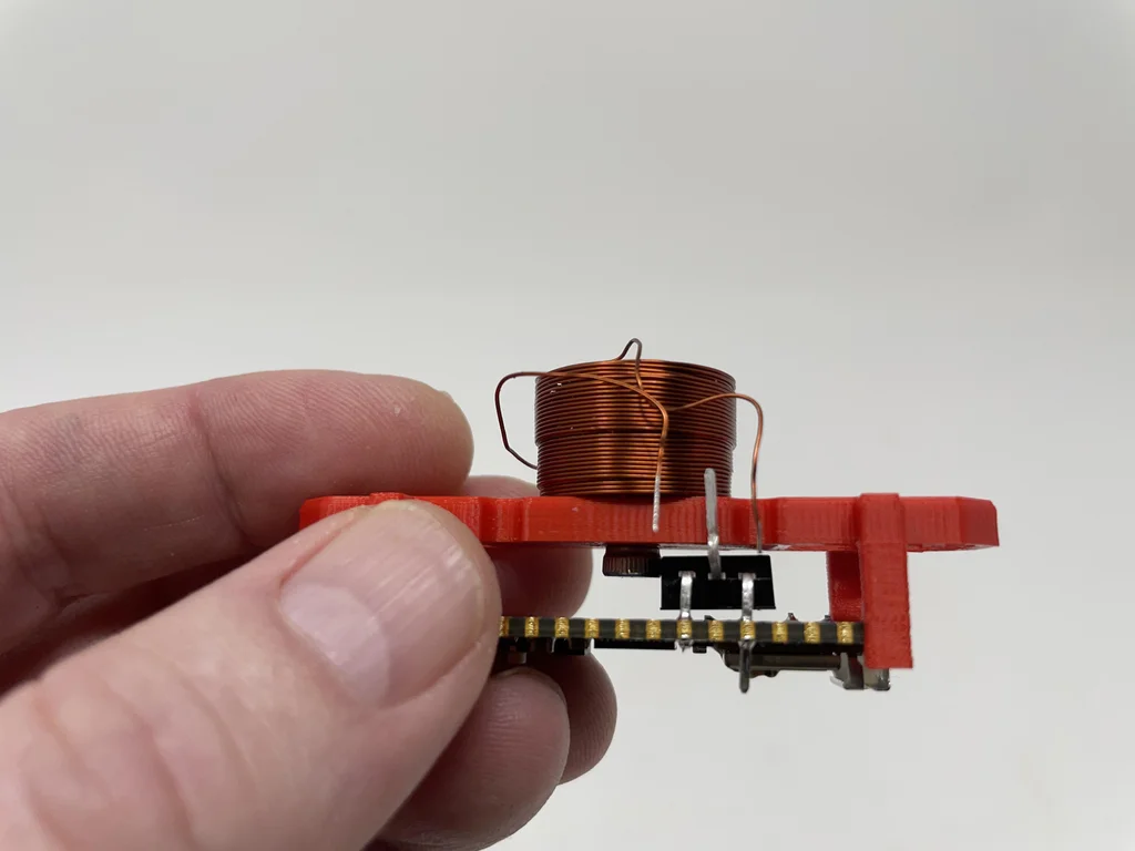
Wrap the tip of the remaining uninsulated coil wire around the cathode lead of the diode , Then weld it .
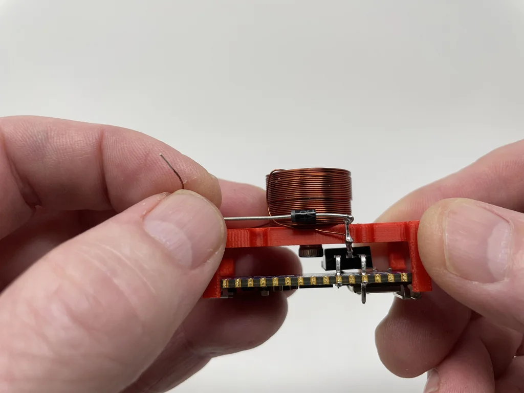
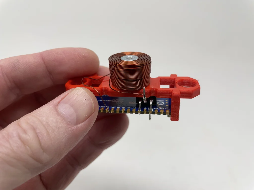
Slide the shrink tube onto JST Match the black line of the connector , Weld the black wire to MOSFET Source lead , Slide the shrink fit tube onto the welded joint , And apply enough heat to the heat shrinkable pipe to insulate the joint .
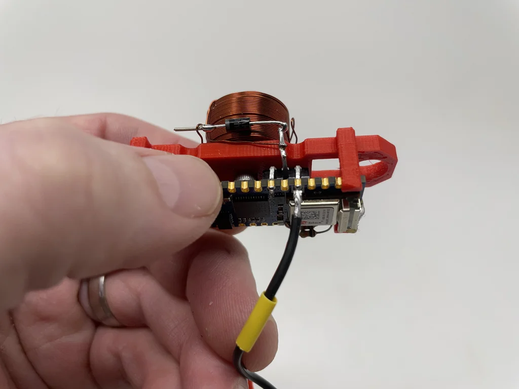
take JST The red wire of the paired connector is welded to the cathode lead of the diode .
take JST The red wire insulation glue of the mating connector is glued to the mounting base to eliminate the stress .
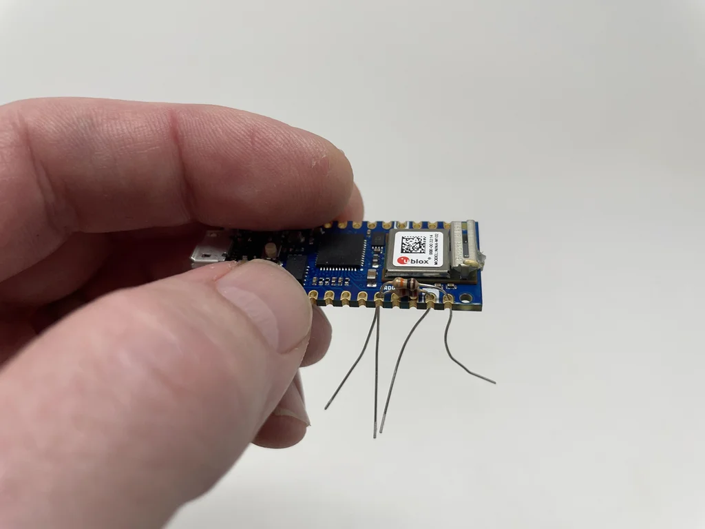
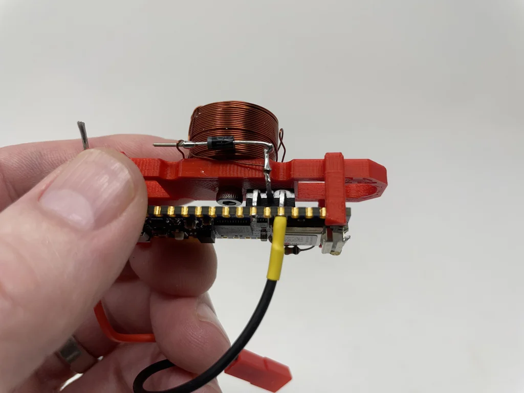
At the cathode of the diode and Nano Of VIN The pins are soldered 60 Mm long wire .
Be careful to MOSFET The insulated source wire is bent onto the board .
take JST The red and black wires of the mating connector are insulated and glued to the base to eliminate stress .
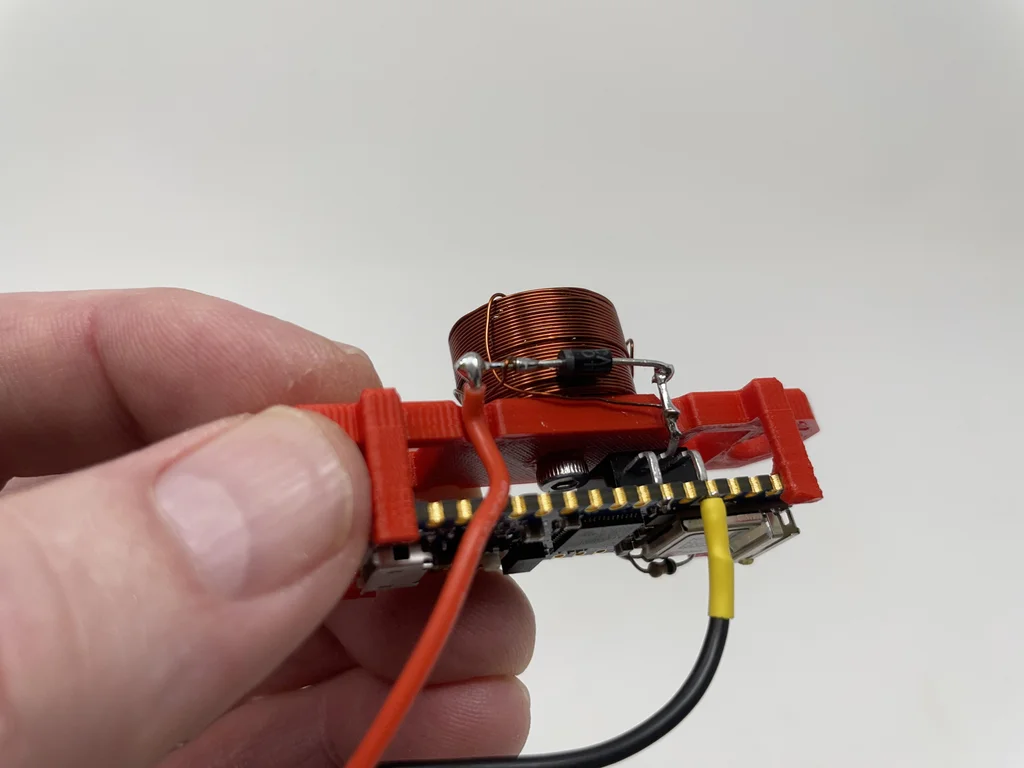
The first 3 Step : Infrared transceiver assembly .
Refer to the electronic design diagram of the model again , I assemble the infrared sensor as follows :
The first one. TCRT5000 The anode lead is bent to the first TCRT5000 Emitter leads , Weld the two leads together , Then trim all leads .
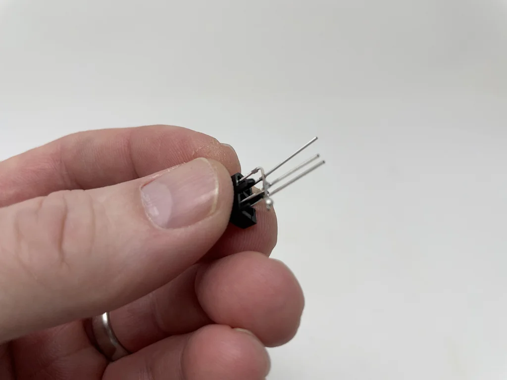
At the first TCRT5000 An anode lead is welded 1KΩ resistance .
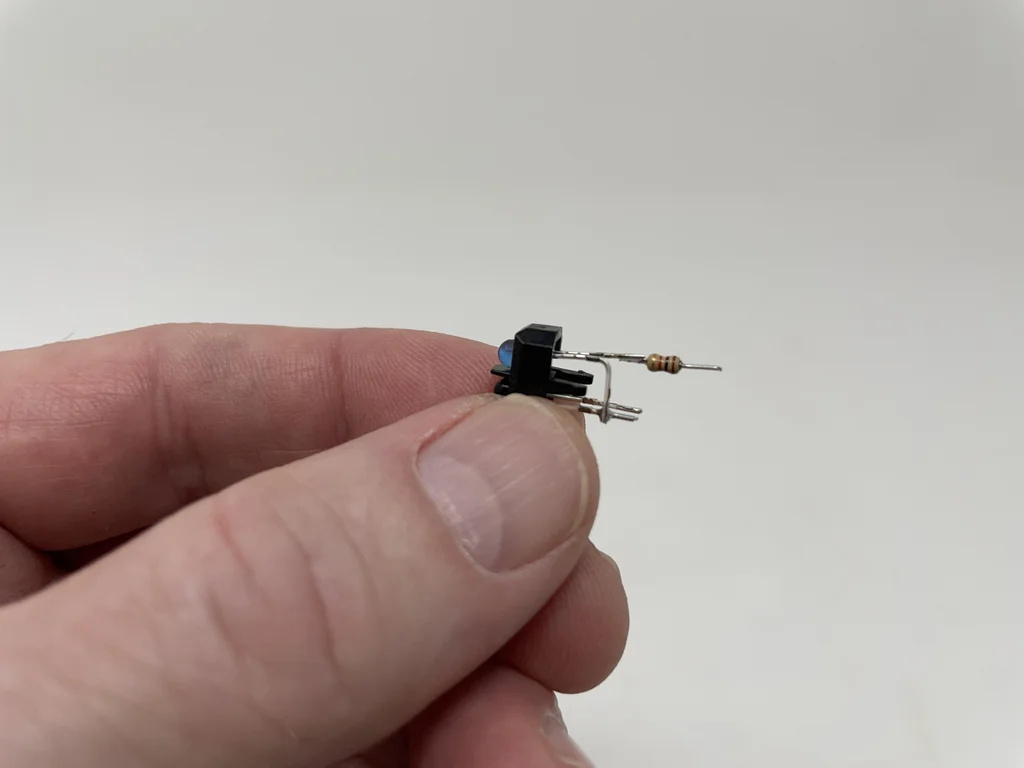
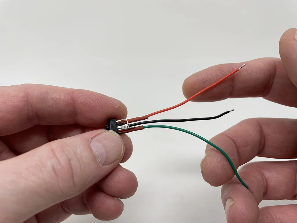
take 80mm The long red line is welded to 1KΩ The free end of the resistor , Then use a heat shrink tube to insulate the resistance solder joint .
take 80 Mm long black wire is welded to the first TCRT5000 Emitter leads .
take 80 Mm long green wire welded to the first TCRT5000 On the collector lead , Then use heat shrinkable tube to insulate the welding joint .

Put the second TCRT5000 The anode lead is bent to the second TCRT5000 Cathode lead , Weld the two leads together , Then trim all leads .
Will a 1KΩ Resistance welding to the second TCRT5000 Anode lead .
take 80 Mm long blue line welded to the second TCRT5000 On the collector lead , Then use heat shrinkable tube to insulate the welding joint .
The first one. TCRT5000 The components are placed near the installation components , Insert its wire into the first one in the installation assembly TCRT5000 hole , Then pass them up through the second of the installation components TCRT5000 hole .
take 80 Mm long black line and from the first TCRT5000 The black line of the assembly is welded to the second TCRT5000 Emitter leads .
take 80 Mm long red line and TCRT5000 The red lines in the assembly are welded together , take 20 Mm long heat shrinkable tube is sleeved on the wire , Weld these wires to the second TCRT5000 Resistance free end , Slide the shrink tube over the solder joint , Then heat it to shrink .
The first one. TCRT5000 The green line of is welded to Nano Pin D10.
Put the second TCRT5000 The blue line of is welded to Nano Pin D9.
Put the second TCRT5000 The black line of is welded to Nano GND Pin .
Put the second TCRT5000 The red line of is welded to Nano 3.3V Pin .
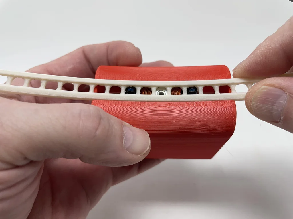
stay “Track.stl” On the use of 120 Grind the ball bearing guide rail with No. 1 sandpaper , And then use 220、400 and 600 Sanding with sandpaper , And then use Micromesh 1500、1800、2400 and 3200 The guide rail is finely polished .
Carefully place each TCRT5000 Transceiver socket sliding into the track .
Use two “Bolt, Mount, Board and Coil.stl” Connect the rail to the mounting assembly .

The first 4 Step : Software .
Arduino file “MarblevatorCradle.ino”, It will be downloaded to Nano Software in . The software is divided into four parts ;setup()、loop()、InterruptServiceInfraredTransceiver1() and InterruptServiceInfraredTransceiver2().
setup() The function contains initialization code . Disable after interrupt , The code will be used to drive mosfet The pins of are assigned as digital outputs and the outputs are cleared . Next, assign two infrared transceiver input pins and attach the corresponding interrupt . Last , The software will be built in LED Pin set to output , Then enable interrupts .
loop() The function contains the code needed to monitor the battery voltage . The lithium polymer battery I used in this model has no low-voltage cut-off protection , So I let Nano loop() Function assumes this responsibility . In a statement 、 After initializing and calculating various battery voltage parameters , There will be a ten second delay . After the delay , Get the battery voltage a/d Count and compare it with the cut-off of the calculation a/d Count for comparison . If the battery voltage is lower than the cut-off voltage ,Nano Will go to sleep .
Finally, there are two interrupt service programs ,InterruptServiceInfraredTransceiver1() and InterruptServiceInfraredTransceiver2(), Each is associated with an infrared transceiver . When the ball bearing rolls on the infrared transceiver , The infrared transceiver collector output will become low , Thus, the interrupt service program of the infrared transceiver is called . After the delay , The interrupt service program waits for the rising edge of the interrupt pin , Then determine whether to pulse the coil . Now the global variable bLastInfraredTransceiverSensorInterrupt Will become one of three values ;0、1 or 2. If 0, Indicates that there was no interruption before , It indicates that the model has just been powered on , So the coil will send a pulse . If 1 And the current interrupt service program is 1, Or if 2 And the current interrupt service program is 2, Then the interrupt service program is the interrupt service program when the last bearing rolls uphill . The second consecutive interruption in the same interruption service program indicates that the ball bearing is rolling downhill , Therefore, the coil will generate pulses . Whether or not the coil has pulses , Software will be in bLastInfraredTransceiverSensorInterrupt Record the interrupt service sensor number , Prepare for the next interruption .
The attachment
MarblevatorCradle.ino
Step five : Ball bearing stroke adjustment .
The software includes settings to 1600 Microsecond (1.6 millisecond ) The constant COIL_ON_MICROSECONDS. According to the grinding and polishing degree of the ball bearing guide , If the ball bearing moves too far ( For example, it collides with the rail end cover ), You may need to reduce this value , If the ball bearing does not move far enough , You may need to increase the value . I perform the following steps to adjust COIL_ON_MICROSECONDS Value :
- Place the rail and mounting assembly in a small vice and check the levelness , If not level , I level it .
- take Nano Connected to my computer USB port , Download software to Nano, Then disconnect USB cable .
- Connect the battery to the assembly JST The connector .
- Place the ball bearing on one end of the rail and loosen .
- Monitor the movement of the ball bearings .
- If you need to adjust the stroke , I unplug the battery , take USB Connect the cable to Nano, take
COIL_ON_MICROSECONDSFrom 100 Change to 150, Download changes to Nano, To break off USB cable , Reconnect the battery , Then repeat as needed .
If COIL_ON_MICROSECONDS The value of becomes too large ( exceed 3.0 ms 3000 Microsecond ), I will polish the track again , Because the coil may become hot enough to twist the mounting components and / Or track . I measured the prototype at about 2 Fahrenheit ( Therefore, the coil temperature is 74 Fahrenheit ) The average coil temperature rise exceeds the ambient room temperature (72 degree ).
The pulse width of the coil is 1.6ms, The ball bearing in the prototype model rolls from end cap to end cap , The maximum current consumption is 112mAh( During the coil pulse ), The minimum current consumption is 10mAh( Place the front ball bearing ), The average current consumption is 25mAh( function 30 Minutes later ).
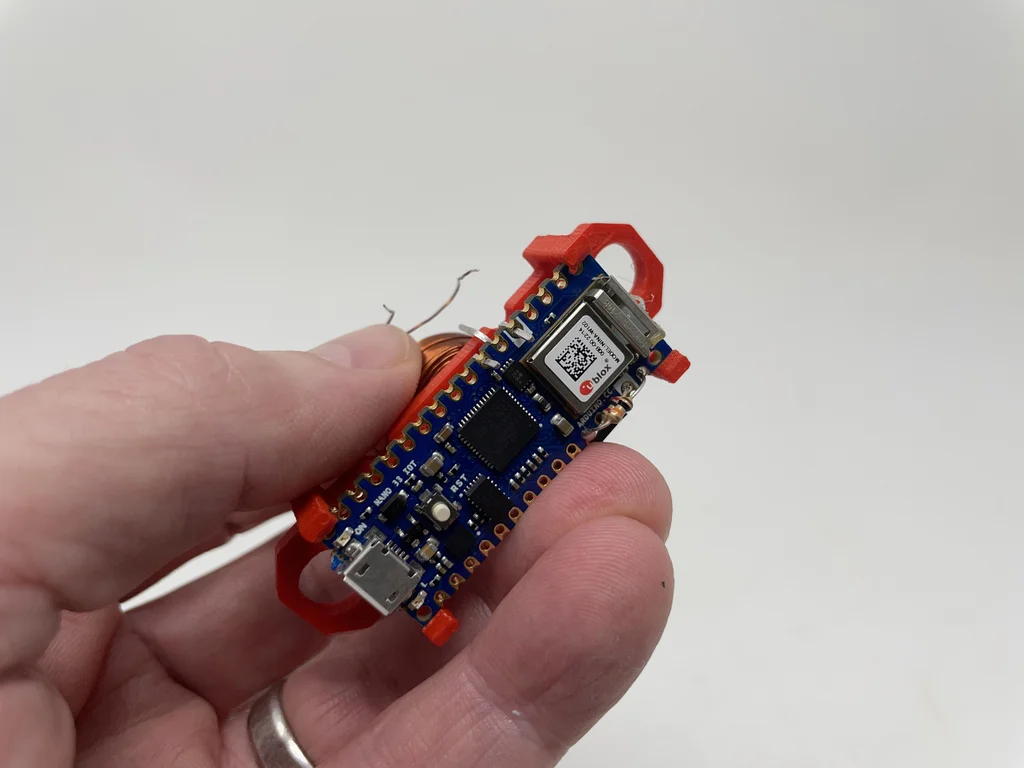
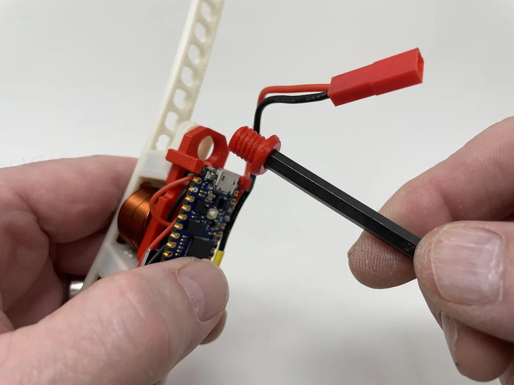
The first 6 Step : General assembly .
For final assembly , After the ball bearing stroke is adjusted . I performed the following steps :
Unplug the battery .
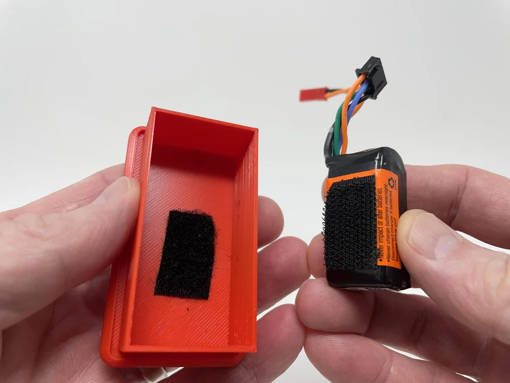
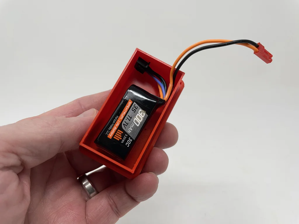
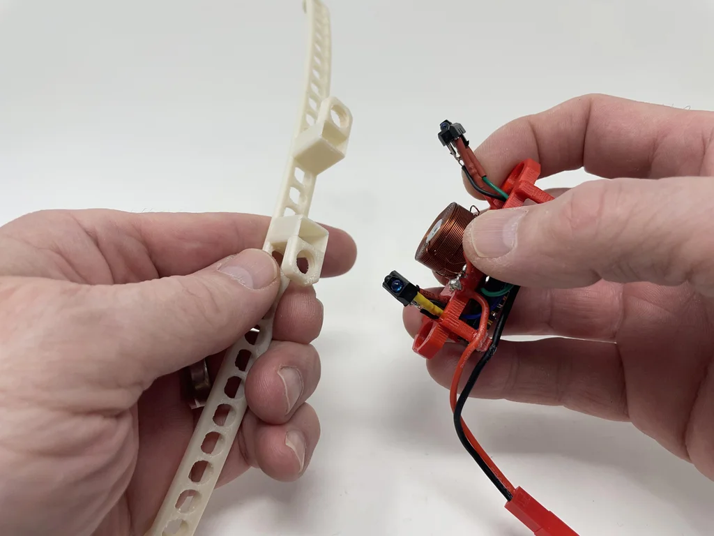
Use Velcro Connect the battery to “Base.stl”.
Remove the bolts that secure the rail to the mounting assembly .
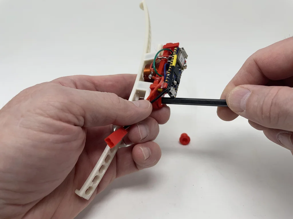
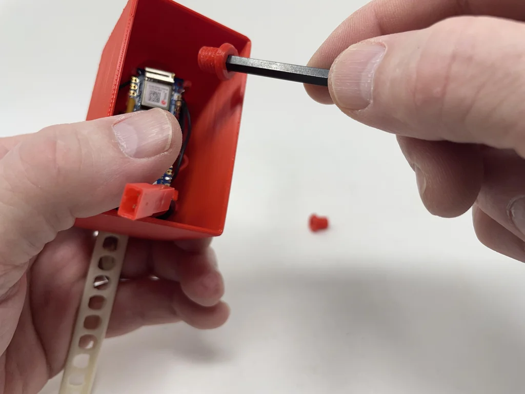
Carefully remove from the rail socket TCRT5000 Components .
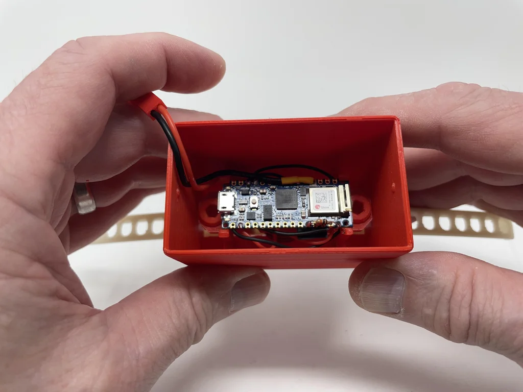
Put the installation components into “Case.stl” in , send TCRT5000 The component exits the track slot on the top of the chassis .
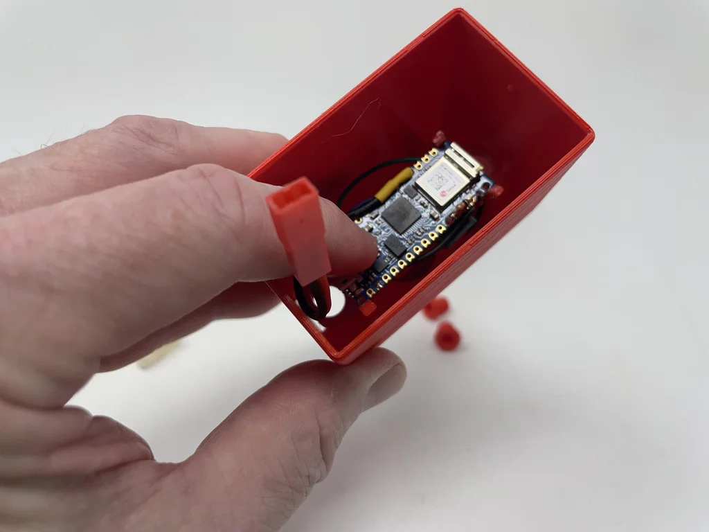
Be careful to TCRT5000 Insert the assembly completely into the rail socket .
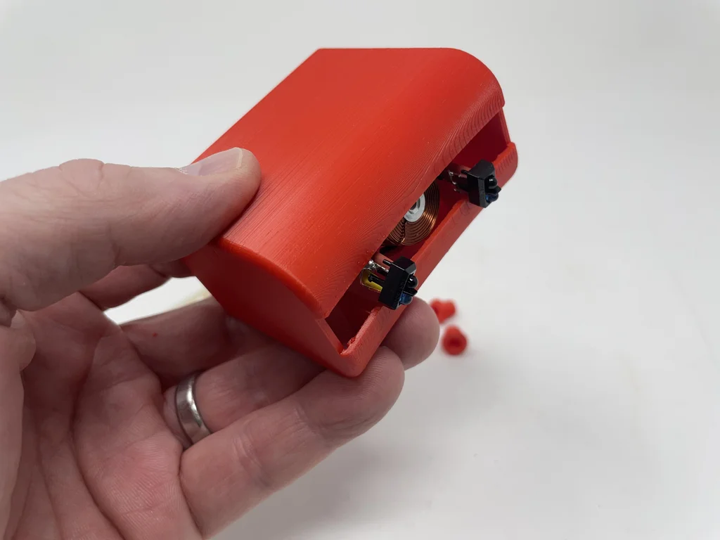
Fix the rail to the mounting assembly and housing with two bolts .
Plug in the battery .
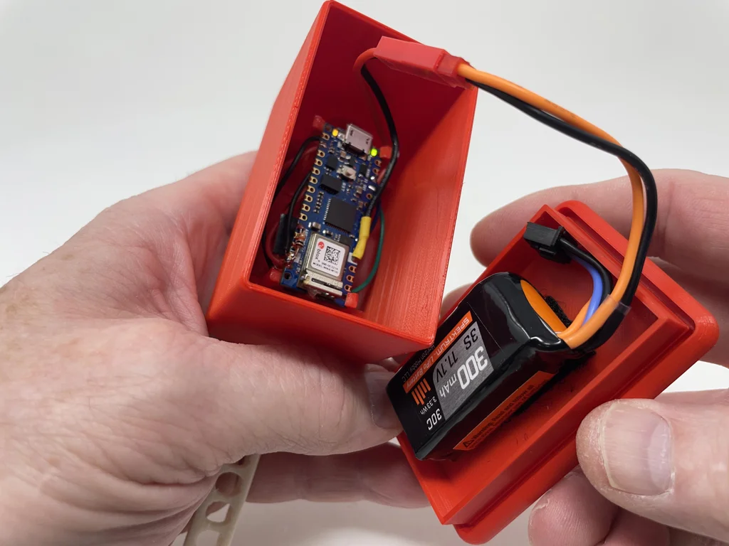
Press the base assembly into the housing assembly .
Loosen the ball bearing from one end of the rail .
I am what I am 3D Print 、 welding 、 Adjustment and assembly “Marblevator, Perpetual?, Cradle” The way .
边栏推荐
- 鼠标右键 自定义
- 2022 Google CTF SEGFAULT LABYRINTH wp
- 前置机是什么意思?主要作用是什么?与堡垒机有什么区别?
- 【信号与系统】
- Machine learning: the difference between random gradient descent (SGD) and gradient descent (GD) and code implementation.
- 长按按钮执行函数
- 字节P7专业级讲解:接口测试常用工具及测试方法,福利文
- How to manage distributed teams?
- Neon Optimization: performance optimization FAQ QA
- 糊涂工具类(hutool)post请求设置body参数为json数据
猜你喜欢
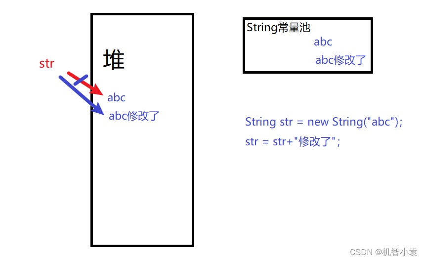
Today's question -2022/7/4 modify string reference type variables in lambda body
AI automatically generates annotation documents from code
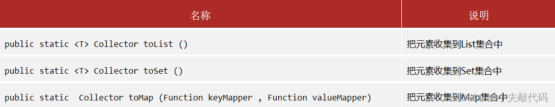
黑马笔记---创建不可变集合与Stream流
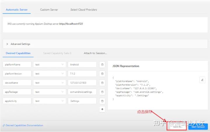
Appium foundation - appium inspector positioning tool (I)
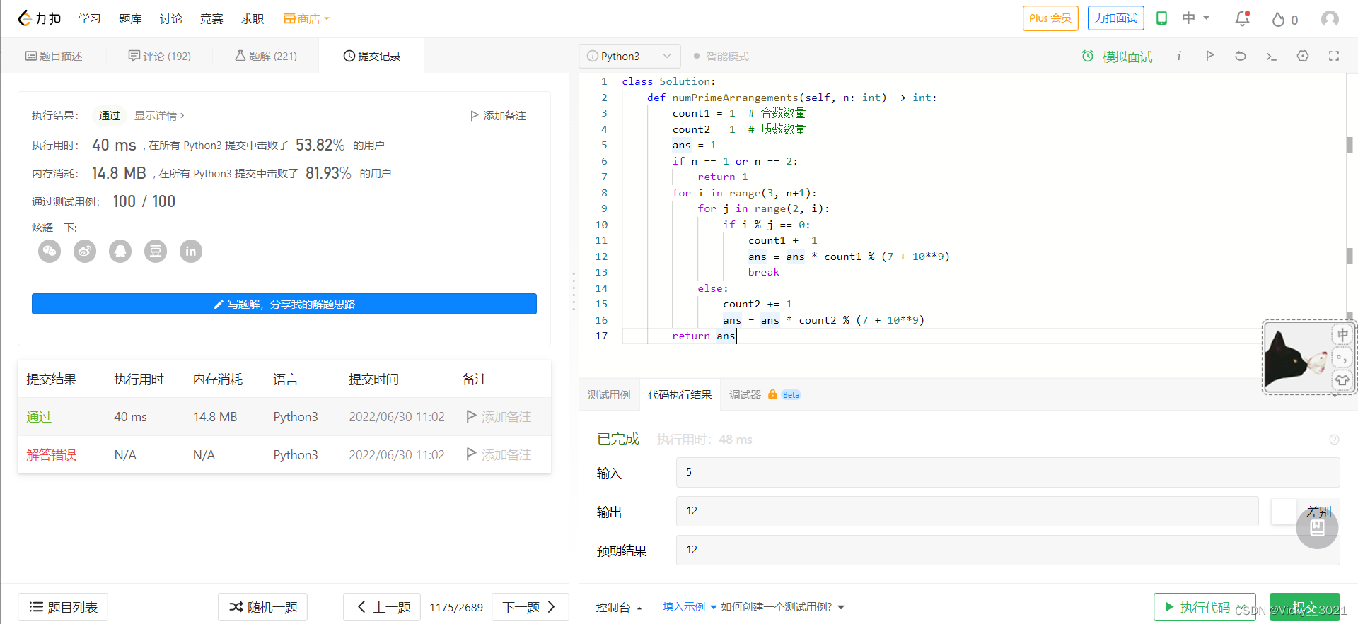
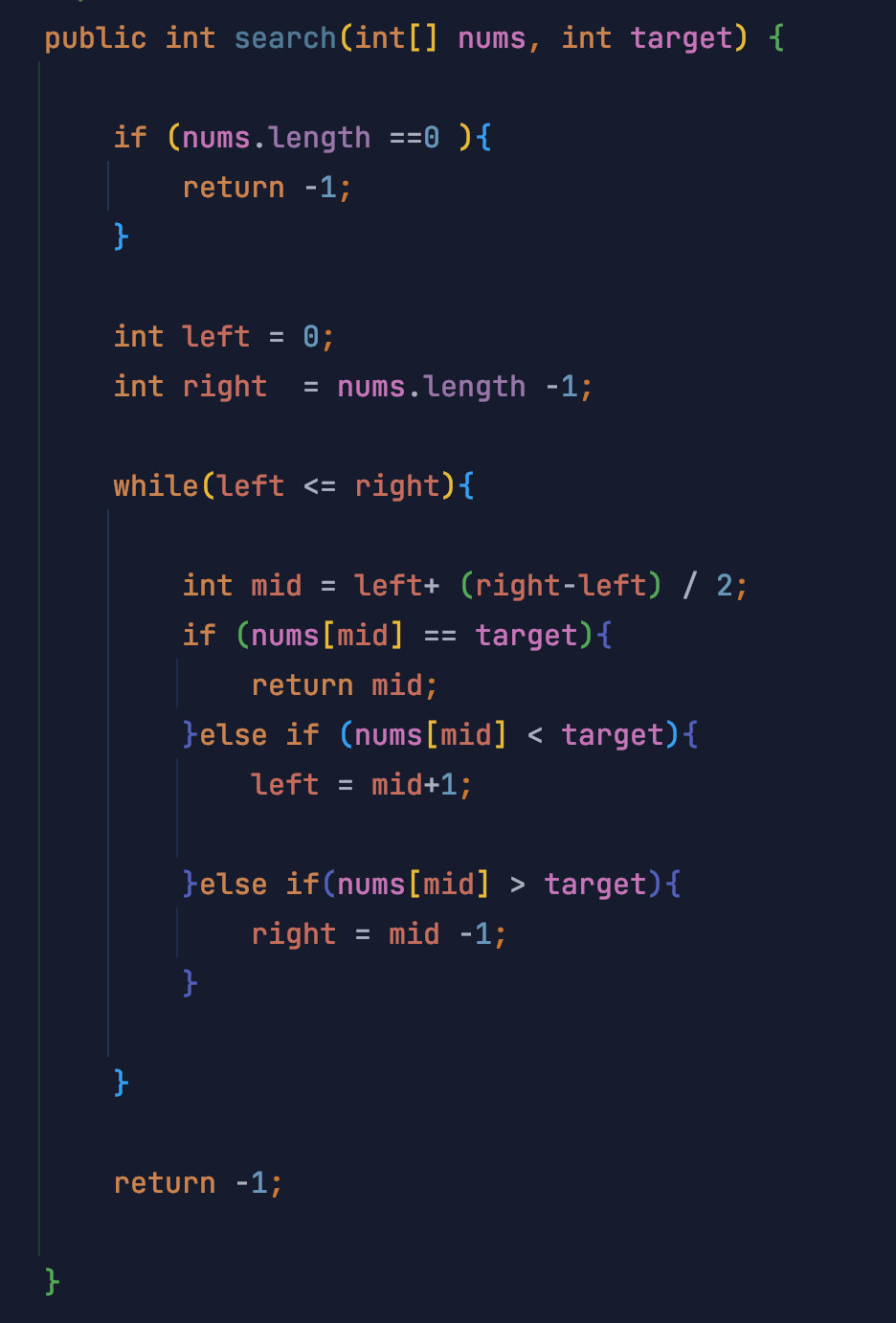
LeetCode:1175. 质数排列
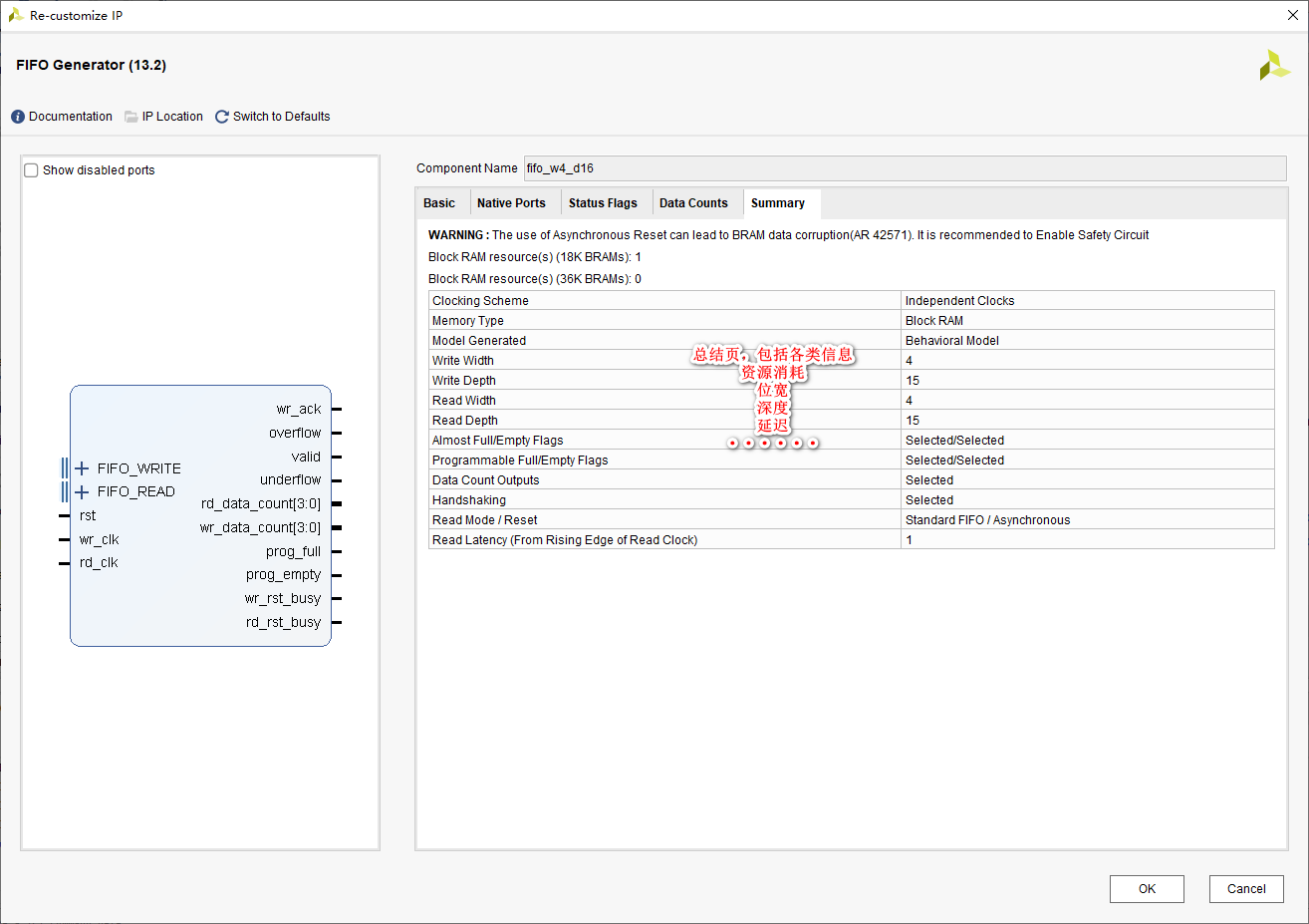
Start from the bottom structure to learn the customization and testing of fpga---- FIFO IP

Yunna - work order management system and process, work order management specification

Comparison of picture beds of free white whoring
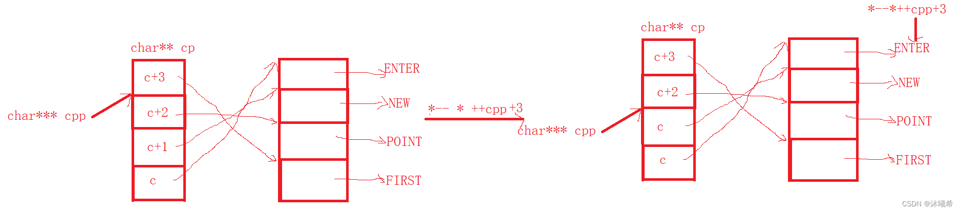
【C语言进阶篇】指针的8道笔试题
Gazebo的安装&与ROS的连接
随机推荐
2022 Google CTF SEGFAULT LABYRINTH wp
js如何快速创建一个长度为 n 的数组
编译命令行终端 swift
dvajs的基础介绍及使用
C language instance_ five
交叉验证如何防止过拟合
2022 Google CTF SEGFAULT LABYRINTH wp
Wood extraction in Halcon
C语言实例_3
从底层结构开始学习FPGA----FIFO IP的定制与测试
AI 从代码中自动生成注释文档
LeetCode:1175. Prime permutation
WCF基金会
JS ES5也可以创建常量?
Metauniverse urban legend 02: metaphor of the number one player
AcWing 1141. 局域网 题解(kruskalkruskal 求最小生成树)
云呐-工单管理制度及流程,工单管理规范
对C语言数组的再认识
分享一个通用的so动态库的编译方法
图片打水印 缩放 和一个输入流的转换