当前位置:网站首页>Learning record: use STM32 external input interrupt
Learning record: use STM32 external input interrupt
2022-07-06 15:33:00 【Bitter tea seeds】
List of articles
Learning notes : The concept of external input interrupt , And the configuration method ;
List of articles
Preface
STM32F1 Each IO Can be used as an interrupt input port for external interrupts .STM32F103 The interrupt controller supports 20 External interrupts / Event request .
Each interrupt is provided with a status bit , Every interrupt / Events have independent trigger and mask settings .
STM32F103 Of 20 An external interrupt is :
EXTI Line 0~15: Corresponding to the outside IO The input of the port is interrupted .
EXTI Line 16: Connect to PVD Output .
EXTI Line 17: Connect to RTC Alarm clock event .
EXTI Line 18: Connect to USB Wake Events .
EXTI Line 19: Wake up event connected to Ethernet .
One 、EXTI brief introduction
EXTI(External interrupt/event controller)— External interrupt / Event controller , Managed the controller's 20 A break / Event line . Every interrupt / Each event line has an edge detector , It can detect the rising edge and falling edge of the input signal .EXTI It can be implemented for each interrupt / Event lines are configured separately , It can be configured separately as interrupt or event , And the properties that trigger the event .
Two 、EXTI Functional block diagram
( Learn from the wildfire reference manual )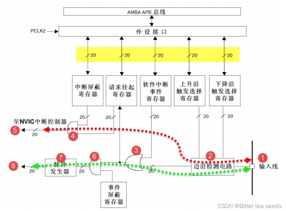
EXTI It can be divided into two major functions , One is to generate interrupts , The other is the generation of events , These two functions are different in hardware .
2.1、 Red reference line
Number 1 It's the input line ,EXTI The controller has 19 A break / Event input line , These input lines can be set to any one through the register GPIO, It can also be peripheral events , The input line is generally a signal with level change .
Number 2 It's an edge detection circuit , It triggers the selection register based on the rising edge (EXTI_RTSR) And falling edge trigger select register (EXTI_FTSR) The setting of the corresponding bit controls the signal triggering . The edge detection circuit takes the input line as the signal input terminal , If edge jump is detected, an effective signal is output 1 Number 3 circuit , Otherwise, invalid signal will be output 0. and EXTI_RTSR and EXTI_FTSR Two registers can be used to determine which type of level jump the controller needs to detect , It can be triggered only by the rising edge 、 Only the falling edge triggers or both the rising edge and the falling edge trigger .
Number 3 The circuit is actually a Or gate circuit , It's an input from the number 2 circuit , The other input comes from the software interrupt event register (EXTI_SWIER).EXTI_SWIER Allows us to start interrupts through program control / Event line , So either of these two inputs has a valid signal 1 You can output 1 Number 4 And number 6 circuit .
Number 4 The circuit is a AND gate , One of its inputs is the number 3 circuit , The other input is from the interrupt mask register (EXTI_IMR). And gate circuit requires both inputs to be 1 Just output 1, The result is if EXTI_IMR Set to 0 when , No matter the number 3 The output signal of the circuit is 1 still 0, Final number 4 The output signal of the circuit is 0; If EXTI_IMR Set to 1 when , Final number 4 The output signal of the circuit is numbered by 3 The output signal of the circuit determines , This can be easily controlled EXTI_IMR To achieve the purpose of whether to generate an interrupt . Number 4 The output signal of the circuit is stored in the suspend register (EXTI_PR) Inside , If you are sure of the number 4 The circuit output is 1 It will EXTI_PR Corresponding position 1.
Number 5 Yes, it will EXTI_PR The contents of the register are output to NVIC Inside , So as to realize system interrupt event control .
2.2、 Green reference line
The event line is numbered 3 After the circuit and interrupt the line is different , Before, the circuits were all shared .
Number 6 The circuit is a And gate , It's an input from the number 3 circuit , The other input comes from the event mask register (EXTI_EMR). If EXTI_EMR Set to 0 when , No matter the number 3 The output signal of the circuit is 1 still 0, Final number 6 The output signal of the circuit is 0; If EXTI_EMR Set to 1 when , Final number 6 The output signal of the circuit is numbered by 3 The output signal of the circuit determines , So we can simply control EXTI_EMR To achieve the purpose of whether an event occurs .
Number 7 It's a Pulse generator circuit , When its input , I.e. number 6 The output of the circuit , It's a valid signal 1 A pulse will be generated ; If the input is invalid, the pulse will not be output .
Number 8 It's a pulse signal , Is the final product of the line that produces the event , This pulse signal can be used by other peripheral circuits , Like timers TIM、 Analog to digital converter ADC wait , Such pulse signals are generally used to trigger TIM perhaps ADC Start conversion .
The purpose of generating the interrupt line is to input the input signal to NVIC, The next step is to run the interrupt service function , Realization function , This is software level . The purpose of the event line is to transmit a pulse signal to other peripherals , And it's circuit level signal transmission , At the hardware level .
EXTI Is in APB2 On the bus
3、 ... and 、 interrupt / Event line
EXTI0 to EXTI15 be used for GPIO, Any one of them can be realized by programming control GPIO As EXTI The input source .EXTI0 Can pass AFIO External interrupt configuration register for 1(AFIO_EXTICR1) Of EXTI0[3:0] Bit selection is configured as PA0、PB0、PC0、PD0、PE0、PF0、PG0、PH0 perhaps PI0.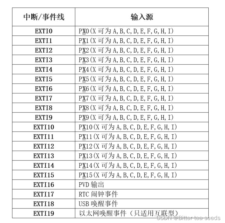
GPIO The pin of GPIOx.0~GPIOx.15(x=A,B,C,D,E,F,G,H,I) Corresponding to the interrupt line respectively 0~15.
In this way, each interrupt line corresponds to the maximum 9 individual IO mouth , By line 0 For example : It corresponds to GPIOA.0、GPIOB.0、GPIOC.0、GPIOD.0、GPIOE.0、GPIOF.0、GPIOG.0. The broken wire can only be connected to 1 individual IO On the mouth , In this way, it is necessary to determine which interrupt line to configure through configuration GPIO Yes .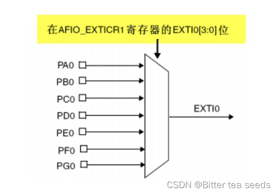
Four 、 General configuration steps for external interrupts
① initialization IO The mouth is the input .
GPIO_Init();
② Turn on IO Port multiplex clock .
RCC_APB2PeriphClockCmd(RCC_APB2Periph_AFIO,ENABLE);
③ Set up IO Mapping relationship between port and interrupt line .
void GPIO_EXTILineConfig();
④ Initialize online interrupt , Set trigger conditions, etc .
EXTI_Init();
⑤ Configure interrupt grouping (NVIC), And can interrupt .
NVIC_Init();
⑥ Write interrupt service function .
EXTIx_IRQHandler();
⑦ Clears the interrupt flag bit
EXTI_ClearITPendingBit();
5、 ... and 、 Follow the external interrupt configuration steps , Code
exti.h The code is as follows
#ifndef __EXTI_H
#define __EXIT_H
#include "sys.h"

void EXTIX_Init(void);// External interrupt initialization

#endif
exti.c The code is as follows
#include "exti.h"
#include "led.h"
#include "key.h"
#include "delay.h"
#include "usart.h"
#include "beep.h"

/* External interrupt 0 Service program */
void EXTIX_Init(void)
{


			EXTI_InitTypeDef EXTI_InitStructure;
			NVIC_InitTypeDef NVIC_InitStructure;

			KEY_Init();	 //  Key port initialization

			RCC_APB2PeriphClockCmd(RCC_APB2Periph_AFIO,ENABLE);	// Enable multiplexing function clock

			//GPIOE.3  Interrupt line and interrupt initialization configuration   Falling edge trigger  //KEY1
			GPIO_EXTILineConfig(GPIO_PortSourceGPIOE,GPIO_PinSource3);
			EXTI_InitStructure.EXTI_Line=EXTI_Line3;// Specify the breakline to configure 3
			EXTI_InitStructure.EXTI_Mode = EXTI_Mode_Interrupt;	// Pattern : interrupt
			EXTI_InitStructure.EXTI_Trigger = EXTI_Trigger_Falling;// Trigger mode falling edge
			EXTI_Init(&EXTI_InitStructure);	  	// according to EXTI_InitStruct The parameter specified in EXTI register

			//GPIOE.4  Interrupt line and interrupt initialization configuration   Falling edge trigger  //KEY0
			GPIO_EXTILineConfig(GPIO_PortSourceGPIOE,GPIO_PinSource4);
			EXTI_InitStructure.EXTI_Line=EXTI_Line4;
			EXTI_Init(&EXTI_InitStructure);	  	// according to EXTI_InitStruct The parameter specified in EXTI register


			//GPIOA.0  Interrupt line and interrupt initialization configuration   Rising edge trigger  PA0 WK_UP
			GPIO_EXTILineConfig(GPIO_PortSourceGPIOA,GPIO_PinSource0);

			EXTI_InitStructure.EXTI_Line=EXTI_Line0;
			EXTI_InitStructure.EXTI_Trigger = EXTI_Trigger_Rising;
			EXTI_Init(&EXTI_InitStructure);		// according to EXTI_InitStruct The parameter specified in EXTI register


			NVIC_InitStructure.NVIC_IRQChannel = EXTI0_IRQn;			// Enable key WK_UP External interrupt channel
			NVIC_InitStructure.NVIC_IRQChannelPreemptionPriority = 0x02;	// preemption 2,
			NVIC_InitStructure.NVIC_IRQChannelSubPriority = 0x03;					// Sub priority 3
			NVIC_InitStructure.NVIC_IRQChannelCmd = ENABLE;								// Enable external interrupt channels
			NVIC_Init(&NVIC_InitStructure);

			NVIC_InitStructure.NVIC_IRQChannel = EXTI3_IRQn;			// Enable key KEY1 External interrupt channel
			NVIC_InitStructure.NVIC_IRQChannelPreemptionPriority = 0x02;	// preemption 2
			NVIC_InitStructure.NVIC_IRQChannelSubPriority = 0x01;					// Sub priority 1
			NVIC_InitStructure.NVIC_IRQChannelCmd = ENABLE;								// Enable external interrupt channels
			NVIC_Init(&NVIC_InitStructure);  	  // according to NVIC_InitStruct The parameter specified in NVIC register

			NVIC_InitStructure.NVIC_IRQChannel = EXTI4_IRQn;			// Enable key KEY0 External interrupt channel
			NVIC_InitStructure.NVIC_IRQChannelPreemptionPriority = 0x02;	// preemption 2
			NVIC_InitStructure.NVIC_IRQChannelSubPriority = 0x00;					// Sub priority 0
			NVIC_InitStructure.NVIC_IRQChannelCmd = ENABLE;								// Enable external interrupt channels
			NVIC_Init(&NVIC_InitStructure);  	  // according to NVIC_InitStruct The parameter specified in NVIC register

}
// External interrupt 0 Service program
void EXTI0_IRQHandler(void)
{

		delay_ms(10);// Desquamation
		if(WK_UP==1)	 	 //WK_UP Key
		{

				BEEP=!BEEP;
		}
		EXTI_ClearITPendingBit(EXTI_Line0); // eliminate LINE0 Interrupt flag bit on
}


// External interrupt 3 Service program
void EXTI3_IRQHandler(void)
{

		delay_ms(10);// Desquamation
		if(KEY1==0)	 // Key KEY1
		{

			LED1=!LED1;
		}
		EXTI_ClearITPendingBit(EXTI_Line3);  // eliminate LINE3 Interrupt flag bit on
}

void EXTI4_IRQHandler(void)
{

		delay_ms(10);// Desquamation
		if(KEY0==0)	 // Key KEY0
		{

			LED0=!LED0;
			LED1=!LED1;
		}
		EXTI_ClearITPendingBit(EXTI_Line4);  // eliminate LINE4 Interrupt flag bit on
}
main.c The code is as follows
#include "led.h"
#include "delay.h"
#include "key.h"
#include "sys.h"
#include "usart.h"
#include "exti.h"
#include "beep.h"

 int main(void)
 {

		delay_init();	    	  // Delay function initialization
		NVIC_PriorityGroupConfig(NVIC_PriorityGroup_2); // Set up NVIC Interrupt grouping 2:2 Bit preemption priority ,2 Bit response priority
		uart_init(115200);	// The serial port is initialized to 115200
		LED_Init();		  	 // Initialization and LED Connected hardware interface
		BEEP_Init();		 	// Initialize buzzer IO
		EXTIX_Init();    // Initialize external interrupt input
		LED0=0;					// Light the red light first
		while(1)
		{

				printf("Bitter tea seeds\r\n");
				delay_ms(1000);
		}
}
Experimental phenomena
Peripheral interrupt key controls serial port communication
边栏推荐
- 软件测试有哪些常用的SQL语句?
- Should wildcard import be avoided- Should wildcard import be avoided?
- 软件测试面试要问的性能测试术语你知道吗?
- LeetCode#19. Delete the penultimate node of the linked list
- Leetcode notes - dynamic planning -day7
- 基于485总线的评分系统
- MySQL数据库(五)视 图 、 存 储 过 程 和 触 发 器
- Brief description of compiler optimization level
- JDBC介绍
- Research Report on medical toilet industry - market status analysis and development prospect forecast
猜你喜欢
![Unpleasant error typeerror: cannot perform 'ROR_‘ with a dtyped [float64] array and scalar of type [bool]](/img/dc/834463f460c085207dc9d531805e90.jpg)
Unpleasant error typeerror: cannot perform 'ROR_‘ with a dtyped [float64] array and scalar of type [bool]

STM32 learning record: input capture application
软件测试Bug报告怎么写?
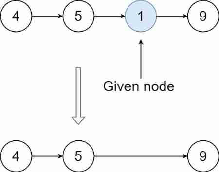
LeetCode#237. Delete nodes in the linked list
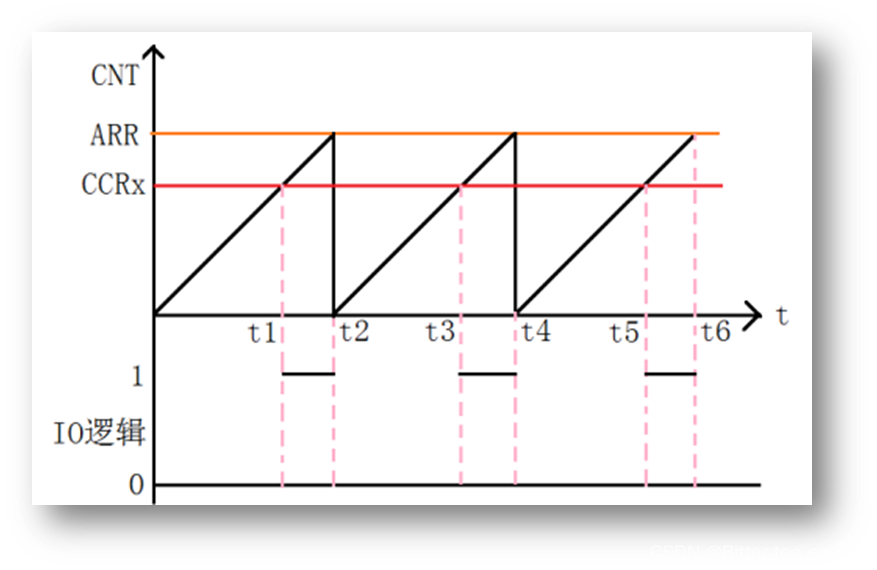
学习记录:如何进行PWM 输出
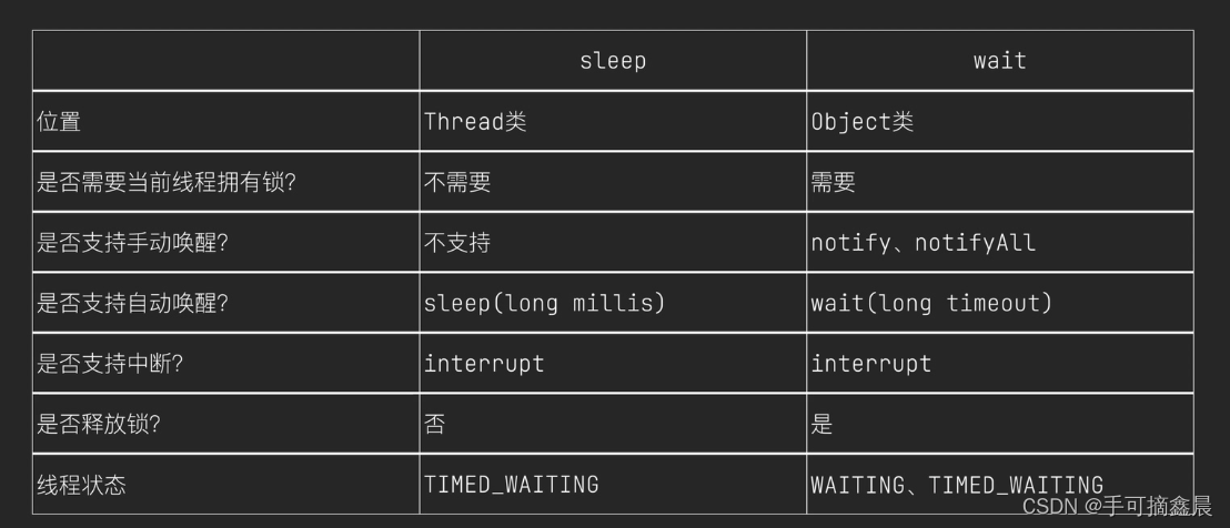
線程及線程池

Leetcode notes - dynamic planning -day7
STM32学习记录:玩转按键控制蜂鸣器和LED
ucore lab5
软件测试方法有哪些?带你看点不一样的东西

随机推荐
Should wildcard import be avoided- Should wildcard import be avoided?
Crawler series (9): item+pipeline data storage
Sorting odd and even subscripts respectively for leetcode simple problem
What if software testing is too busy to study?
FSM and I2C experiment report
Contest3145 - the 37th game of 2021 freshman individual training match_ A: Prizes
STM32 learning record: input capture application
遇到程序员不修改bug时怎么办?我教你
Word macro operation: convert the automatic number in the document into editable text type
Mysql database (I)
Brief description of compiler optimization level
Es6--- two methods of capturing promise status as failed
ucore lab6 调度器 实验报告
Brief introduction to libevent
想跳槽?面试软件测试需要掌握的7个技能你知道吗
Nest and merge new videos, and preset new video titles
LeetCode#62. Different paths
ucore lab5
LeetCode#412. Fizz Buzz
学习记录:理解 SysTick系统定时器,编写延时函数