当前位置:网站首页>Pandora IOT development board learning (HAL Library) - Experiment 2 buzzer experiment (learning notes)
Pandora IOT development board learning (HAL Library) - Experiment 2 buzzer experiment (learning notes)
2022-07-02 03:43:00 【Xiaohui_ Super】
This code refers to the punctual atomic routine
List of articles
Experimental function
Routine source code :(main.c)
This experiment realizes the continuous beeping of the buzzer , and LED The experiment is the same , The main knowledge point involved is operation GPIO.
#include "sys.h"
#include "delay.h"
#include "led.h"
#include "beep.h"

/********************************************************************************* ___ _ _____ _____ _ _ _____ _____ _ __ / _ \ | | |_ _|| ___|| \ | ||_ _|| ___|| | / / / /_\ \| | | | | |__ | \| | | | | |__ | |/ / | _ || | | | | __| | . ` | | | | __| | \ | | | || |_____| |_ | |___ | |\ | | | | |___ | |\ \ \_| |_/\_____/\___/ \____/ \_| \_/ \_/ \____/ \_| \_/ * ****************************************************************************** *  The punctual atoms  Pandora STM32L475 IoT Development board   experiment 2 *  Buzzer experiment  HAL Library version  *  Technical support :www.openedv.com *  Taobao shop :http://openedv.taobao.com *  Focus on wechat public platform wechat :" The punctual atoms ", Free access STM32 Information . *  Guangzhou Xingyi Electronic Technology Co., Ltd  *  author : The punctual atoms  @ALIENTEK * ******************************************************************************/

int main(void)
{

    HAL_Init();
    SystemClock_Config();	// Initialize the system clock to 80M
    delay_init(80); 		// Initialization delay function  80M The system clock

    LED_Init();				// initialization LED
    BEEP_Init();			// Initialize buzzer

    while(1)
    {

        BEEP(1);
        delay_ms(500);
        BEEP(0);
        delay_ms(1000);
    }
}
Code analysis
HAL_Init()
HAL_Init() The definition is as follows :( See notes for specific functions )
HAL_StatusTypeDef HAL_Init(void)
{

  HAL_StatusTypeDef  status = HAL_OK;

  /*  To configure  Flash  Prefetch , Instruction cache , Data caching  */
  /*  Default configuration is : Pre access is closed   Instruction cache and data cache are enabled  */
#if (INSTRUCTION_CACHE_ENABLE == 0) // Flash Enable pre access configuration , Can accelerate CPU Execution of code
   __HAL_FLASH_INSTRUCTION_CACHE_DISABLE();
#endif /* INSTRUCTION_CACHE_ENABLE */

#if (DATA_CACHE_ENABLE == 0)
   __HAL_FLASH_DATA_CACHE_DISABLE();
#endif /* DATA_CACHE_ENABLE */

#if (PREFETCH_ENABLE != 0)
  __HAL_FLASH_PREFETCH_BUFFER_ENABLE();
#endif /* PREFETCH_ENABLE */

  /* Set Interrupt Group Priority */
  HAL_NVIC_SetPriorityGrouping(NVIC_PRIORITYGROUP_2); //  To configure  NVIC  Priority groups

  /* Use SysTick as time base source and configure 1ms tick (default clock after Reset is MSI) */
  if (HAL_InitTick(TICK_INT_PRIORITY) != HAL_OK) // Initialize tick timer , The clock beat is set to  1ms
  {

    status = HAL_ERROR;
  }
  else
  {

    /* Init the low level hardware */
    HAL_MspInit(); //  Low speed peripheral initialization , such as  GPIO、 Interrupt, etc ( Use  STM32CubeMx  Low speed peripherals are initialized when generating code
                   //  The code is in this kind of function , In other cases, this function can be ignored
  }

  /* Return function status */
  return status;
}
HAL_InitTick()
Tick timer clock beat initialization function
__weak HAL_StatusTypeDef HAL_InitTick(uint32_t TickPriority)
{

  HAL_StatusTypeDef  status = HAL_OK;

  /*Configure the SysTick to have interrupt in 1ms time basis*/
  if (HAL_SYSTICK_Config(SystemCoreClock/1000UL) != 0U) //  The system clock /1000, The interruption period is  1ms
  {

    status = HAL_ERROR;
  }
  else
  {

    /*Configure the SysTick IRQ priority */
    HAL_NVIC_SetPriority(SysTick_IRQn, TickPriority, 0); //  Set the interrupt priority of the tick timer to the highest
  }

  /* Return function status */
  return status;
}
SystemClock_Config()
SystemClock_Config() The function is defined as follows :( See notes for specific functions , For reference only )
void SystemClock_Config(void)
{

    HAL_StatusTypeDef	ret = HAL_OK;

    RCC_OscInitTypeDef RCC_OscInitStruct; //  Define oscillator initialization structure variables
    RCC_ClkInitTypeDef RCC_ClkInitStruct; //  Define clock initialization structure variables

    __HAL_RCC_PWR_CLK_ENABLE(); //  Enable power control clock

    /*Initializes the CPU, AHB and APB busses clocks*/
    RCC_OscInitStruct.OscillatorType = RCC_OSCILLATORTYPE_HSE; //  take  HSE( External high-speed clock ) As a clock source
    RCC_OscInitStruct.HSEState = RCC_HSE_ON;  //  Turn on  HSE
    RCC_OscInitStruct.PLL.PLLState = RCC_PLL_ON; //  Turn on  PLL( PLL )
    RCC_OscInitStruct.PLL.PLLSource = RCC_PLLSOURCE_HSE; //  take  HSE  As  PLL  The clock source of
    RCC_OscInitStruct.PLL.PLLM = 1; // PLL-VCO  Input clock frequency division coefficient ,1  Express  2  frequency division (8 / 2 = 4M, The external crystal oscillator frequency of the development board is  8MHz)
    RCC_OscInitStruct.PLL.PLLN = 20; // PLL-VCO  Output clock frequency multiplication coefficient ,4 * 20 = 80M, That is, the output clock frequency is  80MHz
    RCC_OscInitStruct.PLL.PLLP = RCC_PLLP_DIV7; // SAI  Frequency division coefficient of clock
    RCC_OscInitStruct.PLL.PLLQ = RCC_PLLQ_DIV2; // SDMMC1, RNG  and  USB  Clock frequency division coefficient
    RCC_OscInitStruct.PLL.PLLR = RCC_PLLR_DIV2; //  Frequency division coefficient of the main system clock

    ret = HAL_RCC_OscConfig(&RCC_OscInitStruct); // Initialize clock configuration

    if(ret != HAL_OK)	while(1);

    /*Initializes the CPU, AHB and APB busses clocks*/
    RCC_ClkInitStruct.ClockType = RCC_CLOCKTYPE_HCLK | RCC_CLOCKTYPE_SYSCLK
                                  | RCC_CLOCKTYPE_PCLK1 | RCC_CLOCKTYPE_PCLK2; //  Configure all clocks at the same time
    RCC_ClkInitStruct.SYSCLKSource = RCC_SYSCLKSOURCE_PLLCLK; //  take  PLL  As the clock source of the system
    RCC_ClkInitStruct.AHBCLKDivider = RCC_SYSCLK_DIV1; // AHB  Regardless of the frequency
    RCC_ClkInitStruct.APB1CLKDivider = RCC_HCLK_DIV1; // APB1  Regardless of the frequency
    RCC_ClkInitStruct.APB2CLKDivider = RCC_HCLK_DIV1; // APB2  Regardless of the frequency


    ret	= HAL_RCC_ClockConfig(&RCC_ClkInitStruct, FLASH_LATENCY_4); //  Configure the initial structure variable of the clock ,
    // Use  Flash  Delay 4, Wait state ( Delay ) The quantity of should be according to CPU The clock (HCLK) Frequency and internal voltage range , How to
    // Please refer to the chip manual

    if(ret != HAL_OK)	while(1);

    /*Configure the main internal regulator output voltage*/
    ret = HAL_PWREx_ControlVoltageScaling(PWR_REGULATOR_VOLTAGE_SCALE1); // Internal register output voltage configuration
    //  Here is  HAL_PWREx_ControlVoltageScaling()  Part of the function description :
    //PWR_REGULATOR_VOLTAGE_SCALE1 Regulator voltage output range 1 mode, typical output voltage
    // at 1.2 V, system frequency up to 80 MHz.

    if(ret != HAL_OK)	while(1);
}
delay_init()
The tick timer is already HAL_Init() Initialization in , The following function is actually for fac_us Given a value ( At present, the operating system is not involved , Other code will not be studied for the time being ).
static u32 fac_us = 0;							//us Delay multiplier
/** * @brief  Initialization delay function ,SYSTICK The clock is fixed to AHB The clock  * * @param SYSCLK  System clock frequency  * * @return void */
void delay_init(u8 SYSCLK)
{

#if SYSTEM_SUPPORT_OS // If support is needed OS.
    u32 reload;
#endif
    HAL_SYSTICK_CLKSourceConfig(SYSTICK_CLKSOURCE_HCLK);//SysTick The frequency is HCLK
    fac_us = SYSCLK;						// Whether used or not OS,fac_us You need to use

#if SYSTEM_SUPPORT_OS // If support is needed OS.
    reload = SYSCLK;					  // The number of counts per second   Unit is K
    reload *= 1000000 / delay_ostickspersec;	// according to delay_ostickspersec Set the overflow time
    //reload by 24 Bit register , Maximum :16777216, stay 80M Next , about 209.7ms about
    fac_ms = 1000 / delay_ostickspersec;		// representative OS The minimum unit that can delay
    SysTick->CTRL |= SysTick_CTRL_TICKINT_Msk; // Turn on SYSTICK interrupt
    SysTick->LOAD = reload; 					// Every time 1/OS_TICKS_PER_SEC Second break once
    SysTick->CTRL |= SysTick_CTRL_ENABLE_Msk; // Turn on SYSTICK
#else
#endif
}
BEEP_Init()
/** * @brief  Buzzer  IO Initialization function  * * @param void * * @return void */
void BEEP_Init(void)
{

    GPIO_InitTypeDef GPIO_InitStruct;  //  Define a GPIO Initializing structure variables

    __HAL_RCC_GPIOB_CLK_ENABLE(); //  Can make GPIOE The clock of

    //PB2
    GPIO_InitStruct.Pin = GPIO_PIN_2; //  Set the corresponding pin
    GPIO_InitStruct.Mode = GPIO_MODE_OUTPUT_PP;  //  Push pull output mode
    GPIO_InitStruct.Pull = GPIO_PULLDOWN;  //  Default dropdown
    GPIO_InitStruct.Speed = GPIO_SPEED_FREQ_HIGH;  //  The speed is set to high speed (25 MHz to 50 MHz)
    HAL_GPIO_Init(GPIOB, &GPIO_InitStruct);  //  Initializing structure variables

    HAL_GPIO_WritePin(GPIOB, GPIO_PIN_2, GPIO_PIN_RESET);  // take  IO  Pull it down
}
delay_ms()
delay_ms() What runs in the is delay_us(), delay_us() Delay by ticking timer . above delay_init() Have already put fac_us Set up in order to 80, Tick timer counts 80 Time required 10-6 second ( The system clock is 80MHz), namely 1us.
/** * @brief  Delay milliseconds (ms) function  * * @param nms  How many milliseconds does it take  * * @return void */
void delay_ms(u16 nms)
{

    u32 i;

    for(i = 0; i < nms; i++) delay_us(1000);
}

/** * @brief  Delay microseconds (us) function  * * @remark nus:0~190887435( The maximum value is 2^32/[email protected]_us=22.5) * * @param nus  How many microseconds do you need to delay  * * @return void */
void delay_us(u32 nus)
{

    u32 ticks;
    u32 told, tnow, tcnt = 0;
    u32 reload = SysTick->LOAD;				//LOAD Value
    ticks = nus * fac_us; 					// The number of beats needed
    told = SysTick->VAL;        			// Counter value at the time of first entry

    while(1)
    {

        tnow = SysTick->VAL;

        if(tnow != told)
        {

            if(tnow < told)tcnt += told - tnow;	// Notice here SYSTICK It's a decreasing counter .
            else tcnt += reload - tnow + told;

            told = tnow;
            if(tcnt >= ticks)break;			// For more than / Equal to the time to delay , The exit .
        }
    }
}
BEEP()
The control function of the buzzer is a macro function , We used HAL_GPIO_WritePin() and HAL_GPIO_TogglePin() Two library functions .
#define BEEP(n) (n?HAL_GPIO_WritePin(GPIOB,GPIO_PIN_2,GPIO_PIN_SET):HAL_GPIO_WritePin(GPIOB,GPIO_PIN_2,GPIO_PIN_RESET))
#define BEEP_TogglePin HAL_GPIO_TogglePin(GPIOB,GPIO_PIN_2)
边栏推荐
- 数据库文件逻辑结构形式指的是什么
- 【小技巧】使用matlab GUI以对话框模式读取文件
- 蓝桥杯单片机数码管技巧
- 【DesignMode】建造者模式(Builder model)
- The fourth provincial competition of Bluebridge cup single chip microcomputer
- Getting started with MQ
- L'avènement de l'ère 5G, une brève discussion sur la vie passée et présente des communications mobiles
- regular expression
- SQL Yiwen get window function
- aaaaaaaaaaaaa
猜你喜欢

【IBDFE】基于IBDFE的频域均衡matlab仿真
The 7th Blue Bridge Cup single chip microcomputer provincial competition

The second game of the 12th provincial single chip microcomputer competition of the Blue Bridge Cup
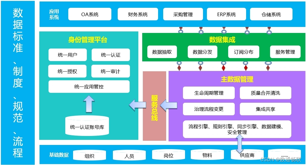
集成底座方案演示说明
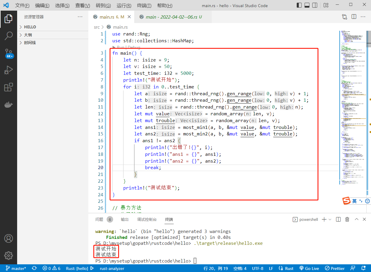
2022-07-01:某公司年会上,大家要玩一食发奖金游戏,一共有n个员工, 每个员工都有建设积分和捣乱积分, 他们需要排成一队,在队伍最前面的一定是老板,老板也有建设积分和捣乱积分, 排好队后,所有
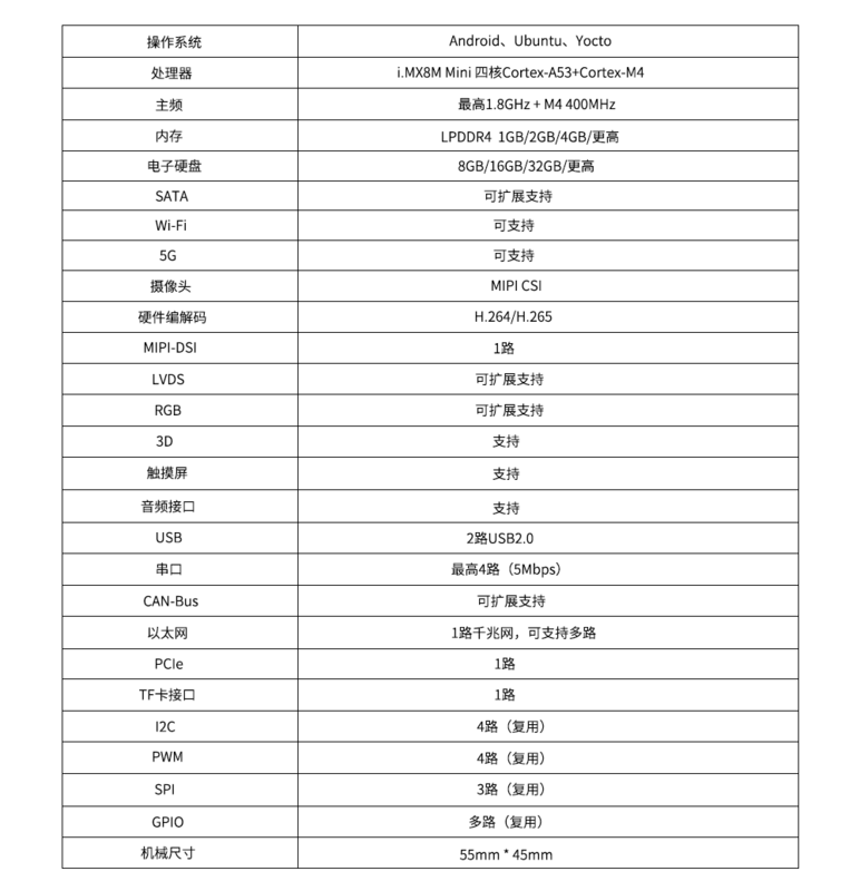
高性能 低功耗Cortex-A53核心板 | i.MX8M Mini

Gradle foundation | customize the plug-in and upload it to jitpack
![[designmode] builder model](/img/e8/855934d57eb6868a4d188b2bb1d188.png)
[designmode] builder model
Yan Rong looks at how to formulate a multi cloud strategy in the era of hybrid cloud
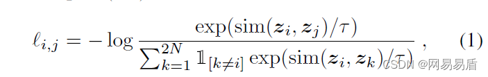
Knowing things by learning | self supervised learning helps improve the effect of content risk control
随机推荐
Set vscode. When double clicking, the selected string includes the $symbol - convenient for PHP operation
Oracle的md5
u本位合约爆仓清算解决方案建议
MySQL index, transaction and storage engine
The 9th Blue Bridge Cup single chip microcomputer provincial competition
Jetpack之LiveData扩展MediatorLiveData
Didi open source Delta: AI developers can easily train natural language models
[Li Kou brush questions] 15 Sum of three numbers (double pointer); 17. Letter combination of phone number (recursive backtracking)
Knowing things by learning | self supervised learning helps improve the effect of content risk control
Kotlin 基础学习13
Kotlin basic learning 17
VS2010插件NuGet
【直播回顾】战码先锋首期8节直播完美落幕,下期敬请期待!
傅里叶级数
< job search> process and signal
What kind of interview is more effective?
"Analysis of 43 cases of MATLAB neural network": Chapter 41 implementation of customized neural network -- personalized modeling and Simulation of neural network
[yolo3d]: real time detection of end-to-end 3D point cloud input
The second game of the 11th provincial single chip microcomputer competition of the Blue Bridge Cup
[punch in] flip the string (simple)