当前位置:网站首页>Get started with Aurora 8b/10b IP core in one day (5) -- learn from the official routine of framing interface
Get started with Aurora 8b/10b IP core in one day (5) -- learn from the official routine of framing interface
2022-07-02 03:33:00 【Lonely single knife】
List of articles
1、IP Core customization and generation of official routines
1.1、 Page 1 configuration : Physical layer and link layer information selection
1.2、 Page 2 configuration : Corresponding GT Physical location selection of transceiver
1.3、 Page 3 configuration : Shared logical location
1.4、 Official routine Example Design Generation
2.1、 The composition of official routines
2.2、Support modular (IP Core instantiation core module )
2.3、 Data generation module ( send out )
2.3.2、 Wait for initialization
2.3.4、 The state machine realizes frame sending
2.3.5、 Simulation and analysis
2.4、 Data verification module ( receive )
2.4.4、 Data reprocessing ( decoding )
2.4.6、 Data verification and error flag
Write it at the front
Xilinx Our technology ecology is doing very well , Basically all commonly used IP Nuclear has official routines (example design) For developers to learn , We don't need it for nothing , Today, let's go whoring with him for nothing ---- Start with the official routine and learn how to use this IP nucleus .
Series summary : One day Aurora 8B/10B IP nucleus ---- A summary ( Direct link )
1、IP Core customization and generation of official routines
First, build a new project , This project has nothing but generation Aurora 8B/10B IP Do nothing outside the core .IP The customization process of the core is as follows .
1.1、 Page 1 configuration : Physical layer and link layer information selection
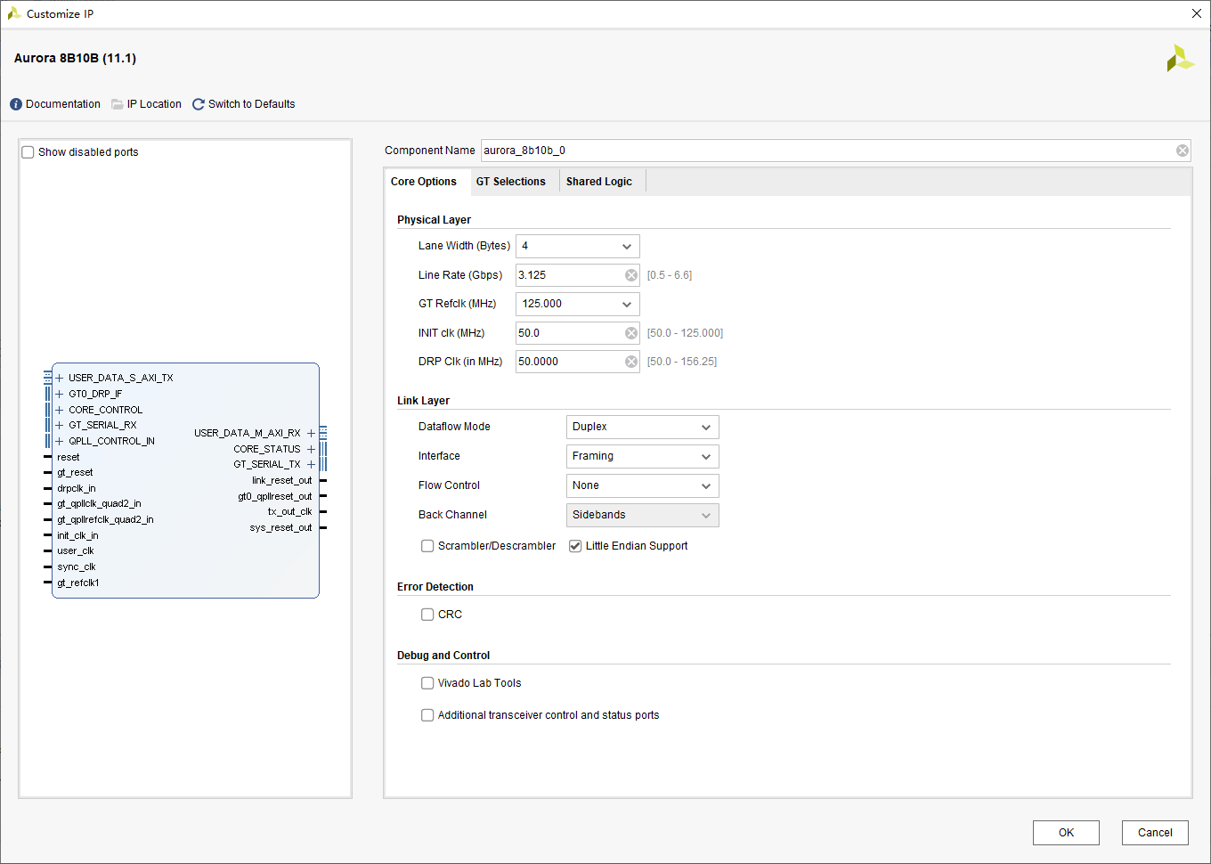
The physical layer Physical Layer:
- Lane Width: Link bit width , optional 2 perhaps 4, Company Bytes( Here, in order to lower the user's clock and facilitate subsequent clock constraints , choice 4bytes)
- Line Rate: Linear rate , Range 0.5~6.25Gbps, This is based on the needs of the project , choice 3.125Gbps
- GT Refclk: Serial transceiver GT The reference clock of , According to the actual situation of the board , We choose 125M
- INIT clk: Initialize the clock , stay GT Reset time ,user_clk It stopped working , recommend INIT CLK The clock frequency is below GT Reference clock , Choose the default 50M
- DRP clk: Dynamically reconfigure the clock , This function is not used much , Press default directly 50M Come on
The link layer Link Layer:
- Dataflow Mode: Data flow mode , Optional full duplex / Only receive / Send only , We choose full duplex mode here
- Interface:Framing/streaming Optional . This paper is about Framing Interface
- Flow Control: Flow control , Not so complicated for the time being , No election
- Back Channel: Only in simplex mode can you select (sidebands/timer Optional )
- Scrambler/Descrambler : Round the code / Unwinding , No choice here
- Little Endian Support : Check the small end mode , The small segment pattern corresponds to [31:0] This writing habit , The big end mode corresponds to [0:31] This writing habit
Commissioning and control ----Debug And Control:
Provides information such as ILA and VIO Etc IO Core and some other status indicator bits IP Monitor the running state of the system , For the convenience of testing , This kind of debugging interface is temporarily not selected .
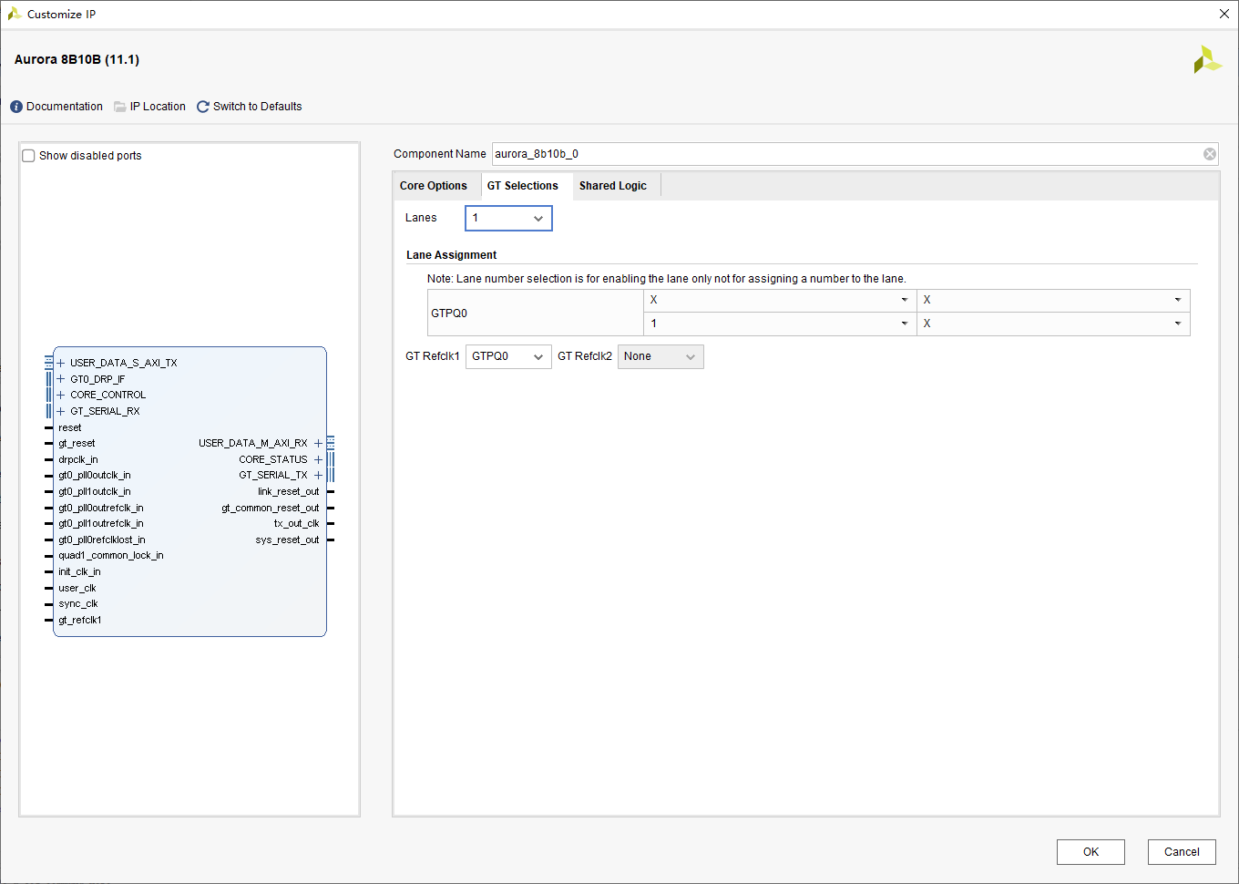
1.2、 Page 2 configuration : Corresponding GT Physical location selection of transceiver
Here according to their own FPGA On the chip GT Just choose according to the actual situation , We only simulate the test , Just choose a random channel :
1.3、 Page 3 configuration : Shared logical location
Such as clock and reset logic , Is it in the core or in the example project ( majority IP nucleus Xilinx Will provide routines for reference ). It is recommended to set the sharing logic in the official routine , So we can follow up on IP The use of the core can be directly based on the official routine with a little modification .

1.4、 Official routine Example Design Generation
take IP After the core is customized and integrated , You can generate official routines Example Design 了 :

2、 Official routine analysis
The analysis of official routines mainly refers to the generated source code and 《PG046:Aurora 8B/10B v11.1 LogiCORE IP Product Guide》. Through the above information , We can master IP How to use the core and understand the general composition of official routines .
2.1、 The composition of official routines
Let's first look at the logical hierarchy of generating routine files :
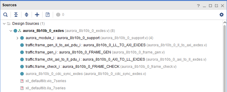
The level of design documents is not obvious , Let's call up the structure diagram and have a look :

In this way, you can basically understand :
- support modular : Core module , Contains the right IP、GT And so on ; In our subsequent applications, this part does not need to be modified
- frame_gen: Data generation module , use LFSR To generate pseudo-random sequences ; Later, in our application, this part can be replaced by our data input module ( It is suggested to join FIFO, This makes the code more reusable )
- frame_check: Data verification module , Check the received data to verify the correctness of transmission ; Later, in our application, this part can be replaced by our data inspection module or deleted
- LL_AXI:LL The bus turns AXI Bus ( It is said that the original interface of this routine is LL Interface , Back Xilinx In order to promote AXI Bus , Therefore, this routine directly adds a bus conversion module on the basis of the original code )
- AXI_LL:AXI The bus turns LL Bus , The reason as above
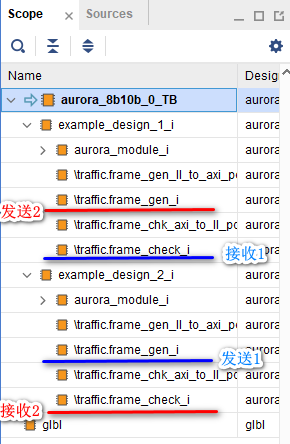
The content of the simulation part is easy to understand according to the level -- Called the routine twice . according to Xilinx Consistent urination , It's easy to guess that this is a loopback test again . In fact, you can also see one or two from the manual :
- Testbench Instantiated two routines
- routine 1 After the data is generated, it is processed by Aurora Sent to routine 2 Detection module of , And feed the results back to Testbench
- routine 2 After the data is generated, it is processed by Aurora Sent to routine 1 Detection module of , And feed the results back to Testbench

2.2、Support modular (IP Core instantiation core module )
I don't say much nonsense , Let's start with Support The composition of the module :

It is not difficult to see from the composition ,Support The main function of the module is instantiation aurora IP Core and turn the clock 、 Reset and other signals are packaged together . So we don't need to be right Support Learn more about the internal structure of the module , Just look at its external interface and you can almost use it .Support Sub module under module :
- clock_module: Clock processing generation module
- support_reset_logic_i: Reset the logic generation module
- gt_common_support: And GT The clock associated with the transceiver generates its other signals
- Aurora IP Nuclear modules
2.3、 Data generation module ( send out )
As mentioned above, as long as we replace the data generation module with our own files, we can realize the secondary creation of official routines , To complete the Aurora IP I've made good use of it . Then we naturally need to explore its source code . The complete code is as follows :
`timescale 1 ns / 1 ps
`define DLY #1

module aurora_8b10b_0_FRAME_GEN
(
    // User Interface
    TX_D,
    TX_REM,
    TX_SOF_N,
    TX_EOF_N,
    TX_SRC_RDY_N,
    TX_DST_RDY_N,
    // System Interface
    USER_CLK,
    RESET,
    CHANNEL_UP
);
//*****************************Parameter Declarations****************************

//***********************************Port Declarations*******************************
// User Interface
output  [0:31]     TX_D;
output  [0:1]      TX_REM;
output             TX_SOF_N;
output             TX_EOF_N;
output             TX_SRC_RDY_N;
input              TX_DST_RDY_N;
// System Interface
input              USER_CLK;
input              RESET;
input              CHANNEL_UP;
//***************************External Register Declarations***************************
reg                TX_SRC_RDY_N;
reg                TX_SOF_N;
reg                TX_EOF_N;
//***************************Internal Register Declarations***************************
reg     [0:15]     data_lfsr_r;
reg     [0:7]      frame_size_r;
reg     [0:7]      bytes_sent_r;
reg     [0:3]      ifg_size_r;
//State registers for one-hot state machine
reg                idle_r;
reg                single_cycle_frame_r;
reg                sof_r;
reg                data_cycle_r;
reg                eof_r;
wire               reset_c;
//*********************************Wire Declarations**********************************
wire               ifg_done_c;
//Next state signals for one-hot state machine
wire               next_idle_c;
wire               next_single_cycle_frame_c;
wire               next_sof_c;
wire               next_data_cycle_c;
wire               next_eof_c;
wire       		   dly_data_xfer;
reg [4:0]  		   channel_up_cnt;
//*********************************Main Body of Code**********************************
  always @ (posedge USER_CLK)
  begin
    if(RESET)
        channel_up_cnt <= `DLY 5'd0;
    else if(CHANNEL_UP)
      if(&channel_up_cnt)
        channel_up_cnt <= `DLY channel_up_cnt;
      else
        channel_up_cnt <= `DLY channel_up_cnt + 1'b1;
    else
      channel_up_cnt <= `DLY 5'd0;
  end

  assign dly_data_xfer = (&channel_up_cnt);

  //Generate RESET signal when Aurora channel is not ready
  assign reset_c = RESET || !dly_data_xfer;

    //______________________________ Transmit Data  __________________________________
    //Generate random data using XNOR feedback LFSR
    always @(posedge USER_CLK)
        if(reset_c)
        begin
            data_lfsr_r          <=  `DLY    16'hABCD;  //random seed value
        end
        else if(!TX_DST_RDY_N && !idle_r)
        begin
            data_lfsr_r          <=  `DLY    {!{data_lfsr_r[3]^data_lfsr_r[12]^data_lfsr_r[14]^data_lfsr_r[15]},
                                data_lfsr_r[0:14]};
        end

    //Connect TX_D to the DATA LFSR
    assign  TX_D    =   {2{data_lfsr_r}};
    //Tie DATA LFSR to REM to generate random words
    assign  TX_REM  = data_lfsr_r[0:1];
    //Use a counter to determine the size of the next frame to send
    always @(posedge USER_CLK)
        if(reset_c)
            frame_size_r    <=  `DLY    8'h00;
        else if(single_cycle_frame_r || eof_r)
            frame_size_r    <=  `DLY    frame_size_r + 1;

    //Use a second counter to determine how many bytes of the frame have already been sent
    always @(posedge USER_CLK)
        if(reset_c)
            bytes_sent_r    <=  `DLY    8'h00;
        else if(sof_r)
            bytes_sent_r    <=  `DLY    8'h01;
        else if(!TX_DST_RDY_N && !idle_r)
            bytes_sent_r    <=  `DLY    bytes_sent_r + 1;

    //Use a freerunning counter to determine the IFG
    always @(posedge USER_CLK)
        if(reset_c)
            ifg_size_r      <=  `DLY    4'h0;
        else
            ifg_size_r      <=  `DLY    ifg_size_r + 1;
    //IFG is done when ifg_size register is 0
    assign  ifg_done_c  =   (ifg_size_r == 4'h0);

    //_____________________________ Framing State machine______________________________
    //Use a state machine to determine whether to start a frame, end a frame, send
    //data or send nothing
    //State registers for 1-hot state machine
    always @(posedge USER_CLK)
        if(reset_c)
        begin
            idle_r                  <=  `DLY    1'b1;
            single_cycle_frame_r    <=  `DLY    1'b0;
            sof_r                   <=  `DLY    1'b0;
            data_cycle_r            <=  `DLY    1'b0;
            eof_r                   <=  `DLY    1'b0;
        end
        else if(!TX_DST_RDY_N)
        begin
            idle_r                  <=  `DLY    next_idle_c;
            single_cycle_frame_r    <=  `DLY    next_single_cycle_frame_c;
            sof_r                   <=  `DLY    next_sof_c;
            data_cycle_r            <=  `DLY    next_data_cycle_c;
            eof_r                   <=  `DLY    next_eof_c;
        end

    //Nextstate logic for 1-hot state machine
    assign  next_idle_c                 =   !ifg_done_c &&
                                            (single_cycle_frame_r || eof_r || idle_r);

    assign  next_single_cycle_frame_c   =   (ifg_done_c && (frame_size_r == 0)) &&
                                            (idle_r || single_cycle_frame_r || eof_r);

    assign  next_sof_c                  =   (ifg_done_c && (frame_size_r != 0)) &&
                                            (idle_r || single_cycle_frame_r || eof_r);

    assign  next_data_cycle_c           =   (frame_size_r != bytes_sent_r) &&
                                            (sof_r || data_cycle_r);

    assign  next_eof_c                  =   (frame_size_r == bytes_sent_r) &&
                                            (sof_r || data_cycle_r);

    //Output logic for 1-hot state machine
    always @(posedge USER_CLK)
        if(reset_c)
        begin
            TX_SOF_N        <=  `DLY    1'b1;
            TX_EOF_N        <=  `DLY    1'b1;
            TX_SRC_RDY_N    <=  `DLY    1'b1;
        end
        else if(!TX_DST_RDY_N)
        begin
            TX_SOF_N        <=  `DLY    !(sof_r || single_cycle_frame_r);
            TX_EOF_N        <=  `DLY    !(eof_r || single_cycle_frame_r);
            TX_SRC_RDY_N    <=  `DLY    idle_r;
        end

endmodule
Not much code , Let's just dismantle it section by section .
2.3.1、 port
Let's first look at the standards of official documents Framing Interface , Then compare the code .
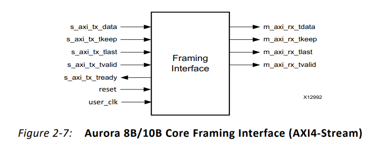
// User Interface
output  [0:31]     TX_D;			// Data to send
output  [0:1]      TX_REM;			// Random words
output             TX_SOF_N;		// Frame header indication , Low efficiency
output             TX_EOF_N;		// End of frame indication , Low efficiency
output             TX_SRC_RDY_N;	//tvalid
input              TX_DST_RDY_N;	//tready
// System Interface
input              USER_CLK;		// User clock
input              RESET; 			// Reset
input              CHANNEL_UP;		// Channel effective signal , Highly effective
2.3.2、 Wait for initialization
//CHANNEL_UP When you get up ,channel_up_cnt Count 16 Clock cycles
  always @ (posedge USER_CLK)
  begin
    if(RESET)
        channel_up_cnt <= `DLY 5'd0;
    else if(CHANNEL_UP)
      if(&channel_up_cnt)
        channel_up_cnt <= `DLY channel_up_cnt;
      else
        channel_up_cnt <= `DLY channel_up_cnt + 1'b1;
    else
      channel_up_cnt <= `DLY 5'd0;
  end

  assign dly_data_xfer = (&channel_up_cnt);		//channel_up_cnt Count 16 After the clock cycle is full , pull up dly_data_xfer

  //Generate RESET signal when Aurora channel is not ready
  assign reset_c = RESET || !dly_data_xfer;		//
If CHANNEL_UP I haven't got up yet , that channel_up_cnt Will be all 0, and dly_data_xfer by 0, So the sentence assign reset_c = RESET || !dly_data_xfer Hang up ,reset_c Constant for the 1, So it has been in the reset state .
When CHANNEL_UP When you get up ,channel_up_cnt It takes some time to count to 5‘b11111, then dly_data_xfer by 1, So at this time assign reset_c = RESET || !dly_data_xfer Equivalent to assign reset_c = RESET, namely RESET control reset_c The signal . and RESET Generally in CHANNEL_UP After getting up, it is in the invalid reset state , So at this time, the channel enters the normal working mode .
2.3.3、LFSR Use
    //Generate random data using XNOR feedback LFSR
    always @(posedge USER_CLK)
        if(reset_c)
        begin
            data_lfsr_r          <=  `DLY    16'hABCD;  //random seed value
        end
        else if(!TX_DST_RDY_N && !idle_r)
        begin
            data_lfsr_r          <=  `DLY    {!{data_lfsr_r[3]^data_lfsr_r[12]^data_lfsr_r[14]^data_lfsr_r[15]},
                                data_lfsr_r[0:14]};
        end

    //Connect TX_D to the DATA LFSR
    assign  TX_D    =   {2{data_lfsr_r}};
    //Tie DATA LFSR to REM to generate random words
    assign  TX_REM  = data_lfsr_r[0:1];
About LFSR May refer to :FPGA Linear feedback shift register LFSR
The seed loaded at this time is 16'hABCD.
2.3.4、 The state machine realizes frame sending
This module uses a state machine to describe the sending process . It should be noted that the writing method of the state machine is different from the three-stage state machine we usually contact , So it looks a little awkward , Like its 5 The states are as follows :
    //Use a state machine to determine whether to start a frame, end a frame, send
    //data or send nothing
    //State registers for 1-hot state machine
    always @(posedge USER_CLK)
        if(reset_c)
        begin
            idle_r                  <=  `DLY    1'b1;
            single_cycle_frame_r    <=  `DLY    1'b0;
            sof_r                   <=  `DLY    1'b0;
            data_cycle_r            <=  `DLY    1'b0;
            eof_r                   <=  `DLY    1'b0;
        end
        else if(!TX_DST_RDY_N)
        begin
            idle_r                  <=  `DLY    next_idle_c;
            single_cycle_frame_r    <=  `DLY    next_single_cycle_frame_c;
            sof_r                   <=  `DLY    next_sof_c;
            data_cycle_r            <=  `DLY    next_data_cycle_c;
            eof_r                   <=  `DLY    next_eof_c;
Then the state transition conditions are as follows :
    //Nextstate logic for 1-hot state machine
    assign  next_idle_c                 =   !ifg_done_c &&
                                            (single_cycle_frame_r || eof_r || idle_r);

    assign  next_single_cycle_frame_c   =   (ifg_done_c && (frame_size_r == 0)) &&
                                            (idle_r || single_cycle_frame_r || eof_r);

    assign  next_sof_c                  =   (ifg_done_c && (frame_size_r != 0)) &&
                                            (idle_r || single_cycle_frame_r || eof_r);

    assign  next_data_cycle_c           =   (frame_size_r != bytes_sent_r) &&
                                            (sof_r || data_cycle_r);

    assign  next_eof_c                  =   (frame_size_r == bytes_sent_r) &&
                                            (sof_r || data_cycle_r);
There are some parameters that need to be understood in order to master the jump of state machine :
(1)ifg_done_c
    //Use a freerunning counter to determine the IFG
    always @(posedge USER_CLK)
        if(reset_c)
            ifg_size_r      <=  `DLY    4'h0;
        else
            ifg_size_r      <=  `DLY    ifg_size_r + 1;
    //IFG is done when ifg_size register is 0
    assign  ifg_done_c  =   (ifg_size_r == 4'h0);
Built a 00000~11111 A counter that counts , Whenever the counter value is 0 That is to pull up ifg_done_c
(2) frame_size_r
    //Use a counter to determine the size of the next frame to send
    always @(posedge USER_CLK)
        if(reset_c)
            frame_size_r    <=  `DLY    8'h00;
        else if(single_cycle_frame_r || eof_r)
            frame_size_r    <=  `DLY    frame_size_r + 1;
frame_size_r Is a counter of the size of a frame of data , The initial value is 0, When the first frame is sent or one frame is sent, it is accumulated 1, After that , The first transmission length is 1 A frame of data , The second time, the transmission length is 2 A frame of data , And so on .
(3)bytes_sent_r
    //Use a second counter to determine how many bytes of the frame have already been sent
    always @(posedge USER_CLK)
        if(reset_c)
            bytes_sent_r    <=  `DLY    8'h00;
        else if(sof_r)
            bytes_sent_r    <=  `DLY    8'h01;
        else if(!TX_DST_RDY_N && !idle_r)
            bytes_sent_r    <=  `DLY    bytes_sent_r + 1;
bytes_sent_r It is used to calculate the current frame data and how many BYTE The data of is sent out .
(4) Output
//Output logic for 1-hot state machine
always @(posedge USER_CLK)
if(reset_c)
begin
TX_SOF_N <= `DLY 1'b1;
TX_EOF_N <= `DLY 1'b1;
TX_SRC_RDY_N <= `DLY 1'b1;
end
else if(!TX_DST_RDY_N)
begin
TX_SOF_N <= `DLY !(sof_r || single_cycle_frame_r);
TX_EOF_N <= `DLY !(eof_r || single_cycle_frame_r);
TX_SRC_RDY_N <= `DLY idle_r;
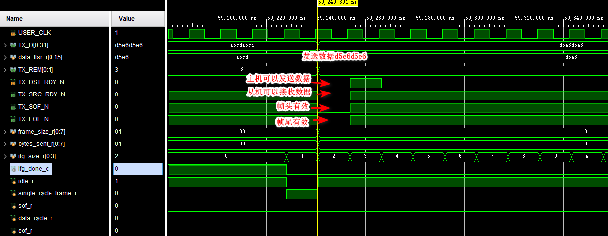
end2.3.5、 Simulation and analysis
The state transition diagram is drawn for you :

With these conditions , We can infer how the whole state machine works according to the simulation :
(1) Power on reset
Power on reset , wait for IP Core initialization complete , And continue to delay for a period of time after its initialization .

(2) The initial state
After power on and reset successfully , The state machine is in state idle_r, At this time, the frame size frame_size_r by 0, Counter ifg_size_r by 0, therefore ifg_done_c by 1, The status will jump to single_cycle_frame_r

(3) Send a frame of data ( Single data )
Frame size frame_size_r+1, At this time, no conditions are met , Stay in this state ; At this time, send single frame data
(4) Send a frame of data ( Multiple data )
Counter ifg_size_r Count to 11111 Then jump to 00000,ifg_done_c by 1, And the frame size frame_size_r by 1( Not 0), So the state will jump to sof
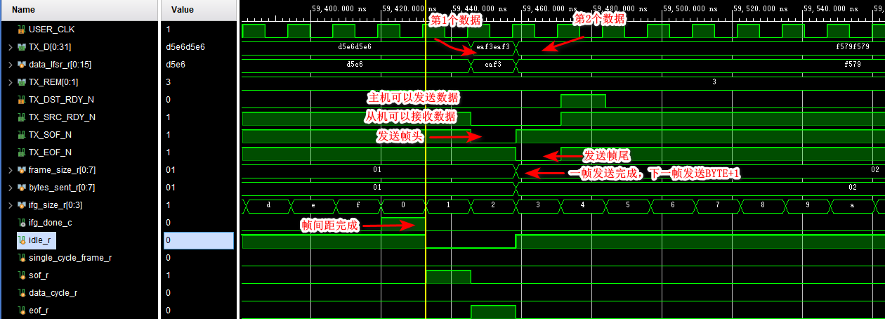
(5) Send a frame of data ( Multiple data )
thereafter , Each frame of data sent will be smaller than the previous frame 1 individual BYTE, Until the end of the simulation .
(6) summary
therefore , The function of the sending module is actually : Send... First 1 individual BYTE A frame of data , Send after an interval 2 individual BYTE A frame of data , It will happen after a period of time 3 individual BYTE A frame of data , And so on ······ The data sent is using LFSR To generate a pseudo-random sequence .
2.4、 Data verification module ( receive )
Since there is a sending module , There must also be reception ( check ) Module , Otherwise, how can I know whether you sent it correctly ?
`timescale 1 ns / 1 ps
`define DLY #1

module aurora_8b10b_0_FRAME_CHECK
(
    // User Interface
    RX_D,
    RX_REM,
    RX_SOF_N,
    RX_EOF_N,
    RX_SRC_RDY_N,
    // System Interface
    USER_CLK,
    RESET,
    CHANNEL_UP,
    ERR_COUNT
);
//***********************************Port Declarations*******************************
// User Interface
input   [0:31]     RX_D;
input   [0:1]      RX_REM;
input              RX_SOF_N;
input              RX_EOF_N;
input              RX_SRC_RDY_N;
// System Interface
input              USER_CLK;
input              RESET;
input              CHANNEL_UP;
output  [0:7]      ERR_COUNT;
//***************************Internal Register Declarations***************************
// Slack registers
reg   [0:31]     	RX_D_SLACK;
reg   [0:1]      	RX_REM_1SLACK;
reg   [0:1]      	RX_REM_2SLACK;
reg              	RX_SOF_N_SLACK;
reg              	RX_EOF_N_SLACK;
reg              	RX_SRC_RDY_N_SLACK;
reg     [0:8]      	err_count_r = 9'd0;
reg                	data_in_frame_r;
reg                	data_valid_r;
reg     [0:31]     	RX_D_R;
reg     [0:31]     	pdu_cmp_data_r;
// RX Data registers
reg     [0:15]      data_lfsr_r;
//*********************************Wire Declarations**********************************
wire               reset_c;
wire    [0:31]     data_lfsr_concat_w;
wire               data_valid_c;
wire               data_in_frame_c;
wire               data_err_detected_c;
reg                data_err_detected_r;
//*********************************Main Body of Code**********************************
//Generate RESET signal when Aurora channel is not ready
  assign reset_c = RESET;

// SLACK registers
always @ (posedge USER_CLK)
begin
  RX_D_SLACK          <= `DLY RX_D;
  RX_SRC_RDY_N_SLACK  <= `DLY RX_SRC_RDY_N;
  RX_REM_1SLACK       <= `DLY RX_REM;
  RX_REM_2SLACK       <= `DLY RX_REM;
  RX_SOF_N_SLACK      <= `DLY RX_SOF_N;
  RX_EOF_N_SLACK      <= `DLY RX_EOF_N;
end

    //______________________________ Capture incoming data ___________________________
    //Data is valid when RX_SRC_RDY_N is asserted and data is arriving within a frame
    assign  data_valid_c    =   data_in_frame_c && !RX_SRC_RDY_N_SLACK;

    //Data is in a frame if it is a single cycle frame or a multi_cycle frame has started
    assign  data_in_frame_c  =   data_in_frame_r  ||  (!RX_SRC_RDY_N_SLACK && !RX_SOF_N_SLACK);

    //RX Data in the pdu_cmp_data_r register is valid
    //only if it was valid when captured and had no error
    always @(posedge USER_CLK)
        if(reset_c)
           data_valid_r    <=  `DLY    1'b0;
        else if(CHANNEL_UP)
           data_valid_r    <=  `DLY    data_valid_c && !data_err_detected_c;
        else
           data_valid_r    <=  `DLY    1'b0;

    //Start a multicycle frame when a frame starts without ending on the same cycle. End
    //the frame when an EOF is detected
    always @(posedge USER_CLK)
        if(reset_c)
            data_in_frame_r  <=  `DLY    1'b0;
        else if(CHANNEL_UP)
        begin
          if(!data_in_frame_r && !RX_SOF_N_SLACK && !RX_SRC_RDY_N_SLACK && RX_EOF_N_SLACK)	//1 Frame start
            data_in_frame_r  <=  `DLY    1'b1;
          else if(data_in_frame_r && !RX_SRC_RDY_N_SLACK && !RX_EOF_N_SLACK)				//1 End of the frame
            data_in_frame_r  <=  `DLY    1'b0;
        end

    //Register and decode the RX_D data with RX_REM bus
    always @ (posedge USER_CLK)
    begin
      if((!RX_EOF_N_SLACK) && (!RX_SRC_RDY_N_SLACK))
      begin
        case(RX_REM_1SLACK)
          2'd0 : RX_D_R <=  `DLY {RX_D_SLACK[0:7], 24'b0};
          2'd1 : RX_D_R <=  `DLY {RX_D_SLACK[0:15], 16'b0};
          2'd2 : RX_D_R <=  `DLY {RX_D_SLACK[0:23], 8'b0};
          2'd3 : RX_D_R <=  `DLY RX_D_SLACK;
          default : RX_D_R  <=  `DLY RX_D_SLACK;
	endcase
      end
      else if(!RX_SRC_RDY_N_SLACK)
        RX_D_R          <=  `DLY    RX_D_SLACK;
    end

    //Calculate the expected frame data
    always @ (posedge USER_CLK)
    begin
      if(reset_c)
        pdu_cmp_data_r <= `DLY {2{16'hD5E6}};
      else if(CHANNEL_UP)
      begin
        if(data_valid_c && !RX_EOF_N_SLACK)
        begin
          case(RX_REM_2SLACK)
            2'd0 : pdu_cmp_data_r <=  `DLY {data_lfsr_concat_w[0:7], 24'b0};
            2'd1 : pdu_cmp_data_r <=  `DLY {data_lfsr_concat_w[0:15], 16'b0};
            2'd2 : pdu_cmp_data_r <=  `DLY {data_lfsr_concat_w[0:23], 8'b0};
            2'd3 : pdu_cmp_data_r <=  `DLY data_lfsr_concat_w;
            default : pdu_cmp_data_r <=  `DLY data_lfsr_concat_w;
	  endcase
        end
        else if(data_valid_c)
          pdu_cmp_data_r <=  `DLY data_lfsr_concat_w;
        end
      end

    //generate expected RX_D using LFSR
    always @(posedge USER_CLK)
        if(reset_c)
        begin
            data_lfsr_r          <=  `DLY    16'hD5E6;  //random seed value
        end
        else if(CHANNEL_UP)
        begin
          if(data_valid_c)
           data_lfsr_r          <=  `DLY    {!{data_lfsr_r[3]^data_lfsr_r[12]^data_lfsr_r[14]^data_lfsr_r[15]},
                                data_lfsr_r[0:14]};
        end
        else
        begin
           data_lfsr_r          <=  `DLY    16'hD5E6;  //random seed value
        end

    assign data_lfsr_concat_w = {2{data_lfsr_r}};

    //___________________________ Check incoming data for errors __________________________
    //An error is detected when LFSR generated RX data from the pdu_cmp_data_r register,
    //does not match valid data from the RX_D port
    assign  data_err_detected_c    = (data_valid_r && (RX_D_R != pdu_cmp_data_r));

    //We register the data_err_detected_c signal for use with the error counter logic
    always @(posedge USER_CLK)
      data_err_detected_r    <=  `DLY    data_err_detected_c;

    //Compare the incoming data with calculated expected data.
    //Increment the ERROR COUNTER if mismatch occurs.
    //Stop the ERROR COUNTER once it reaches its max value (i.e. 255)
    always @(posedge USER_CLK)
        if(CHANNEL_UP)
        begin
          if(&err_count_r)
            err_count_r       <=  `DLY    err_count_r;
          else if(data_err_detected_r)
            err_count_r       <=  `DLY    err_count_r + 1;
        end
	else
        begin
          err_count_r       <=  `DLY    9'd0;
	end

    //Here we connect the lower 8 bits of the count (the MSbit is used only to check when the counter reaches
    //max value) to the module output
    assign  ERR_COUNT =   err_count_r[1:8];

endmodule
2.4.1、 Port and deposit
// User Interface
input   [0:31]     RX_D;
input   [0:1]      RX_REM;
input              RX_SOF_N;
input              RX_EOF_N;
input              RX_SRC_RDY_N;
// System Interface
input              USER_CLK;
input              RESET;
input              CHANNEL_UP;
output  [0:7]      ERR_COUNT;


// SLACK registers
always @ (posedge USER_CLK)
begin
  RX_D_SLACK          <= `DLY RX_D;
  RX_SRC_RDY_N_SLACK  <= `DLY RX_SRC_RDY_N;
  RX_REM_1SLACK       <= `DLY RX_REM;
  RX_REM_2SLACK       <= `DLY RX_REM;
  RX_SOF_N_SLACK      <= `DLY RX_SOF_N;
  RX_EOF_N_SLACK      <= `DLY RX_EOF_N;
end
The port signal basically corresponds to the sending module one by one , Only one more error count output . Then all the input signals are stored for a beat , To improve timing .
2.4.2、 Reset
//Generate RESET signal when Aurora channel is not ready
  assign reset_c = RESET;
Reset and use it directly , There is no problem of unstable initialization . Because when the sender can send data normally , It indicates that the data link has been successfully established .
2.4.3、 Data validity judgment
    //Data is valid when RX_SRC_RDY_N is asserted and data is arriving within a frame
    assign  data_valid_c    =   data_in_frame_c && !RX_SRC_RDY_N_SLACK;

    //Data is in a frame if it is a single cycle frame or a multi_cycle frame has started
    assign  data_in_frame_c  =   data_in_frame_r  ||  (!RX_SRC_RDY_N_SLACK && !RX_SOF_N_SLACK);

    //RX Data in the pdu_cmp_data_r register is valid
    //only if it was valid when captured and had no error
    always @(posedge USER_CLK)
        if(reset_c)
           data_valid_r    <=  `DLY    1'b0;
        else if(CHANNEL_UP)
           data_valid_r    <=  `DLY    data_valid_c && !data_err_detected_c;
        else
           data_valid_r    <=  `DLY    1'b0;

    //Start a multicycle frame when a frame starts without ending on the same cycle. End
    //the frame when an EOF is detected
    always @(posedge USER_CLK)
        if(reset_c)
            data_in_frame_r  <=  `DLY    1'b0;
        else if(CHANNEL_UP)
        begin
          if(!data_in_frame_r && !RX_SOF_N_SLACK && !RX_SRC_RDY_N_SLACK && RX_EOF_N_SLACK)	//1 Frame start
            data_in_frame_r  <=  `DLY    1'b1;
          else if(data_in_frame_r && !RX_SRC_RDY_N_SLACK && !RX_EOF_N_SLACK)				//1 End of the frame
            data_in_frame_r  <=  `DLY    1'b0;
        end
According to frame header 、 The end of frame signal is used to construct a signal that represents the validity of a frame data .
2.4.4、 Data reprocessing ( decoding )
    //Register and decode the RX_D data with RX_REM bus
    always @ (posedge USER_CLK)
    begin
      if((!RX_EOF_N_SLACK) && (!RX_SRC_RDY_N_SLACK))
      begin
        case(RX_REM_1SLACK)
          2'd0 : RX_D_R <=  `DLY {RX_D_SLACK[0:7], 24'b0};
          2'd1 : RX_D_R <=  `DLY {RX_D_SLACK[0:15], 16'b0};
          2'd2 : RX_D_R <=  `DLY {RX_D_SLACK[0:23], 8'b0};
          2'd3 : RX_D_R <=  `DLY RX_D_SLACK;
          default : RX_D_R  <=  `DLY RX_D_SLACK;
	endcase
      end
      else if(!RX_SRC_RDY_N_SLACK)
        RX_D_R          <=  `DLY    RX_D_SLACK;
    end
according to RX_REM_1SLACK The signal reprocesses the received data ( Similar to the decoding process ), It can improve the randomness of data .RX_REM_1SLACK The signal is RX_REM The signal after being deposited , and RX_REM The signal is sent by a sender 2bit random number .
2.4.5、LFSR The data generated
    //Calculate the expected frame data
    always @ (posedge USER_CLK)
    begin
      if(reset_c)
        pdu_cmp_data_r <= `DLY {2{16'hD5E6}};
      else if(CHANNEL_UP)
      begin
        if(data_valid_c && !RX_EOF_N_SLACK)
        begin
          case(RX_REM_2SLACK)
            2'd0 : pdu_cmp_data_r <=  `DLY {data_lfsr_concat_w[0:7], 24'b0};
            2'd1 : pdu_cmp_data_r <=  `DLY {data_lfsr_concat_w[0:15], 16'b0};
            2'd2 : pdu_cmp_data_r <=  `DLY {data_lfsr_concat_w[0:23], 8'b0};
            2'd3 : pdu_cmp_data_r <=  `DLY data_lfsr_concat_w;
            default : pdu_cmp_data_r <=  `DLY data_lfsr_concat_w;
	  endcase
        end
        else if(data_valid_c)
          pdu_cmp_data_r <=  `DLY data_lfsr_concat_w;
        end
      end

    //generate expected RX_D using LFSR
    always @(posedge USER_CLK)
        if(reset_c)
        begin
            data_lfsr_r          <=  `DLY    16'hD5E6;  //random seed value
        end
        else if(CHANNEL_UP)
        begin
          if(data_valid_c)
           data_lfsr_r          <=  `DLY    {!{data_lfsr_r[3]^data_lfsr_r[12]^data_lfsr_r[14]^data_lfsr_r[15]},
                                data_lfsr_r[0:14]};
        end
        else
        begin
           data_lfsr_r          <=  `DLY    16'hD5E6;  //random seed value
        end

    assign data_lfsr_concat_w = {2{data_lfsr_r}};
The data at the sending end is LFSR Generated , Of course, the verifier should use the same method to generate data , Easy to compare , To judge the sending -- Whether the receiving process is normal .
2.4.6、 Data verification and error flag
    //An error is detected when LFSR generated RX data from the pdu_cmp_data_r register,
    //does not match valid data from the RX_D port
    assign  data_err_detected_c    = (data_valid_r && (RX_D_R != pdu_cmp_data_r));

    //We register the data_err_detected_c signal for use with the error counter logic
    always @(posedge USER_CLK)
      data_err_detected_r    <=  `DLY    data_err_detected_c;

    //Compare the incoming data with calculated expected data.
    //Increment the ERROR COUNTER if mismatch occurs.
    //Stop the ERROR COUNTER once it reaches its max value (i.e. 255)
    always @(posedge USER_CLK)
        if(CHANNEL_UP)
        begin
          if(&err_count_r)
            err_count_r       <=  `DLY    err_count_r;
          else if(data_err_detected_r)
            err_count_r       <=  `DLY    err_count_r + 1;
        end
	else
        begin
          err_count_r       <=  `DLY    9'd0;
	end

    //Here we connect the lower 8 bits of the count (the MSbit is used only to check when the counter reaches
    //max value) to the module output
    assign  ERR_COUNT =   err_count_r[1:8];
Compare the received signal with the standard signal , At the same time, the error counter flag signal is output according to the number of errors .
2.4.7、 Simulation results
The previous initialization process is skipped , Select only one reception in the reception process to explain :

The receiving process is actually quite simple , To increase the randomness of data , Some treatment has been done , Including taking more beats of several signals in order to align the timing , It seems that there will be more signals .
3、 Overall simulation
As mentioned above, the overall simulation is composed of two loop modules : The first module sends + The second module determines whether the first loop is correct ; The second module sends + The first module determines whether the second loop is correct .
( One ) Simulation results of the first loop , Too many signals , Let's delete some , Only some key signals are retained :
The data sent by the sender :
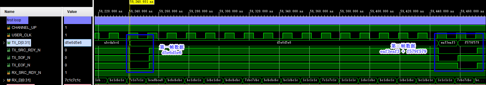
Data received by the receiving end :
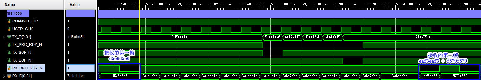
Sending and receiving are consistent , Loopback simulation is no problem .
( Two ) Simulation results of the second loop :
The data sent by the sender :
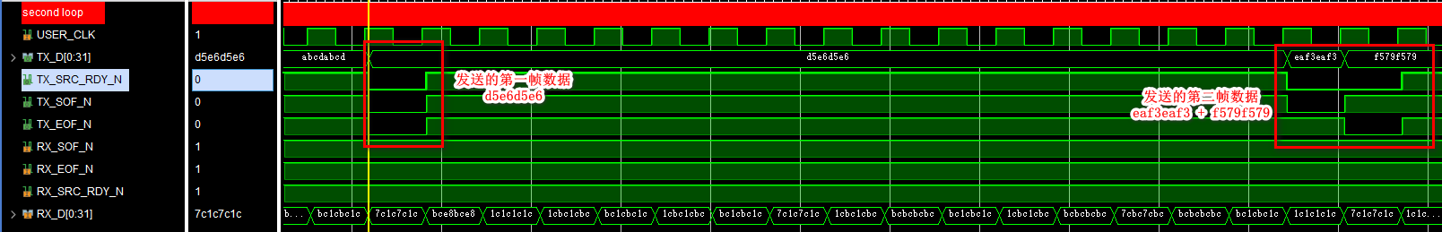
Data received by the receiving end :

Sending and receiving are consistent , Loopback simulation is no problem .
4、 summary
- You can see Aurora 8B/10B IP nucleus It's still easier to get started .
- Based on the official routine , Slightly modify the sending and receiving module , You can almost take it directly for simple use .
- Blog home page :wuzhikai.blog.csdn.net
- This paper is written by Lonely single blade original , First appeared in CSDN platform
- Do you have any questions , You can communicate with me in the comment area !
- It's not easy to create , Your support is the biggest driving force for me to continuously update ! If this article helps you , Please give me more praise 、 Reviews and collections !
边栏推荐
- Global and Chinese market of X-ray detectors 2022-2028: Research Report on technology, participants, trends, market size and share
- Kotlin basic learning 16
- Uniapp uses canvas to generate posters and save them locally
- Basic syntax of unity script (7) - member variables and instantiation
- ORA-01547、ORA-01194、ORA-01110
- Kotlin基础学习 14
- How to establish its own NFT market platform in 2022
- Kotlin基础学习 17
- Intersection vengraph
- 高性能 低功耗Cortex-A53核心板 | i.MX8M Mini
猜你喜欢

One of the future trends of SAP ui5: embrace typescript
Sentry experience and architecture, a fledgling monitoring product with a market value of $100million
MySQL index, transaction and storage engine
In the era of programmers' introspection, five-year-old programmers are afraid to go out for interviews

Basic syntax of unity script (6) - specific folder

Review materials of project management PMP high frequency examination sites (8-1)
SAML2.0 notes (I)
![[C Advanced] brother Peng takes you to play with strings and memory functions](/img/95/ab1bb0b3fa0b99e32233a5ca5d42a4.jpg)
[C Advanced] brother Peng takes you to play with strings and memory functions
![[yolo3d]: real time detection of end-to-end 3D point cloud input](/img/5e/f17960d302f663db75ad82ae0fd70f.jpg)
[yolo3d]: real time detection of end-to-end 3D point cloud input

MSI announced that its motherboard products will cancel all paper accessories
随机推荐
Basic syntax of unity script (6) - specific folder
Use blocking or non blocking for streamline
aaaaaaaaaaaaa
Global and Chinese market of autotransfusion bags 2022-2028: Research Report on technology, participants, trends, market size and share
Detailed explanation of ThreadLocal
Xlwings drawing
uniapp 使用canvas 生成海报并保存到本地
Unity脚本的基础语法(8)-协同程序与销毁方法
Kotlin基础学习 15
【DesignMode】原型模式(prototype pattern)
Custom classloader that breaks parental delegation
[yolo3d]: real time detection of end-to-end 3D point cloud input
Docker安装canal、mysql进行简单测试与实现redis和mysql缓存一致性
[HCIA continuous update] working principle of OSPF Protocol
JS generate random numbers
焱融看 | 混合云时代下,如何制定多云策略
Discrimination between sap Hana, s/4hana and SAP BTP
[HCIA continuous update] overview of dynamic routing protocol
[designmode] builder model
Pointer array & array pointer