当前位置:网站首页>Part VI, STM32 pulse width modulation (PWM) programming
Part VI, STM32 pulse width modulation (PWM) programming
2022-07-07 00:56:00 【Heavy vehicle water】
1.PWM Concept
PWM It's called pulse width modulation (Pulse Width Modulation), The frequency and duty cycle of the output square wave are controlled by programming ( Proportion of high and low levels ), Widely used in measurement , signal communication , Power control and other fields ( Breathing lights , The motor ).

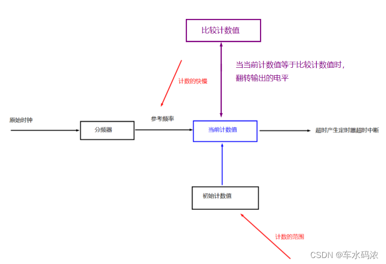
PWM Driven by timer ,PWM The period is the period of the timer , To adjust the duty cycle , You need to add a comparison counter to the timer , Simultaneous need GPIO Output waveform .
——————————————————————————————————————————
2.stm32 Medium PWM
stm32 Medium PWM It belongs to timer function , By configuring the timer, you can use PWM, In addition to the basic configuration of timer , Also add a time to compare the count value to determine the turning level , It also needs to be GPIO Multiplexing function output of PWM.
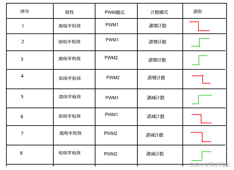
stm32 in PWM The order of high and low levels is determined by polarity ,PWM Mode and counting mode jointly determine . Polarity determines the default level ( Effective level ),PWM Mode refers to the order of effective level and invalid level in a cycle .

—————————————————————————————————————————
3. Use library functions to realize PWM To configure D1 For breathing lights
(1) Turn on the clock
GPIOF The clock TIM14 The clock , Function omitted
(2) initialization GPIO For reuse functions
GPIO_InitStruct.GPIO_Mode = GPIO_Mode_AF; GPIO_Init(...); Function omitted
(3) Set the timer 14 passageway 1 The reuse function of maps to PF9
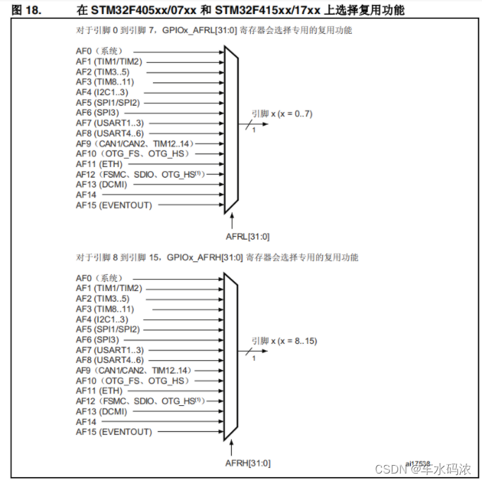
void GPIO_PinAFConfig(GPIO_TypeDef* GPIOx, uint16_t GPIO_PinSource, uint8_t GPIO_AF); Parameters : GPIOx - Which group GPIO
GPIO_PinSource - Which one? GPIO Pin
GPIO_AF - Which reuse function ( Only the reusable functions that can be mapped )
(4) Initialize the timer
TIM_TimeBaseInit(......); Function omitted
(5) initialization PWM
void TIM_OC1Init(TIM_TypeDef* TIMx, TIM_OCInitTypeDef* TIM_OCInitStruct);
Parameters : TIMx - Which timer
TIM_OCInitStruct - Initialization structure t
ypedef struct {
uint16_t TIM_OCMode; /*!< PWM Pattern @ref TIM_Output_Compare_and_PWM_modes */ uint16_t TIM_OutputState; /*!< Output status enable @ref TIM_Output_Compare_State */ uint16_t TIM_OutputNState; /*!< Ignore only for TIM1 and TIM8. */
uint32_t TIM_Pulse; /*!< Compare the count 0x0000 and 0xFFFF */
uint16_t TIM_OCPolarity; /*!< Polarity @ref TIM_Output_Compare_Polarity */ uint16_t TIM_OCNPolarity; /*!< Ignore only for TIM1 and TIM8. */ uint16_t TIM_OCIdleState; /*!< Ignore only for TIM1 and TIM8. */ uint16_t TIM_OCNIdleState; /*!< Ignore only for TIM1 and TIM8. */ } TIM_OCInitTypeDef;
(6) Can make PWM Preloading and reloading functions of
TIM_OC1PreloadConfig(TIM14, TIM_OCPreload_Enable); TIM_ARRPreloadConfig(TIM14, ENABLE);
(7) Start timer
TIM_Cmd(...); // Advanced timer (TIM1/TIM8), You also need to turn on another switch void TIM_CtrlPWMOutputs(TIM_TypeDef* TIMx, FunctionalState NewState);
Parameters : TIMx - Which timer
NewState - ENABLE/DISABLE
(8) The duty cycle can be adjusted during operation
void TIM_SetCompare1(TIM_TypeDef* TIMx, uint32_t Compare1); Parameters : TIMx - Which timer Compare1 - New comparison value
__________________________________________________________________________________________________________________________________________________________
Use library functions to configure GPIOF,TIM14, bring D1 Light breathing flickers , The code implementation is as follows :
pwm.c
#include <stm32f4xx.h>
#include <pwm.h>

void timer14_pwm_init(void)
{
	GPIO_InitTypeDef GPIO_InitStruct;
	TIM_TimeBaseInitTypeDef TIM_TimeBaseInitStruct;
	TIM_OCInitTypeDef TIM_OCInitStruct;

	//1. Turn on GPIOF and TIM14 The clock
	RCC_AHB1PeriphClockCmd(RCC_AHB1Periph_GPIOF,ENABLE);
	RCC_APB1PeriphClockCmd(RCC_APB1Periph_TIM14,ENABLE);

	//2. initialization PF9 For reuse functions
	GPIO_InitStruct.GPIO_Mode = GPIO_Mode_AF;// Reuse mode
	GPIO_InitStruct.GPIO_OType = GPIO_OType_PP;// Push pull output
	GPIO_InitStruct.GPIO_Speed = GPIO_Speed_50MHz;// High speed
	GPIO_InitStruct.GPIO_PuPd = GPIO_PuPd_NOPULL;// No up and down
	GPIO_InitStruct.GPIO_Pin = GPIO_Pin_9;//PF9
	GPIO_Init(GPIOF,&GPIO_InitStruct);

	//3. take PF9 Reuse mapping to TIM14
	GPIO_PinAFConfig(GPIOF,GPIO_PinSource9,GPIO_AF_TIM14);

	//4. Initialize the timer 14 84M / 84 = 1MHz 1M ------ 1000 ----- 1ms
	TIM_TimeBaseInitStruct.TIM_Prescaler = 84-1;// The prescaled coefficients
	TIM_TimeBaseInitStruct.TIM_Period = 1000-1;// Initial count
	TIM_TimeBaseInitStruct.TIM_CounterMode = TIM_CounterMode_Down;// Count down
	TIM_TimeBaseInitStruct.TIM_ClockDivision = TIM_CKD_DIV1;// Clock factor
	TIM_TimeBaseInit(TIM14,&TIM_TimeBaseInitStruct);

	//5.PWM initialization
	TIM_OCInitStruct.TIM_OCMode = TIM_OCMode_PWM1;//PWM Pattern 1
	TIM_OCInitStruct.TIM_OCPolarity = TIM_OCPolarity_Low;// Low level active
	TIM_OCInitStruct.TIM_OutputState = TIM_OutputState_Enable;// Can make
	TIM_OCInitStruct.TIM_Pulse = 800;// Compare the count
	TIM_OC1Init(TIM14,&TIM_OCInitStruct);

	//6. Can make PWM Preloading and reloading functions of
	TIM_OC1PreloadConfig(TIM14, TIM_OCPreload_Enable);
	TIM_ARRPreloadConfig(TIM14, ENABLE);

	//7. Enable timer 14
	TIM_Cmd(TIM14,ENABLE);
}
pwm.h
#ifndef _KEY_H_
#define _KEY_H_

#define S1 PAin(0)
#define S2 PEin(2)
#define S3 PEin(3)
#define S4 PEin(4)

void key_init(void);

#endif
The main function main.c
#include <stm32f4xx.h>
#include <includes.h>

int main()
{
	u32 comp = 0;

	//1. Interrupt priority grouping  2:2
	NVIC_PriorityGroupConfig(NVIC_PriorityGroup_2);

	// initialization
	//led_init();
	//key_init();
	beep_init();
	exti_init();
	mq2_init();
	delay_init();
	//timer2_init();
	//timer10_init();
	timer14_pwm_init();

	//D1 For breathing lights
	while(1){
		//1s From darkest to brightest
		while(comp<1000){
			TIM_SetCompare1(TIM14,comp);
			comp++;
			delay_ms(1);
		}

		//1s From brightest to darkest
		while(comp>0){
			TIM_SetCompare1(TIM14,comp);
			comp--;
			delay_ms(1);
		}

		delay_ms(200);
	}

}
practice :
Use TIM1 The passage of 4 control D4 As a breathing lamp
TIM1 It's the advanced timer passageway 4
边栏推荐
- Equals() and hashcode()
- Chapter II proxy and cookies of urllib Library
- How do novices get started and learn PostgreSQL?
- Linear algebra of deep learning
- Idea automatically imports and deletes package settings
- 【批处理DOS-CMD命令-汇总和小结】-跳转、循环、条件命令(goto、errorlevel、if、for[读取、切分、提取字符串]、)cmd命令错误汇总,cmd错误
- Js+svg love diffusion animation JS special effects
- ActiveReportsJS 3.1中文版|||ActiveReportsJS 3.1英文版
- Mujoco produces analog video
- Learn to use code to generate beautiful interface documents!!!
猜你喜欢
《安富莱嵌入式周报》第272期:2022.06.27--2022.07.03

迈动互联中标北京人寿保险,助推客户提升品牌价值
![[Niuke classic question 01] bit operation](/img/f7/e3a482c379ec9bbdb453a05e5e08cb.jpg)
[Niuke classic question 01] bit operation
第五篇,STM32系统定时器和通用定时器编程

equals()与hashCode()
Summary of being a microservice R & D Engineer in the past year

Dell Notebook Periodic Flash Screen Fault

重上吹麻滩——段芝堂创始人翟立冬游记
深度学习之数据处理
Slam d'attention: un slam visuel monoculaire appris de l'attention humaine
随机推荐
QT tutorial: creating the first QT program
用tkinter做一个简单图形界面
[yolov5 6.0 | 6.1 deploy tensorrt to torch serve] environment construction | model transformation | engine model deployment (detailed packet file writing method)
5种不同的代码相似性检测,以及代码相似性检测的发展趋势
Dell笔记本周期性闪屏故障
Attention SLAM:一種從人類注意中學習的視覺單目SLAM
Advanced learning of MySQL -- basics -- multi table query -- self join
[C language] dynamic address book
Advanced learning of MySQL -- basics -- basic operation of transactions
How do novices get started and learn PostgreSQL?
Markov decision process
【批处理DOS-CMD命令-汇总和小结】-字符串搜索、查找、筛选命令(find、findstr),Find和findstr的区别和辨析
第五篇,STM32系统定时器和通用定时器编程
Cross-entrpy Method
Memory optimization of Amazon memorydb for redis and Amazon elasticache for redis
dynamic programming
Deeply explore the compilation and pile insertion technology (IV. ASM exploration)
Set (generic & list & Set & custom sort)
C9高校,博士生一作发Nature!
深度学习之数据处理
