当前位置:网站首页>Part V: STM32 system timer and general timer programming
Part V: STM32 system timer and general timer programming
2022-07-07 00:56:00 【Heavy vehicle water】
1. Timer concept
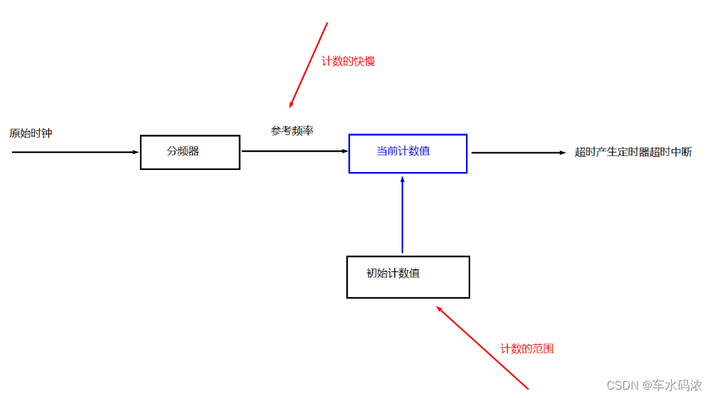
Timer is essentially a counter , Count from a certain value , When the count value reaches a certain value, the timing time is . The timing time is determined by the counting range ( Initial count ) And the speed of counting ( Current count ) To decide .
Use a timer to make a delay or heartbeat clock , The main steps include starting , Determine the reference clock frequency , Determine the initial count , Query timeout flag , As shown in the figure below .
———————————————————————————————————————————
2.systick ---------------------- System timer
systick It's a simple timer , Belong to ARM nucleus , It is often used for precise delay , It can also be used as the system heartbeat clock .
(1)cortex-M4 System timer of kernel ( Refer to authoritative guidelines 9.5 section )
systick Is a count down ,24 position (0xffffff), With automatic reload function ( After a fixed time , Automatically write an initial count value , There is no need for developers to re initialize the assignment ) Simple timer . The clock source is provided externally , You can choose 8 Frequency division AHB The clock (21MHz) perhaps HCLK(168MHz).

Systick The register organization is as follows , Generally, the registers that need to be configured are control and status registers (CTRL), Reload the load value register (LOAD), Current value register (VAL) These three .


———————————————————————————————————————————
3. Use systick Achieve accurate delay
First step , Select the reference clock (21MHzAHB Clock or HLCK The clock );
The second step , Set the initial count value to determine the timer cycle ( Delay Time );
The third step , Enable timer ;
Step four , The query timeout flag waits for the delay time to .
———————————————————————————————————————————
4.Sydtick Timer code implementation
void delay_init(void)
{
// choice 21MAHB Clock as clock source
//SYSTICK Control and status register second position 0
//SysTick->CTRL &= ~(0x01<<2);
//SysTick->CTRL &= ~SysTick_CTRL_CLKSOURCE_Msk;
// Library function writing
SysTick_CLKSourceConfig(SysTick_CLKSource_HCLK_Div8);
}
// choice 21MHz, 1um=21, 1ms=21000
// Millisecond delay 1ms = 21000 n<798 ------ (2^24)/21000
void delay_ms(unsigned int nms)
{
// Calculate the initial value and put it into the initial value register , Calculate from the initial value
SysTick->LOAD = 21000*nms-1;
SysTick->VAL = 0;// The current count value is 0
// start-up systick Start timing
SysTick->CTRL |= SysTick_CTRL_ENABLE_Msk;
// The wait count is 0, Control register 16 Displacement 1
while(!(SysTick->CTRL&SysTick_CTRL_COUNTFLAG_Msk));
// close systick
SysTick->CTRL &= ~SysTick_CTRL_ENABLE_Msk;
}
——————————————————————————————————————————————————————————————————————————————————————5. Universal timer
(1) Introduce
The basic function of timer is timing , General timer belongs to peripheral , Usually used with other hardware , For example, periodically collect sensor data , periodic ADC transformation , Periodically report data , Combine the general timer with GPIO Combine to produce more functions (PWM, Pulse detection .....).
stm32f407 Yes 14 Peripheral timers ,TIM2~TIM5 TIM9~TIM14 It belongs to general timer ,TIM1 and TIM8 It belongs to advanced timer ,TIM6 and TIM7 It belongs to basic timer .
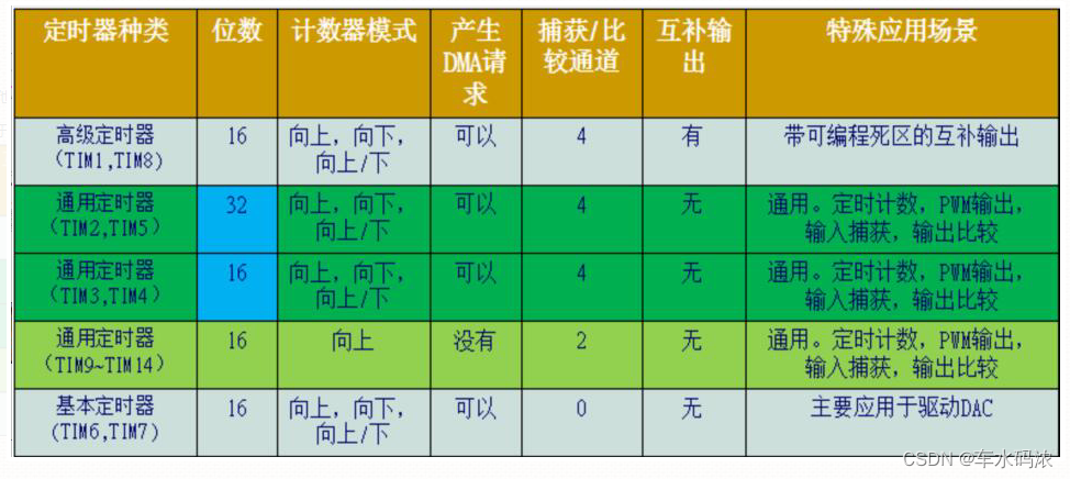
With TIM2~TIM5 For example , Understand the use of general timer
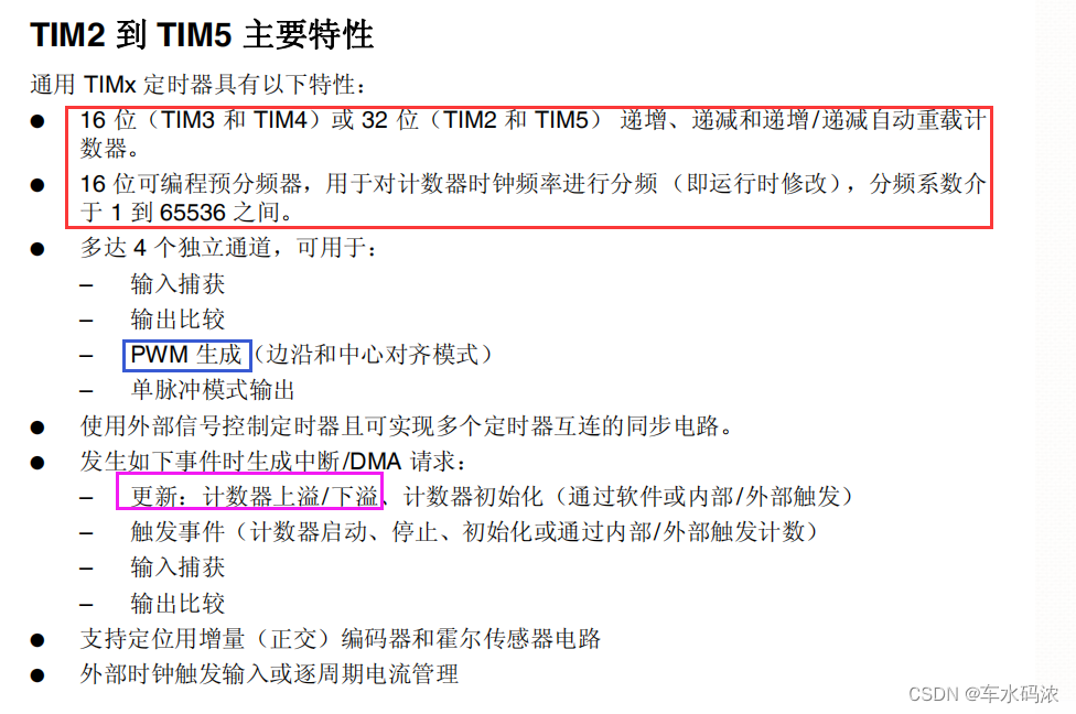
Three counting modes :
Count up ( Increasing ) 0 ~ Initial count
Count down ( Decline ) Initial count ~ 0
Two way counting ( Increasing / Decline ) Initial count ~ 0 ~ Initial count
The original clock frequency of the general timer depends on the bus and the frequency division coefficient of the bus

———————————————————————————————————————————
6. Timer (TIM2) Library function programming implementation
Add the source code of timer library function in the project
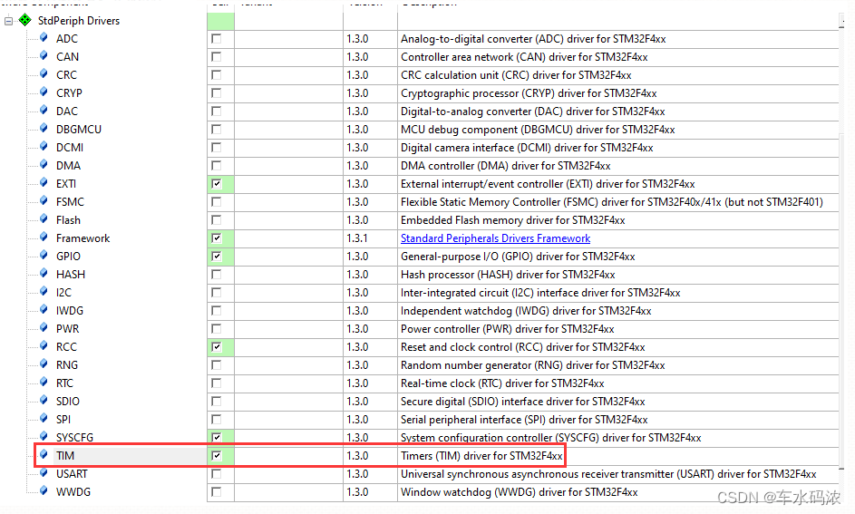
(1) Turn on timer 2 The clock of
RCC_APB1PeriphClockCmd(RCC_APB1Periph_TIM2, ENABLE);
(2) Initialize the timer
void TIM_TimeBaseInit(TIM_TypeDef* TIMx, TIM_TimeBaseInitTypeDef* TIM_TimeBaseInitStruct); Parameters : TIMx - Which timer TIM_TimeBaseInitStruct - Initialization structure typedef struct { uint16_t TIM_Prescaler; /*!< The prescaled coefficients 0x0000 and 0xFFFF */ uint16_t TIM_CounterMode; /*!< Count mode @ref TIM_Counter_Mode */ uint32_t TIM_Period; /*!< Initial count 0x0000 and 0xFFFF. */ uint16_t TIM_ClockDivision; /*!< Clock factor @ref TIM_Clock_Division_CKD */ uint8_t TIM_RepetitionCounter; /*!< Advanced timer function , Ignore */ } TIM_TimeBaseInitTypeDef;
(3) initialization NVIC
NVIC_Init(...);
(4) Enable timer interrupt
void TIM_ITConfig(TIM_TypeDef* TIMx, uint16_t TIM_IT, FunctionalState NewState); Parameters : TIMx - Which timer TIM_IT - Which interrupt TIM_IT_Update NewState - Can make / prohibit ENABLE
(5) Implement timer interrupt processing function
void TIM2_IRQHandler(void) { if(TIM_GetITStatus(TIM2, TIM_IT_Update)==SET){ //...... // Clear interrupt flag TIM_ClearITPendingBit(TIM2, TIM_IT_Update); } }
(6) Start timer
TIM_Cmd(TIM2,ENABLE);
————————————————
Copyright notice : This paper is about CSDN Blogger 「 Heavy vehicle water 」 The original article of , follow CC 4.0 BY-SA Copyright agreement , For reprint, please attach the original source link and this statement .
Link to the original text :https://blog.csdn.net/weixin_44651073/article/details/125576286
边栏推荐
- Telerik UI 2022 R2 SP1 Retail-Not Crack
- 腾讯云 WebShell 体验
- Article management system based on SSM framework
- Chapter 5 DML data operation
- Attention SLAM:一種從人類注意中學習的視覺單目SLAM
- Cross-entrpy Method
- Lombok 同时使⽤ @Data 和 @Builder 的坑,你中招没?
- The way of intelligent operation and maintenance application, bid farewell to the crisis of enterprise digital transformation
- A brief history of deep learning (I)
- 通过串口实现printf函数,中断实现串口数据接收
猜你喜欢

threejs图片变形放大全屏动画js特效
alexnet实验偶遇:loss nan, train acc 0.100, test acc 0.100情况
Part 7: STM32 serial communication programming

迈动互联中标北京人寿保险,助推客户提升品牌价值
![[software reverse automation] complete collection of reverse tools](/img/72/d3e46a820796a48b458cd2d0a18f8f.png)
[software reverse automation] complete collection of reverse tools
Learn self 3D representation like ray tracing ego3rt
Distributed cache
ActiveReportsJS 3.1中文版|||ActiveReportsJS 3.1英文版

Telerik UI 2022 R2 SP1 Retail-Not Crack
Hero League | King | cross the line of fire BGM AI score competition sharing
随机推荐
Cross-entrpy Method
ActiveReportsJS 3.1中文版|||ActiveReportsJS 3.1英文版
【YoloV5 6.0|6.1 部署 TensorRT到torchserve】环境搭建|模型转换|engine模型部署(详细的packet文件编写方法)
build. How to configure the dependent version number in the gradle file
A brief history of deep learning (I)
Use mujoco to simulate Cassie robot
5种不同的代码相似性检测,以及代码相似性检测的发展趋势
Interface master v3.9, API low code development tool, build your interface service platform immediately
[Batch dos - cmd Command - Summary and Summary] - String search, find, Filter Commands (FIND, findstr), differentiation and Analysis of Find and findstr
What kind of experience is it to realize real-time collaboration in jupyter
Common shortcuts to idea
英雄联盟|王者|穿越火线 bgm AI配乐大赛分享
第五篇,STM32系统定时器和通用定时器编程
[daily problem insight] prefix and -- count the number of fertile pyramids in the farm
Lombok 同时使⽤ @Data 和 @Builder 的坑,你中招没?
第六篇,STM32脉冲宽度调制(PWM)编程
重上吹麻滩——段芝堂创始人翟立冬游记
Summary of being a microservice R & D Engineer in the past year
再聊聊我常用的15个数据源网站
批量获取中国所有行政区域经边界纬度坐标(到县区级别)