当前位置:网站首页>Serial communication relay Modbus communication host computer debugging software tool project development case
Serial communication relay Modbus communication host computer debugging software tool project development case
2022-07-07 10:18:00 【I data acquisition IOT - Shanghai / Henan】
Project requirements analysis :
1.MODBUS Special debugging tool interface requirements :
1.1 Retain “MODBUS Debugging tools ” Select the communication port number and configuration selection function of the upper computer ;
1.2 Retain “MODBUS Debugging tools ” Sent in 、 Received message display area ;
1.3 Retain “MODBUS Debugging tools ” in 03 Instructions 、06 Instructions 、10 Command operation function .
1.4 Newly added module address reading function : Read the original address code of the target address and display it ;
1.5 Add module address modification function : Change the original address to the set target address ; And show whether it is successful .
1.6 Newly added the function of selecting communication baud rate modification : Change the target module to 9600,19200,115200 etc. ;
1.7 Four new control operation functions are added :
1) The control target address can be selected : Specify the address 1~125, Or broadcast address FF
2) Closing control of the first relay of the target address ;
3) Closing control of the second relay of the target address ;
4) Closing control of the third relay of the target address ;
5) Closing control of the fourth relay of the target address ;
1.8 Newly added control status data bit register reading and parsing function :
bit00 The first 1 Circuit relay 1- closed , It means work ;0- To break off , Indicates standby .
bit01 The first 2 Circuit relay 1- closed , It means work ;0- To break off , Indicates standby .
bit02 The first 3 Circuit relay 1- closed , It means work ;0- To break off , Indicates standby .
bit03 The first 4 Circuit relay 1- closed , It means work ;0- To break off , Indicates standby .
2. Communication register definition
Register number Sender name Access type Data value range
Decimal system Hexadecimal code
0 0
1 1 Control data R/W The data is A5 when : Control relay No 1 Luhe , The first 2,3 Lu Fen ;
The data is B5 when : Control relay No 2 Luhe , The first 1,3 Lu Fen ;
The data is C5 when : Control relay No 3 Luhe , The first 1,2 Lu Fen ;
The data is FA when : downtime , Control relay No 1,2,3,4 Lu Fen ;
2 2 Control state R Please refer to 《 Terminal control status data bit definition 》
3 3 spare R
4 4 mailing address R/W
5 5 Communication baud rate R/W
… … spare R
Terminal control status data bit definition
bit00 The first 1 Circuit relay 1- closed , It means work ;0- To break off , Indicates standby .
bit01 The first 2 Circuit relay 1- closed , It means work ;0- To break off , Indicates standby .
bit02 The first 3 Circuit relay 1- closed , It means work ;0- To break off , Indicates standby .
bit03 The first 4 Circuit relay 1- closed , It means work ;0- To break off , Indicates standby .
bit04 Undefined , Retain Undefined , Retain
bit05 Undefined , Retain Undefined , Retain
bit06 Undefined , Retain Undefined , Retain
bit07 Undefined , Retain Undefined , Retain
3. Communication format
3.1 Physical interface
Communication mode : Serial RS232 or RS485.
Transmission rate :4800、9600、19200,115200
Character format :8 Bit data bit 、1 Bit stop bit 、( No verification / Odd check / Even check , Can be set ).
3.2 frame
3.2.1 Frame structure
The frame structure is shown in the figure , Each frame contains : Address 1BYTE, Function number 1BYTE, Information nBYTE, check 2BYTE, use MODBUS In the statute RTU The way , The communication frame is in HEX Code transmission .
Address (ADDR) Function number FC) data (DATA) check (CRC)
3.2.2 Address (ADDR)
Refers to MODBUS mailing address , The scope is 1-254 Can be set .
3.2.3 Function number
The command code sent to the lower computer .
3.2.4 data
The downlink command frame is the additional information of the command , The uplink response frame is the response data .
3.2.5 check
use CRC check .
3.3 Command interpretation
All commands must be issued in strict accordance with the format given below , If the setting is successful, the monitoring device will respond in response format , Otherwise, the monitoring device will not respond .– Means to fill in according to the actual value .
3.3.1 Read command
03H command 03H Command response
Device address code – Device address code –
Function code 03H function 03H
High byte of starting address – Number of bytes –
Low byte of starting address – data 0 Hi byte –
Number of registers high byte – data 0 Lo Low byte –
Low number of registers – : :
CRC Check code high byte – data N Hi byte –
CRC Check code low byte – data N Lo Low byte –
CRC Check code high byte –
CRC Check code low byte –
give an example : Request to read register 108-110 Example
request Respond to
Device address code 01 Device address code 01
Function code 03 function 03
High byte of starting address 00 Number of bytes 06
Low byte of starting address 6B Register values Hi(108) 02
Number of registers high byte 00 Register values LO(108) 2B
Low number of registers 03 Register values Hi(109) 00
CRC Check code high byte 74 Register values LO(109) 00
CRC Check code low byte 17 Register values Hi(110) 00
Register values LO(110) 64
CRC Hi 05
CRC Lo 7A
3.3.2 Write orders
06H command 06H Command response
Device address code – Slave Address –
Function code 06H Function Code 06H
Register address high byte – Reg. Hi –
Low byte of starting address – Reg. Lo –
data Hi High byte – Data Hi –
data Lo Low byte – Data Lo –
CRC Check code high byte – CRC Hi –
CRC Check code low byte – CRC Lo –
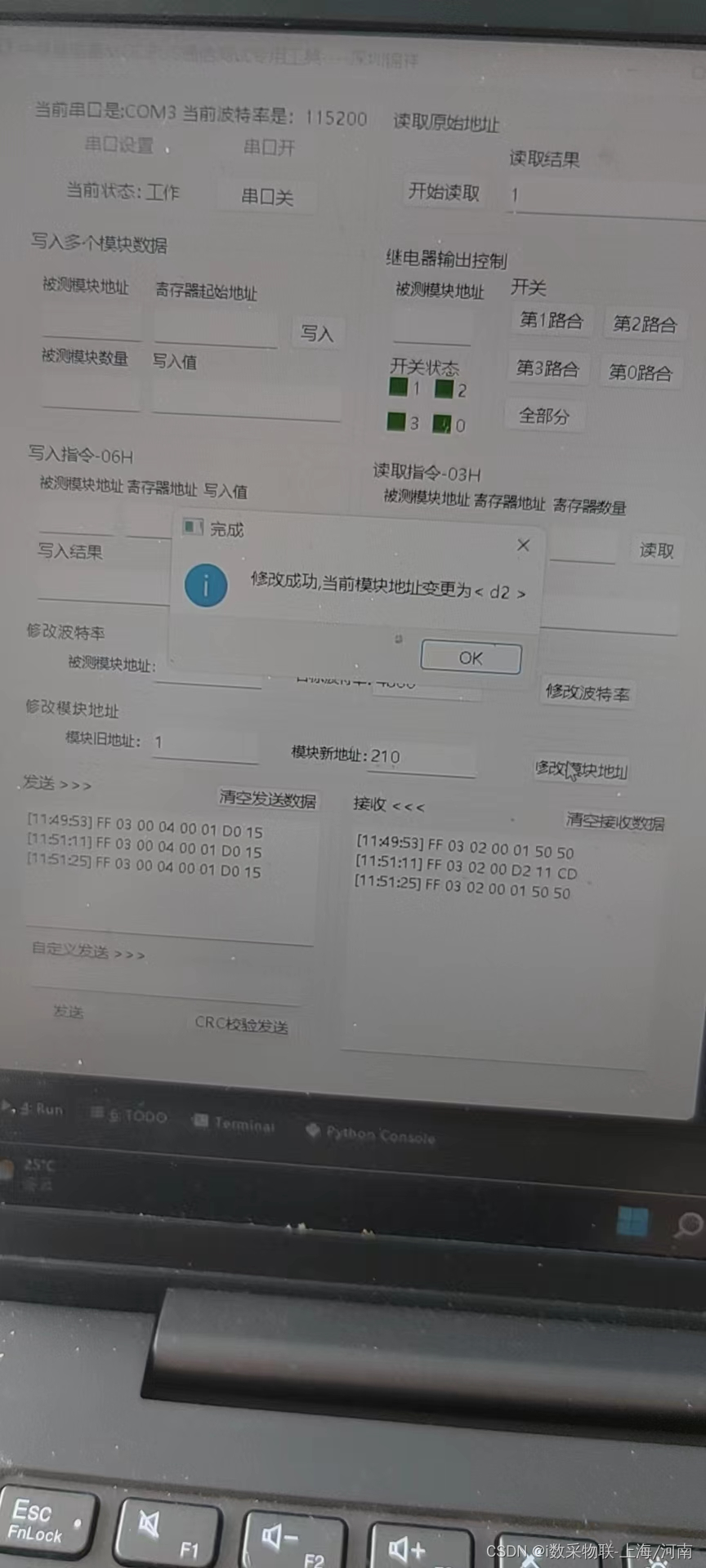
4. Communication test
4.1 Module address writing
Address range from 01~125, use 06 Command write 04 In the register ; Command format :
The original address command Register number New address Check code
XX 06 00 04 00 XX XX XX
give an example :00 06 00 04 00 01 08 1A It means that it will be 00 The address of is changed to 01;
4.2 Four control operation functions
(1) The control target address can be selected : Specify the address 1~125, Or broadcast address FF, When choosing FF when , All modules on the bus are synchronously controlled .
(2) The first relay operation of the target address module :
Module address command Register number Relay control data Check code
XX 06 00 01 00 A5 XX XX
(3) Specify the second relay operation of the address module :
Module address command Register number Relay control data Check code
XX 06 00 01 00 B5 XX XX
(4) Specify the third relay operation of the address module :
Module address command Register number Relay control data Check code
XX 06 00 01 00 C5 XX XX
(5) The three-way relay of the specified address module is fully closed :
Module address command Register number Relay control data Check code
XX 06 00 01 00 FA XX XX
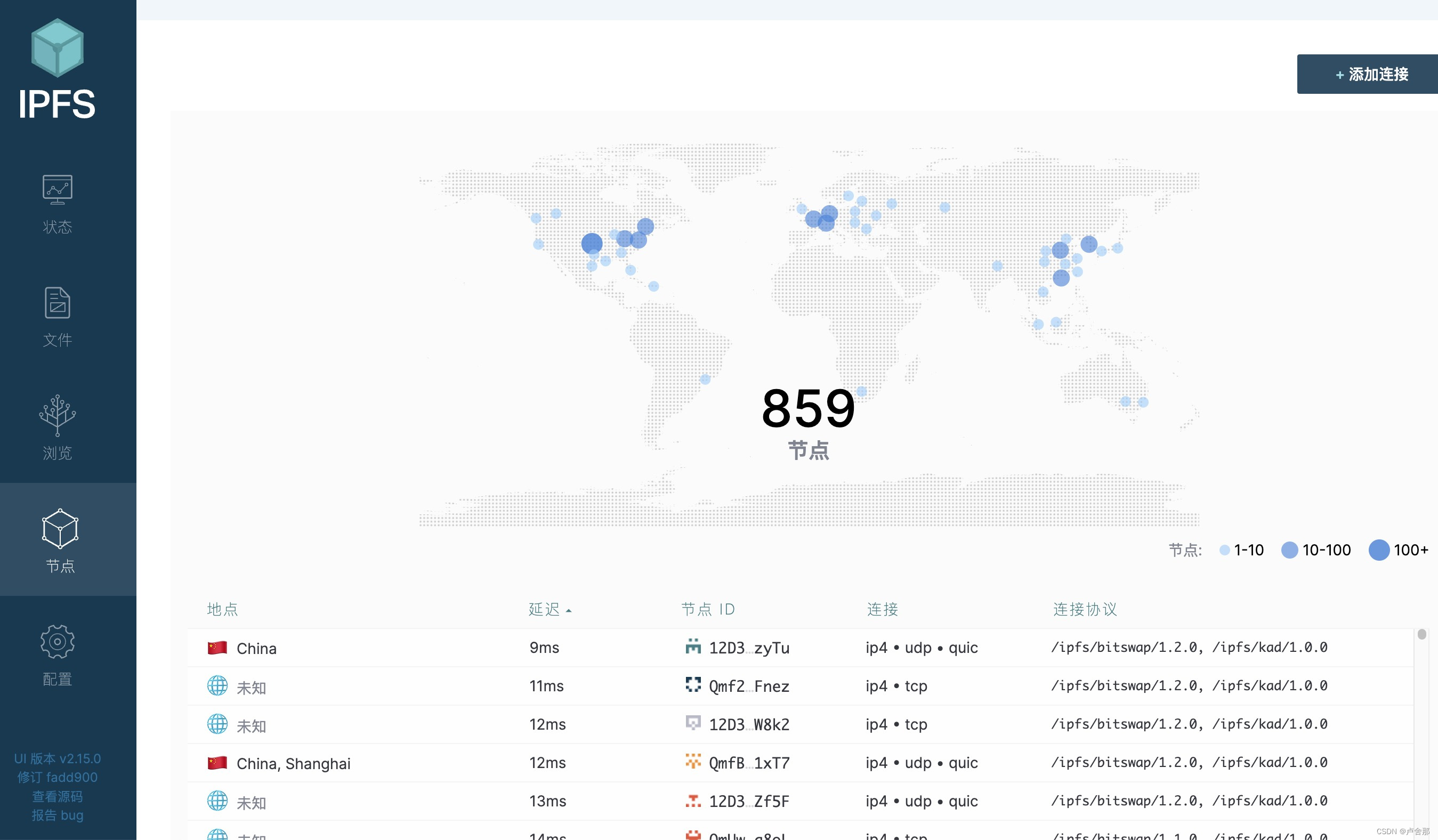
Two 、 Project development plan
Use python pyqt Framework development . Use hardware sample debugging to solve software bug problem
The software interface is as follows :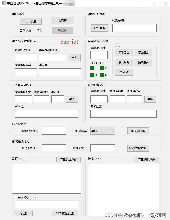
3、 ... and 、 The project is delivered to the commissioning site :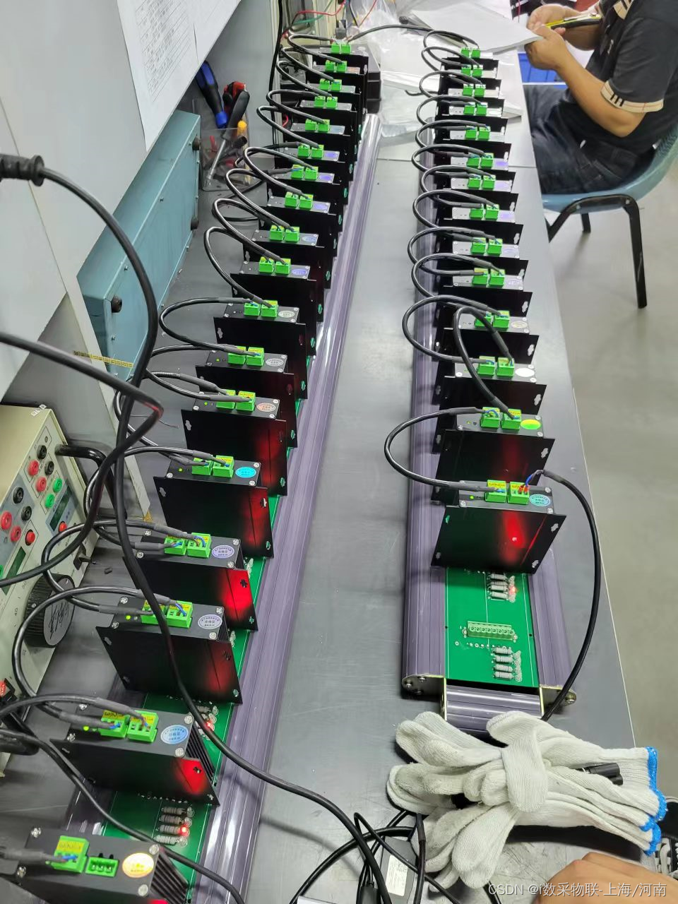
边栏推荐
- Leetcode exercise - 113 Path sum II
- Parameter sniffing (1/2)
- MCU is the most popular science (ten thousand words summary, worth collecting)
- STM32基础知识—内存映射
- 学习记录——高精度加法和乘法
- A wave of open source notebooks is coming
- Horizontal split of database
- ES6中的原型对象
- The method of word automatically generating directory
- Programming features of ISP, IAP, ICP, JTAG and SWD
猜你喜欢
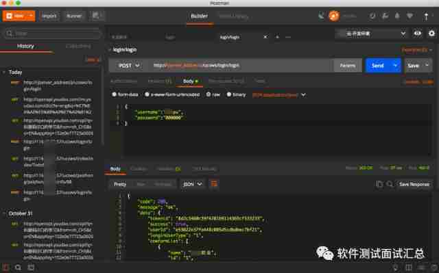
Postman interface test IV
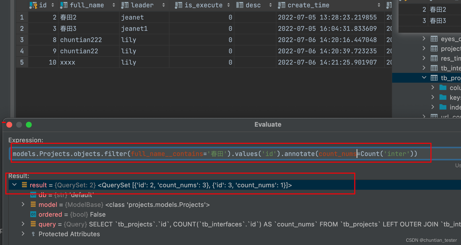
ORM -- grouping query, aggregation query, query set queryset object properties

反卷积通俗详细解析与nn.ConvTranspose2d重要参数解释
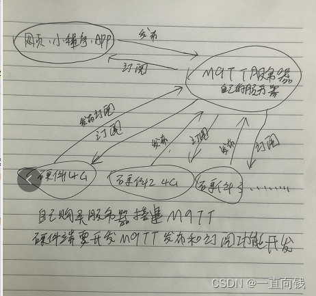
搭建物联网硬件通信技术几种方案

【剑指Offer】42. 栈的压入、弹出序列
Postman interface test V
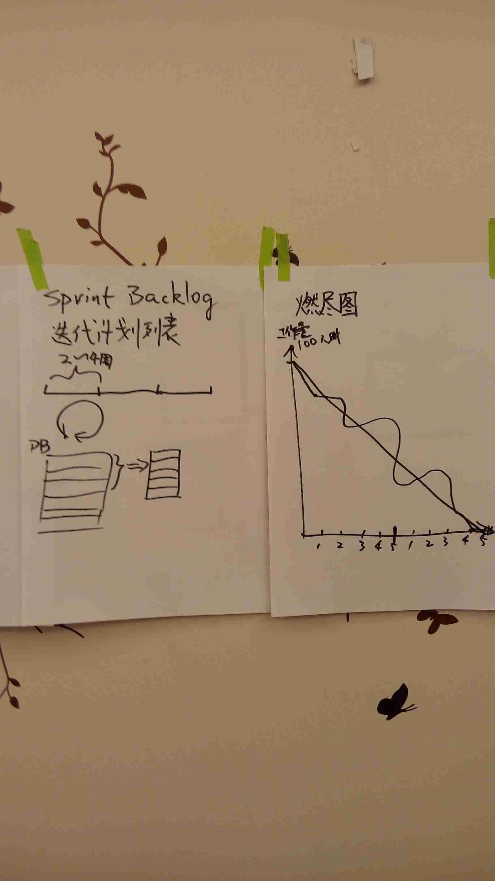
Agile course training
web3.0系列之分布式存储IPFS
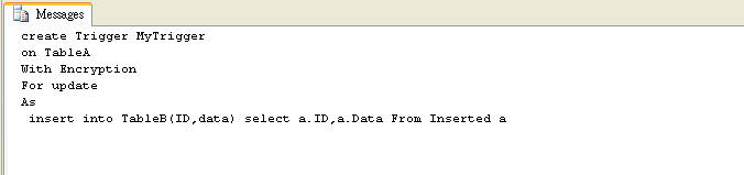
对存储过程进行加密和解密(SQL 2008/SQL 2012)

Video based full link Intelligent Cloud? This article explains in detail what Alibaba cloud video cloud "intelligent media production" is
随机推荐
. Net configuration system
MongoDB创建一个隐式数据库用作练习
Guide de signature du Code Appx
电表远程抄表拉合闸操作命令指令
Bean operation domain and life cycle
Win10安装VS2015
ORM模型--数据记录的创建操作,查询操作
Three years after graduation
Interface test
CONDA creates virtual environment offline
Factorial implementation of large integer classes
中国首款电音音频类“山野电音”数藏发售来了!
Deconvolution popular detailed analysis and nn Convtranspose2d important parameter interpretation
ISP、IAP、ICP、JTAG、SWD的编程特点
Programming features of ISP, IAP, ICP, JTAG and SWD
Encrypt and decrypt stored procedures (SQL 2008/sql 2012)
Google colab loads Google drive (Google drive is used in Google colab)
大整数类实现阶乘
[learning notes - Li Hongyi] Gan (generation of confrontation network) full series (I)
网上可以开炒股账户吗安全吗