当前位置:网站首页>Introduction to GPIO
Introduction to GPIO
2022-07-06 23:55:00 【Xiao Hou_ two thousand and twenty-two】
GPIO brief introduction
1. Introduce
GPIO Is the abbreviation of general input and output port , In a nutshell STM32 Controllable pins ,STM32 Chip GPIO Pins are connected to external devices , So as to realize external communication 、 Control and data acquisition functions .STM32 Chip GPIO Divided into many groups , Each group has 16 One pin , If the model is STM32F103VET6 The models of chips have GPIOA、GPIOB、GPIOC to GPIOE common 5 Group GPIO, The chip is a total of 1O0 One pin , among GPIO It's a big part of it , be-all GPIO All pins have basic input and output functions .
The most basic output function is made up of STM32 Control pin output high 、 Low level , Switch control is realized , If you put GPIO Pin into LED The lamp , Then you can control LED The light goes on and off , Pin into relay or triode , Then you can control the on-off of external high-power circuits through relays or triodes .
The most basic input function is to detect the external input level , If you put GPIO Pin to key , Distinguish whether the key is pressed by the level .
1.1 Protection diode and upper 、 Pull down resistance
** The two protection diodes of the pin can prevent too high or too low voltage input outside the pin ,** When the pin voltage is higher than VDD when , The diode above is on , When the pin voltage is below Vss when , The diode below is on , Prevent abnormal voltage from being introduced into the chip and causing the chip to burn . Despite this protection , It doesn't mean that STM32 The pin can be directly connected to the high power driver , Such as direct drive motor , Forced drive or the motor doesn't work , Or cause the chip to burn out , It is necessary to increase the power and isolate the circuit drive .
1.2 P-MOS Tube and N-MOS tube
GPIO The pin line passes through two protection diodes , Up to “ The input mode ” structure , Down to “ The output mode ” structure . Let's look at the output mode section first , The line goes through a road made up of PMOS and N-MOS A cell circuit made up of tubes . This structure makes GPIO Possess “ Push pull output ” and “ Open drain output ” Two modes .
So-called Push pull output mode , It's based on these two MOS Named after the way the tube works .** In this structure, high level is input , After the reverse , At the top of the P-MOS Conduction , At the bottom of the N-MOS close , External output high level ; In this structure, low level is input , After the reverse ,N-MOS The pipe is open ,P-MOS close , External output low level .***** When the pin level switches between high and low , Two pipes turn on ,P The tube is responsible for filling the current ,N The tube is responsible for pulling the current , The load capacity and switching speed are greatly improved compared with ordinary methods .* The low level of push-pull output is 0 v , The high level is 3.3 v , Refer to figure push-pull equivalent circuit for details , It is the equivalent circuit of push-pull output mode .
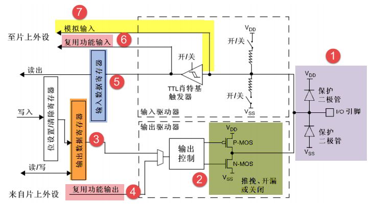
And in the Open drain output mode when , At the top of the P-MOS It doesn't work at all . If we control the output to be 0, Low level , be PMOS The tube is closed ,N-MOS The pipe is open , Ground the output , If the control output is 1( It can't directly output high level ) when , be P-MOS Tube and N-MOS All the tubes are closed , So the pin neither outputs high level , It doesn't output low level either , It's a high resistance state .
Open drain output is generally used in I2C、SMBUS Communication, etc “ Line and ” Function of the bus circuit
typedef enum
 {

     GPIO_Mode_AIN = 0x0, //  Analog input
     GPIO_Mode_IN_FLOATING = 0x04, //  Floating input
     GPIO_Mode_IPD = 0x28, //  Drop down input
     GPIO_Mode_IPU = 0x48, //  Pull up input

     GPIO_Mode_Out_OD = 0x14, //  Open drain output
     GPIO_Mode_Out_PP = 0x10, //  Push pull output
     GPIO_Mode_AF_OD = 0x1C, //  Reuse open drain output
     GPIO_Mode_AF_PP = 0x18 //  Multiplexing push pull output
 } GPIOMode_TypeDef;
1.3 Lighten up LED The lamp
technological process
1) Can make IO Port clock , By calling :
RCC_ABP2PeriphColckCmd( )
- initialization IO Mouth mode , call :
GPIO_Init( )
- operation IO mouth , Output high and low level
GPIO_SetBits( )
GPIO_ResetBits( )
# In order to increase the portability of the code , Define hardware related macros in  bsp_LED.h  in
#ifndef _BSP_LED_H
#define _BSP_LED_H

#define LED1_GPIO_CLK RCC_APB2Periph_GPIOA
#define LED1_GPIO_PORT GPIOA
#define LED1_GPIO_PIN GPIO_Pin_8

#define LED2_GPIO_CLK RCC_APB2Periph_GPIOD
#define LED2_GPIO_PORT GPIOD
#define LED2_GPIO_PIN GPIO_Pin_2

#include "stm32f10x.h"
void LED_GPIO_Config(void);
#endif/*_BSP_LED_H*/
LED Initialize configuration
#include "./LED/bsp_led.h"
void LED_GPIO_Config(void)
{

	GPIO_InitTypeDef GPIO_InitType_struct_A;
	GPIO_InitTypeDef GPIO_InitType_struct_D;

	/* Step 1 turn on the peripheral clock */
	RCC_APB2PeriphClockCmd(LED1_GPIO_CLK,ENABLE);
	RCC_APB2PeriphClockCmd(LED2_GPIO_CLK,ENABLE);
	/* The second step is to configure the peripheral initialization structure */
	GPIO_InitType_struct_A.GPIO_Pin = LED1_GPIO_PIN;
	GPIO_InitType_struct_A.GPIO_Mode = GPIO_Mode_Out_PP;
	GPIO_InitType_struct_A.GPIO_Speed = GPIO_Speed_10MHz;

	GPIO_InitType_struct_D.GPIO_Pin = LED2_GPIO_PIN;
	GPIO_InitType_struct_D.GPIO_Mode = GPIO_Mode_Out_PP;
	GPIO_InitType_struct_D.GPIO_Speed = GPIO_Speed_10MHz;

	/* Step 3 call the initialization function , Write the configured structure members to the register */
	GPIO_Init(LED1_GPIO_PORT,&GPIO_InitType_struct_A);
	GPIO_Init(LED2_GPIO_PORT,&GPIO_InitType_struct_D);
The main program
#include "stm32f10x.h"
#include "./LED/bsp_led.h"

void delay(uint32_t count)
{

	for(;count!=0;count--);
}

int main(void)
{

	LED_GPIO_Config( );

	while(1)
	{

		GPIO_SetBits(LED2_GPIO_PORT,LED2_GPIO_PIN);
		GPIO_ResetBits(LED1_GPIO_PORT,LED1_GPIO_PIN);
		delay(0xfffff);
		GPIO_SetBits(LED1_GPIO_PORT,LED1_GPIO_PIN);
		GPIO_ResetBits(GPIOD,LED2_GPIO_PIN);
		delay(0xfffff);

	}
}
边栏推荐
- Oracle EMCC 13.5 environment in docker every minute
- Close unregistering application XXX with Eureka with status down after Eureka client starts
- DAY FOUR
- 《LaTex》LaTex数学公式简介「建议收藏」
- 【212】php发送post请求有哪三种方法
- PDF文档签名指南
- Laravel8 uses passport authentication to log in and generate a token
- MySQL master-slave multi-source replication (3 master and 1 slave) setup and synchronization test
- leetcode:236. 二叉树的最近公共祖先
- pinia 模块划分
猜你喜欢
Close unregistering application XXX with Eureka with status down after Eureka client starts
达晨史上最大单笔投资,今天IPO了
The best sister won the big factory offer of 8 test posts at one go, which made me very proud
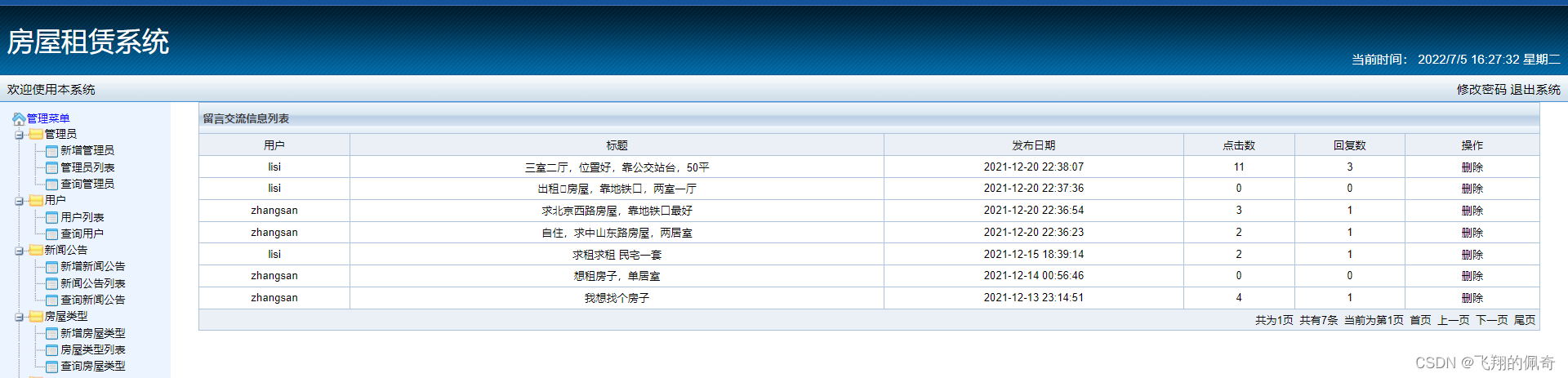
Building lease management system based on SSM framework

11 preparations for Web3 and Decentralization for traditional enterprises
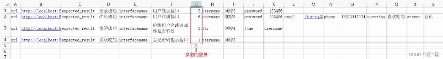
Interface joint debugging test script optimization v4.0
DAY FOUR
![[boutique] Pinia Persistence Based on the plug-in Pinia plugin persist](/img/53/95ab85bfd99d943f98881596d0aa8c.png)
[boutique] Pinia Persistence Based on the plug-in Pinia plugin persist
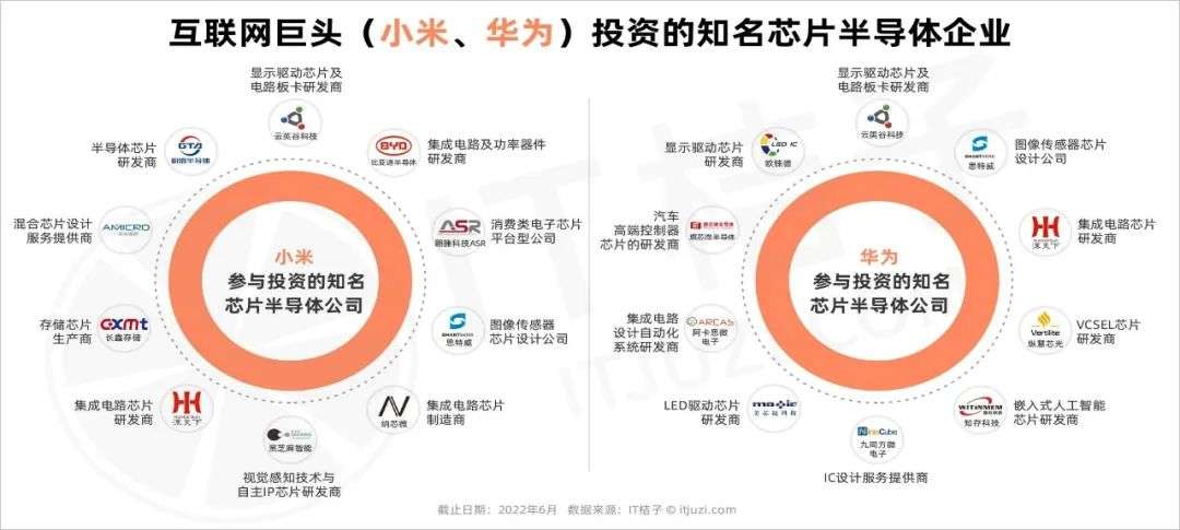
每年 2000 亿投资进入芯片领域,「中国芯」创投正蓬勃

英国都在试行4天工作制了,为什么BAT还对996上瘾?
随机推荐
openresty ngx_ Lua subrequest
Yaduo Sangu IPO
基于SSM框架实现的房屋租赁管理系统
17、 MySQL - high availability + read / write separation + gtid + semi synchronous master-slave replication cluster
在Docker中分分钟拥有Oracle EMCC 13.5环境
《LaTex》LaTex数学公式简介「建议收藏」
Oracle中使用包FY_Recover_Data.pck来恢复truncate误操作的表
DAY THREE
The programmer refused the offer because of low salary, HR became angry and netizens exploded
编译logisim
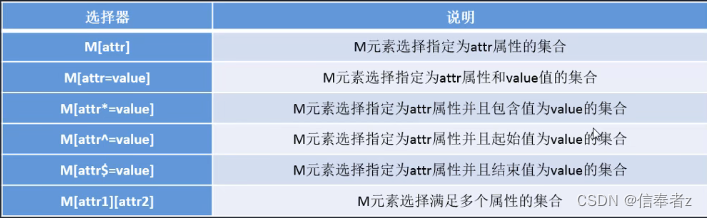
Penetration test --- database security: detailed explanation of SQL injection into database principle
基于jsp+servlet+mysql框架的旅游管理系统【源码+数据库+报告】
设计一个抢红包系统
Asset security issues or constraints on the development of the encryption industry, risk control + compliance has become the key to breaking the platform
本地部署 zeppelin 0.10.1
Pdf document signature Guide
量子时代计算机怎么保证数据安全?美国公布四项备选加密算法
Supersocket 1.6 creates a simple socket server with message length in the header
PDF文档签名指南
Wu Enda 2022 machine learning course evaluation is coming!