当前位置:网站首页>Talk about SOC startup (x) kernel startup pilot knowledge
Talk about SOC startup (x) kernel startup pilot knowledge
2022-07-07 11:27:00 【lgjjeff】
This paper is based on the following software and hardware assumptions :
framework :AARCH64
Kernel version :5.14.0-rc5
1 Question elicitation
After a long journey, I finally entered the kernel gate , Now the kernel will happily execute from the first instruction . But before starting the kernel journey , It is still necessary to look at the state of the system before entering the kernel . We know uboot The last step is to copy the kernel to memory , And will cpu Set to the following status :
(1)MMU In the off state
(2) data cache In the off state , Instructions cache It can be closed or open
(3) take dtb To the address of x0 In the register
(4) adopt armv8_switch_to_el2 The function jumps to the kernel entry address for execution
Because the page table has not been established when entering the kernel , At this time, the system is running in real mode , And ARM8 data cache The opening of depends on MMU, So obviously you need to shut down before starting the kernel MMU And data cache.
We know armv8 There are four exception levels , Under normal circumstances, the kernel should run in EL1, But because of ARMv8 Support virtualization . about type 2 hypervisor, Its guest OS Running on the EL1, if host OS It also runs in EL1, Then its architecture is as follows :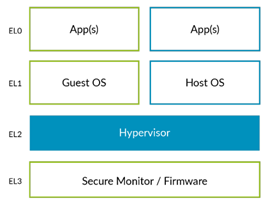
here host os And guest os All running in EL1, and hypervisor As host os Part of it runs in EL2, because host os And hypervisor Run at different exception levels , They need to interact with each other through exceptions . This requires abnormal level switching , And context saving and recovery , Obviously, it will bring relatively large expenses . To improve the efficiency of virtualization ,arm stay armv8.1 The following architecture adds a pair of vhe Support for , With permission host os Running on the EL2. At this point, the system architecture will change to the following :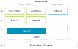
because host os And hypervisor All running in EL2, Therefore, the above expenses are reduced . however host os Itself and ordinary os There is no difference , By default, it is designed to work on EL1 in , If it passes sctlr_el1 Access system control registers , adopt vbar_el1 Access vector table base address register, etc . if host os Running on the EL2, You need to redirect the access operations of these registers to their corresponding xxx_el2 register ,arm The architecture provides register redirection at the hardware level , however os We also need to make corresponding adaptation , If enabled HCR_EL2.E2H In order to open vhe Support , Can make HCR_EL2.TGE To route the original to EL1 The exception of is routed to EL2 etc. . thereafter ,host os Then the horse can run , Dancing, lighting and dancing , All operations and operations are in EL1 At the same time , There's no need to care about where you actually run EL
uboot When loading the kernel, the kernel will be copied to the low address of memory ( Such as 0x40000000), Then jump directly to the physical address to run . But in fact, the program depends on the virtual address defined in the link script , If the code is not address independent , Then the loading address must be consistent with the link address in order to operate correctly . Let's take another look arm64 Definition of kernel start address in schema linking script (arch/arm64/kernel/vmlinu.lds.S):
OUTPUT_ARCH(aarch64)
ENTRY(_text)
…
SECTIONS
{

    …
	. = KIMAGE_VADDR;

	.head.text : {

		_text = .;
		HEAD_TEXT
	}
	…
}
Kernel entry function _text The link address of is KIMAGE_VADDR, You can see from the layout of the kernel virtual address space in the following figure , The address is 0xffff80000fffffff, Clearly and uboot The loading address of is different . So in order for the kernel to boot normally , The code at the beginning of it must support the location independent feature .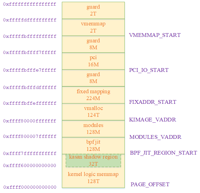
Because the location is independent, the code cannot directly access the address of the global variable , Unless the compilation phase specifies pie Options , Otherwise, there will be many limitations in coding . Therefore, the kernel naturally hopes to switch to the normal execution mode as soon as possible after startup , This requires code snippets for the kernel to run early in startup 、 Stack 、 Data segment and other parts of memory establish initialization page table , So that its running address matches the link address .
2 The exception level of kernel execution
2.1 Exception level at kernel startup
In addition to support EL0 and EL1 outside ,arm You can flexibly configure whether it supports EL2 and EL3. For the convenience of discussion , We assume that the system in question supports all EL0 – EL3 Exception level , And the starting process is bl1 -> bl2 -> bl31 -> bl32 -> uboot -> linux. The following is a typical flow chart :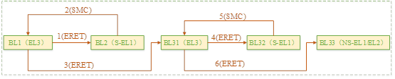
Arm Regulations cpu Start with the highest exception level supported by the system , therefore bl1 To run on EL3,Bl2 It can run on S-EL1 or EL3,BL31 You need to perform secure monitor function , Therefore, it can only run on EL3.BL32 Mainly used to support trust os, It must be implemented in S-EL1 and S-EL0 Next .
2.1.1 Uboot Execution exception level of
because uboot(bl33) from bl31 start-up , Therefore, the abnormal level is also determined by bl31 determine . We use qemu Platform as an example ,atf obtain bl33 The process of abnormal level is as follows :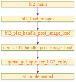
The following is the definition of its actual acquisition process :
static inline uint64_t el_implemented(unsigned int el)
{

	if (el > 3U) {

		return EL_IMPL_NONE;
	} else {

		unsigned int shift = ID_AA64PFR0_EL1_SHIFT * el;

		return (read_id_aa64pfr0_el1() >> shift) & ID_AA64PFR0_ELX_MASK;    (1)
	}
}

static uint32_t qemu_get_spsr_for_bl33_entry(void)
{

	…
	mode = (el_implemented(2) != EL_IMPL_NONE) ? MODE_EL2 : MODE_EL1;    (2)
	spsr = SPSR_64(mode, MODE_SP_ELX, DISABLE_ALL_EXCEPTIONS);       (3)
	…
}
(1) This function passes through reading id_aa64pfr0_el1 The register determines whether the given exception level is supported , The definition of this register is as follows :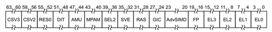
That is, judge whether the field corresponding to the given exception level in the register is set , If it is set cpu Support this exception level , Otherwise, it doesn't support
(2) if cpu Support EL2, be uboot from EL2 start-up , Otherwise, from EL1 start-up
(3) Set the startup mode to non secure Contextual spsr Among members , The context is exiting bl31 It will be set to the actual register
2.1.2 Determination of kernel startup exception level
uboot Act as firmware Support runs on EL1 – EL3 Any level of , But the kernel can only run on EL 1 or EL2. So before entering the kernel ,uboot You need to switch to the corresponding abnormal level according to the actual situation .
After loading the kernel , It will pass. boot_jump_linux Perform the actual switching process , among aarch64 The architecture process is as follows :
static void boot_jump_linux(bootm_headers_t *images, int flag)
{

	…
#ifdef CONFIG_ARMV8_SWITCH_TO_EL1
		printf("switch to EL1 AARCH64\n");
		armv8_switch_to_el2((u64)images->ft_addr, 0, 0, 0,
				    (u64)switch_to_el1, ES_TO_AARCH64);          (1)
#else
		if ((IH_ARCH_DEFAULT == IH_ARCH_ARM64) &&
		    (images->os.arch == IH_ARCH_ARM)) {

		    printf("switch to EL2 AARCH32\n");
			armv8_switch_to_el2(0, (u64)gd->bd->bi_arch_number,
					    (u64)images->ft_addr, 0,
					    (u64)images->ep,
					    ES_TO_AARCH32);                       (2)
		} else {

			printf("switch to EL2 AARCH64\n");
			armv8_switch_to_el2((u64)images->ft_addr, 0, 0, 0,
					    images->ep,
					    ES_TO_AARCH64);                        (3)
		}
#endif
…
}
armv8_to_el2 Will get cpu Current exception level of , And determine the running level of the kernel according to this value . If configured CONFIG_ARMV8_SWITCH_TO_EL1 Compulsory from EL1 start-up , No matter where it is currently running EL Next , All switch to EL1 Start the kernel again . If currently in EL3 perform , You need to switch to EL2 Start the kernel again . otherwise , The kernel will follow uboot Of EL. The relationship can be expressed in the following table :
| Current exception level | CONFIG_ARMV8_SWITCH_TO_EL1 Value | Kernel exception level |
|---|---|---|
| EL1 | yes | EL1 |
| EL1 | no | El1 |
| EL2 | yes | EL1 |
| EL2 | no | El2 |
| EL3 | yes | EL1 |
| EL3 | no | EL2 |
The following is its code implementation , Students who are not interested can skip directly :
(1) By configuring the parameters CONFIG_ARMV8_SWITCH_TO_EL1 Force the kernel to EL1 Run under . In this process armv8_switch_to_el2 Jump to the first switch_to_el1 function , Then from switch_to_el1 Perform actual exception level switching and kernel startup
(2) if os Need to run on aarch32 state , Then pass in the corresponding parameter
(3) if os Need to run on aarch64 state , Then pass in the corresponding parameter . Because the current mainstream architecture is aarch64, Therefore, we only pay attention to the following architecture related code aarch64 Related branches
armv8_switch_to_el2 The process is as follows :
ENTRY(armv8_switch_to_el2)
	switch_el x6, 1f, 0f, 0f               (a)
0:
	cmp x5, #ES_TO_AARCH64
	b.eq 2f
	bl armv8_el2_to_aarch32
2:
	br x4                                  (b)
1:	armv8_switch_to_el2_m x4, x5, x6       (c)
ENDPROC(armv8_switch_to_el2)
It depends on the currently running exception level , Identify the branches that need to be taken . because uboot Can be executed in EL1、EL2 or EL3 Next , Therefore, different processes are performed here . Through the following switch_el The definition of , It can be seen that the current abnormal level of operation is different , The jump branches are as follows :
| Current exception level | Jump tags |
|---|---|
| EL1 | 0 |
| EL2 | 0 |
| EL3 | 1 |
.macro	switch_el, xreg, el3_label, el2_label, el1_label
	mrs	\xreg, CurrentEL
	cmp	\xreg, 0xc
	b.eq	\el3_label
	cmp	\xreg, 0x8
	b.eq	\el2_label
	cmp	\xreg, 0x4
	b.eq	\el1_label
.endm
(a) The current exception level is EL3 when , adopt armv8_switch_to_el2_m Switch to EL2 And start the kernel . The current exception level is EL1 or EL2, According to the running state of the kernel aarch32 still aarch64, Switch first cpu state , Then jump to the entry function given by the parameter
(b) If not defined CONFIG_ARMV8_SWITCH_TO_EL1, Then this function will jump directly to the kernel entry function to start the kernel , At this time, the exception level of the kernel is the same as uboot The abnormal level of the current operation is the same . If you define CONFIG_ARMV8_SWITCH_TO_EL1, It will jump to switch_to_el1 Interface ,cpu Switch to EL1, Then start the kernel
(c) Change the exception level from EL3 Switch to EL2, Then start the kernel
2.2 The exception level of the kernel runtime
uboot Maybe EL1 or EL2 Start the kernel in this way , In the discussion in the last chapter, we know that the kernel should work in EL2 need vhe Support for . So if the kernel uses EL2 start-up , It must be further processed to determine whether it is running on El2 Of vhe Pattern , Or downgrade to EL1. The following is its code implementation :
SYM_FUNC_START(init_kernel_el)
	mrs	x0, CurrentEL
	cmp	x0, #CurrentEL_EL2
	b.eq	init_el2                                           (1)

SYM_INNER_LABEL(init_el1, SYM_L_LOCAL)
	mov_q	x0, INIT_SCTLR_EL1_MMU_OFF
	msr	sctlr_el1, x0                                        (2)
	isb
	mov_q	x0, INIT_PSTATE_EL1
	msr	spsr_el1, x0
	msr	elr_el1, lr                                          (3)
	mov	w0, #BOOT_CPU_MODE_EL1                               (4)
	eret                                                     (5)

SYM_INNER_LABEL(init_el2, SYM_L_LOCAL)
	mov_q	x0, HCR_HOST_NVHE_FLAGS
	msr	hcr_el2, x0                                          (6)
	isb

	init_el2_state                                           (7)

	adr_l	x0, __hyp_stub_vectors
	msr	vbar_el2, x0                                         (8)
	isb

	mrs	x0, hcr_el2
	and	x0, x0, #HCR_E2H
	cbz	x0, 1f                                               (9)

	mov_q	x0, INIT_SCTLR_EL1_MMU_OFF
	msr_s	SYS_SCTLR_EL12, x0                               (10)

	mov	x0, #INIT_PSTATE_EL2
	msr	spsr_el1, x0
	adr	x0, __cpu_stick_to_vhe
	msr	elr_el1, x0                                          (11)
	eret

1:
	mov_q	x0, INIT_SCTLR_EL1_MMU_OFF
	msr	sctlr_el1, x0

	msr	elr_el2, lr
	mov	w0, #BOOT_CPU_MODE_EL2
	eret

__cpu_stick_to_vhe:
	mov	x0, #HVC_VHE_RESTART
	hvc	#0
	mov	x0, #BOOT_CPU_MODE_EL2
	ret
SYM_FUNC_END(init_kernel_el)
(1) Get the exception level of the current operation , If it is EL1 Direct access init_el1 Handle , Otherwise enter init_el2
(2 - 5) For initialization EL1 Implementation status of , Such as sctlr_el1、spsr_el1, And pass eret take spsr_el1 Set to PSATE in , And execute function return
(6) initialization hcr_el2 Register value , This register is used for configuration hypervisor Properties of . Such as E2H Field is used to switch pairs vhe Support for ,TGE Field determines that it needs to be routed to EL1 Whether the exception of is routed to EL2 etc.
(7) This macro is used to initialize el2 The state of , Its definition is as follows :
.macro init_el2_state
		__init_el2_sctlr
		__init_el2_timers
		__init_el2_debug
		__init_el2_lor
		__init_el2_stage2
		__init_el2_gicv3
		__init_el2_hstr
		__init_el2_nvhe_idregs
		__init_el2_nvhe_cptr
		__init_el2_nvhe_sve
		__init_el2_fgt
		__init_el2_nvhe_prepare_eret
.endm
Here we focus on __init_el2_nvhe_prepare_eret, This macro will spsr The next exception level in is set to EL1, The perform eret after cpu Will switch to EL1 state . The following is the definition of this macro :
.macro __init_el2_nvhe_prepare_eret
	mov	x0, #INIT_PSTATE_EL1
	msr	spsr_el2, x0
.endm

#define INIT_PSTATE_EL1 \ (PSR_D_BIT | PSR_A_BIT | PSR_I_BIT | PSR_F_BIT | PSR_MODE_EL1h)
(8) by el2 Set up a stub Processing function , After setting up el2 Will be able to use this function to handle hvc Exception called
(9)HCR_EL2.E2H Bit is used to indicate whether vhe characteristic , If not, jump to the label 1 It's about , take cpu Jump back EL1.
(10) Enabled vhe after , Direct access el1 The system register of will be redirected to the corresponding el2 register , and hypervisor Sometimes you need to access the actual el1 register . therefore armv8 The architecture extends it , Can make vhe If you need to visit el1 register , You can visit xxx_el12 Realization
(11) here host Running on the el2 in , Yes el1 The operation of the register will be converted to the corresponding el2 register . Therefore, although currently running on EL2, But setting spsr_el1 and elr_el1 It's equivalent to setting spsr_el2 and elr_el2. From below INIT_PSTATE_EL2 The definition of , adopt eret After the exception returns ,cpu Still working on el2 handler Pattern .
#define INIT_PSTATE_EL2 \ (PSR_D_BIT | PSR_A_BIT | PSR_I_BIT | PSR_F_BIT | PSR_MODE_EL2h)
But before returning to the main function , It needs to go through __cpu_stick_to_vhe Of hvc The order fell into hypervisor Of stub handler Chinese vs vhe To initialize
The following table is a summary of the above :
| Kernel boot EL | Whether to enable VHE | The kernel runs EL |
|---|---|---|
| EL1 | NA | EL1 |
| EL2 | no | EL1 |
| EL2 | yes | EL2 |
3 The kernel starts memory management
3.1 Address independent code
Due to the kernel link address and uboot The actual jump entry address is different , When it first started pc The address is uboot Jump to the entry address . here cpu The first instruction can be obtained from this address , thereafter pc You can take the fingers in turn by self increment .
Because the virtual address after code and data link is specified in the linking process of the kernel , That is, after the kernel link is completed , The virtual address of each symbol has been determined , That is, an instruction ( And of course PC The instruction that the pointer points to ) The relative offset with other symbols has also been determined .
Therefore, the jump instruction can pass pc+ offset Calculate jump address by relative addressing method of . Memory access operations can also calculate addresses in a similar way to jump instructions . As shown in the following figure, you need to obtain symbols A The address of , You can go through PC + offset obtain :
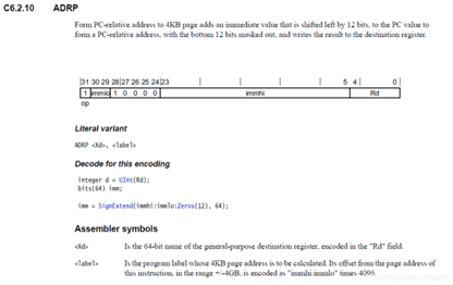
Of course, this memory operation mode needs the support of instruction set ,armv8 There are corresponding instructions in to realize this function , They are adr and adrp Instructions , Its description is shown in the figure below . because adr The immediate number in the instruction code accounts for 21 position (immlo 2 Place plus immhi 19 position ), Therefore, it is relative to PC The maximum address offset of is before and after 1M. and adrp The order is based on 4k Unit , Therefore, its addressing range reaches before and after 4G, But every address needs 4k alignment .
By its format ADR(ADRP) <Xd> <label> You know , We just need to give a symbol , It can automatically according to PC Value calculates the address of the symbol , Both in the Xd In the register . Because it is calculated by relative offset , Therefore, the instruction has another feature . If PC The physical address is stored in the , Then the calculated symbolic address is also a physical address , conversely , if PC The virtual address is stored in , Then the calculated symbolic address is also a virtual address , This feature will also be used in our later analysis .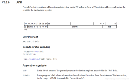
3.2 How the kernel finds memory
uboot The last step is to copy the kernel to memory , Then jump to its entry address and execute . So when the kernel starts, it is already in memory , But at this time, the kernel does not know the specific information of physical memory , Such as memory size,bank Information, etc , In fact, they are located in dtb Of memory In nodes , So we have to wait until the kernel is parsed dtb After the relevant information , To understand the complete information of physical memory .
Here is one of them dts Examples in , In this example, there is only one memory bank, Starting physical address 0x80000000, Memory size by 0x80000000.
[email protected]80000000 {

		device_type = "memory";
		reg = <0x00000000 0x80000000 0 0x80000000>;
	};
System analysis dtb The code flow of initializing the memory module is as follows :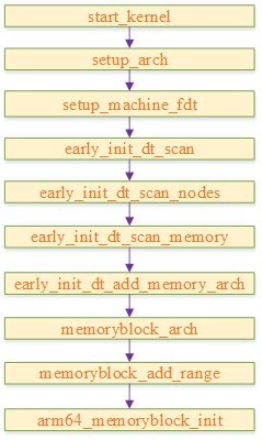
3.3 Arm64 Virtual address space for
We know that 32 The virtual address space in the bit system is divided into two parts , The general configuration is 0 - 3G The virtual address space will be allocated to users ,3G - 4G Will be allocated to the kernel virtual address space . Because the kernel only 1G Virtual address space , So the kernel divides it , lower than 896M The space of is used for direct mapping , And its access is higher than 896M High end memory , It needs to be in 3G + 896M To 4G Find a virtual address for it to build a page table . Because this virtual address is logically divided into several parts , Therefore, there are several different ways of high-end mapping , For example, it can be temporary mapping , After the access is completed, unmap to free the virtual address space , It can also be permanent mapping , The details are no longer expanded .
about arm64, Because it is 64 An architecture , Both user space and kernel space contain a large enough range of virtual addresses , Therefore, all kernel addresses can be directly mapped to the virtual address space of the kernel , There is no need to keep high-end memory . In practical applications ,arm64 Will not use all 64 Address of bit , Currently, the maximum number of users is 52 Bit virtual address , It can also be configured as 48 position ,42 position ,39 I'm waiting for you . For the convenience of discussion , Later, we will talk about arm64 Virtual address , Are subject to 48 Bit address and 4k Take page size as an example .
stay arm64 If you use 48 Virtual address of bit , Then the address allocation of kernel space and user space is as follows , among lower VA Will be used as user space ,upper VA Will be used as kernel space , The sizes are 256TB.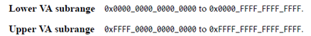
3.4 Mapping relationship between virtual address and physical address
arm64 Support 3 - 5 Class page table , The five level page table contains PGD,P4D,PUD,PMD,PTE, The fourth level page table does not contain P4D, The third level page table does not contain P4D and PUD, The rest is the same as the five level page table , For the sake of description , In the following analysis, we take the more common four level page table as an example .
Because the length of the page table descriptor is 8 byte , So when the page size by 4k when , If you want to pgd All of the entry Save to a page , Then it can contain 4096/8 term ( namely 2^9)pgd The descriptor , therefore pgd Containing virtual addresses at most 9 position , alike ,PUD,PMD and PTE It also contains virtual addresses at most 9 position . Therefore, in 48 Bit virtual address ,4k Page size ,4 The division of level page table is shown in the following figure :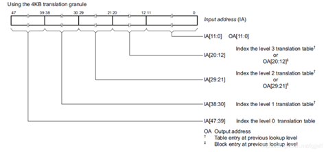
According to the above division ,PGD Each item in points to a PUD The base address ,PUD Each item in points to a PMD The base address ,PMD Every item of points to PTE The base address , and PTE Each item in points to the base address of a physical address page . Virtual address 39 - 47 Bit can determine that it is PGD The position in the table ,30 - 38 The position is decided in PUD Position in , By analogy .
therefore , Just know the virtual address and PGD The base address , You can find the physical address page through the page table , And the virtual address is low 12 Bit offset is the offset of the address in the physical page . Yes arm64 framework ,EL1 There are two registers in the TTBR0_EL1 and TTBR1_EL1 To preserve PGD The address of . As shown in the figure below , When we create the page table , And then PGD The base address of is stored in TTBRx_EL1 after ,CPU You already know how to translate virtual address and physical address . thereafter , We just need to set up SCTRL The register of M Bits can be enabled MMU, Run to the virtual address space .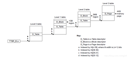
We said earlier arm64 stay EL1 There are two in mode PGD Base address register TTBR0_EL1 and TTBR1_EL1, What are their functions ? We know that virtual addresses are divided into kernel space and user space , Among them, the kernel space is 63 Position as 1, And the third part of user space 63 Position as 0, Therefore, by judging the number of virtual addresses 63 Bit can know whether the address belongs to kernel space or user space . therefore arm64 Put the user space page table PGD The base address of is stored in TTBR0_EL1 in , The kernel space page table PGD The base address of is stored in TTBR1_EL1 in . When MMU When converting virtual address to physical address , Will judge the first 63 position , If it is a user space address , Then use TTBR0_EL1 Page table pointed to , Otherwise use TTBR1_EL1 Page table of .
Of course , There are exceptions here , When creating the initial page table create_page_tables Function ,idmap Although the code of this section belongs to kernel space , But creating idmap Page table time , In fact, it is mapped to the low address virtual address space . The reason is that arm64 Modern processors, including, will adopt pipelined architecture , And has branch prediction , Disordered execution and other features , So in MMU On , except PC Open in MMU Out of order , Some instructions that need to be executed later have not yet entered PC, But it has completed operations such as finger retrieval or decoding . And when they take their fingers, it's still MMU off The state of , So its address is still a physical address .
To solve this problem , The kernel adopts a clever approach . the MMU Open the relevant code and put it in a separate file called idmap In the paragraph of , Then create a separate page table for this segment , The feature of this page table is that its virtual address is equal to the physical address , So in MMU In the process of enabling, the virtual address and physical address of the instruction that is fetched or decoded later are the same , So it solved MMU The address may not match when enabling switching . We know uboot Will copy the kernel to ram At the lower address of , So its physical address will be located in 0x0000 0000 0000 0000 To 0x0000 ffff ffff ffff Between , That is, its virtual address is also in this range , So this page table pgd The base address will be put ttbr0_el1 in .
Of course. create_page_tables Except for idmap Create pages outside the table , It also needs to be for the entire kernel image Create page table , To make the kernel in MMU After enabling, the code can be executed correctly . The virtual address of this part is defined as 0xffff 0000 0000 0000 To 0xffff ffff ffff ffff Between , So its page table pgd The base address will be placed in ttbr1_el1 in . obviously idmap Segment is also the kernel image Part of , Therefore, this part will be mapped twice , The physical address of this segment can be accessed through any corresponding virtual address in the two page tables ,MMU According to whether the highest bit of the virtual address is 1 To determine which page table to use for address translation .
3.5 create_page_tables Features of creating page tables
create_page_tables Function creates a total of two page tables idmap and init_pg_dir, Page table descriptor is saved bss Position after segment , Each level of page table occupies a page space . Suppose we use the four level page table described above , Refer to the table structure on this page ( We'll post it here for easy viewing ), because level 1 The page table only occupies one page , so level 0 There is actually only one page table entry It works , Empathy ,level 1 and level 2 There is only one page table entry It works . Therefore, the range of mapping space it can actually establish is 2^n * page_size, among n by 3 The number of digits in the level page table ,page_size For page size , When the page size is 4k, Three level page table 9 When a , The memory it can map is 2M.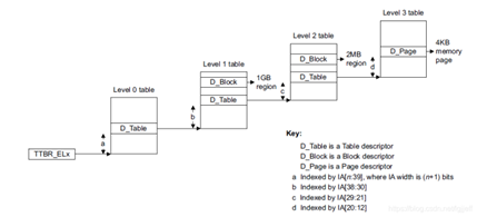
Obviously, this space is too small , So in arm64 in , When the page size is 4k Set up when idmap and init_pg_dir Page table will be enabled section maps Mechanism . The principle is to set the number of stages of the page table to be one less than the actual configuration value , Cancel the last page table . Take the above configuration as an example , be level 3 table Will be cancelled , Therefore, the address space range that the page table can map is 2M * 2^n, among n by 2 The number of digits in the level page table , stay 4k The value in the page table is 9, So in this case, the address range that can be mapped is 1G, This range is generally sufficient for the mapping of various parts in the initialization phase
边栏推荐
猜你喜欢

如何在博客中添加Aplayer音乐播放器
Distributed database master-slave configuration (MySQL)

Zhou Yajin, a top safety scholar of Zhejiang University, is a curiosity driven activist

科普达人丨一文弄懂什么是云计算?
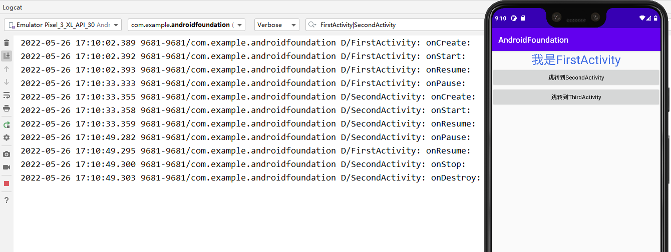
Activity生命周期
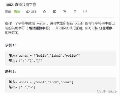
Force buckle 1002 Find common characters
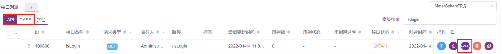
使用MeterSphere让你的测试工作持续高效
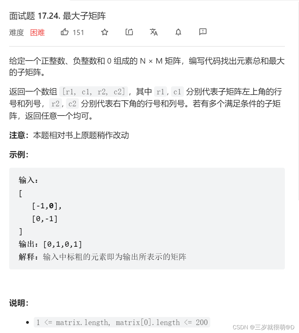
LeetCode - 面试题17.24 最大子矩阵
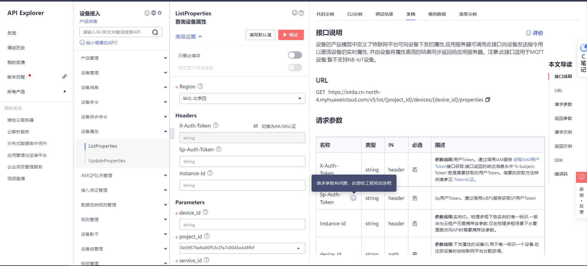
Design intelligent weighing system based on Huawei cloud IOT (STM32)
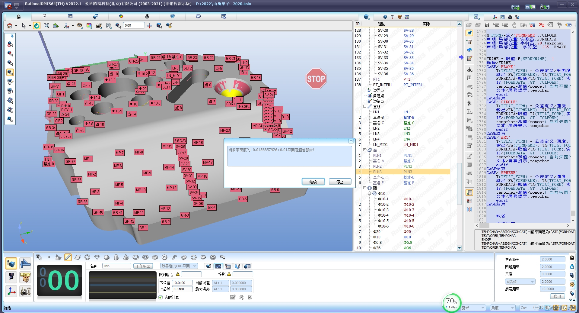
RationalDMIS2022 高级编程宏程序
随机推荐
Vscode 尝试在目标目录创建文件时发生一个错误:拒绝访问【已解决】
关于jmeter中编写shell脚本json的应用
STM32 entry development NEC infrared protocol decoding (ultra low cost wireless transmission scheme)
How to use cherry pick?
90后,辞职创业,说要卷死云数据库
自动化测试框架
JS array delete the specified element
Which securities company is the best and safest to open an account for the subscription of new shares
Use metersphere to keep your testing work efficient
‘module‘ object is not callable错误
audit 移植
聊聊SOC启动(十) 内核启动先导知识
electron添加SQLite数据库
【问道】编译原理
【C#】WinForm运行缩放(变糊)的解决方法
R语言使用magick包的image_mosaic函数和image_flatten函数把多张图片堆叠在一起形成堆叠组合图像(Stack layers on top of each other)
Socket socket programming
Antd select selector drop-down box follows the scroll bar to scroll through the solution
What if copying is prohibited?
Network protocol concept