当前位置:网站首页>Special topic of rotor position estimation of permanent magnet synchronous motor -- fundamental wave model and rotor position angle
Special topic of rotor position estimation of permanent magnet synchronous motor -- fundamental wave model and rotor position angle
2022-07-06 20:07:00 【Explain the motor in simple terms】
Preface
The topic of rotor position estimation of permanent magnet synchronous motor will be written as a series , The commonly used motor position estimation method of permanent magnet synchronous motor is decomposed into several subcategories , Then write the specific principles one by one . The style of the article is consistent with other articles , Keep it easy to understand , Without losing depth .
This is the opening work of this topic , First understand what angle the rotor position angle refers to , And connect it with the mathematical model .
List of articles
One 、 Rotor position angle of permanent magnet synchronous motor
This article wants to explain how to estimate the rotor position angle , This is a big topic , In order to make this problem clear , First of all, understand what is the rotor position angle .
First, I want to add the basic knowledge of permanent magnet synchronous motor , When doing permanent magnet synchronous motor control , We are concerned with the interaction between the stator and the rotor , This force is generated by the interaction of stator magnetic field and rotor magnetic field . The rotor of permanent magnet synchronous motor is a permanent magnet , After being produced , Its magnetic field is fixed , Its direction is rotor N The direction of the pole . The stator magnetic field is generated by current , The greater the current , The stronger the magnetic field generated , The magnitude of the magnetic field generated by each phase current is proportional to the current at the current moment , The direction is the direction of the phase in space . The total stator magnetic field is the vector sum of the magnetic field generated by the three-phase current .
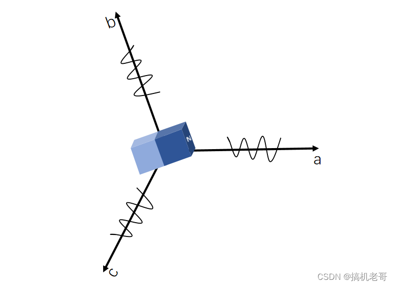
Take a pair of pole permanent magnet synchronous motor as an example , The simplified model is shown in the figure above .
In order to illustrate the spatial relationship of rotor position angle , Here, it is analyzed to use the pre positioning method to drag the rotor to 0° The process of .
Make i d = 10 A , i q = 0 , f o c A n g l e = 0 ; id = 10A,iq = 0,focAngle = 0; id=10A,iq=0,focAngle=0;
Carry out counter-measures park Transformation and inversion clark Transformation
[ i α i β ] = [ c o s θ s i n θ − s i n θ c o s θ ] [ i d i q ] (1) \left[\begin{array}{c} i_{\alpha }\\ i_{\beta } \end{array}\right] = \left[\begin{array}{c} cos\theta&sin\theta\\ -sin\theta & cos\theta \end{array}\right] \left[\begin{array}{c} i_{d }\\ i_{q } \end{array}\right] \tag{1} [iαiβ]=[cosθ−sinθsinθcosθ][idiq](1)
back park Transformation
[ i a i b i c ] = 2 3 [ 1 0 − 1 2 3 2 − 1 2 − 3 2 ] [ i α i β ] (2) \left[\begin{array}{c} i_{a}\\ i_{b} \\ i{c} \end{array}\right] = \frac{2}{3} \left[\begin{array}{c} 1 & 0\\ -\frac{1}{2} & \frac{\sqrt3}{2} \\ -\frac{1}{2} & -\frac{\sqrt3}{2} \end{array}\right] \left[\begin{array}{c} i_{\alpha }\\ i_{\beta } \end{array}\right] \tag{2} ⎣⎡iaibic⎦⎤=32⎣⎢⎡1−21−21023−23⎦⎥⎤[iαiβ](2)
back clark Transformation
Into the Make i d = 10 A , i q = 0 , f o c A n g l e = 0 id = 10A,iq = 0,focAngle = 0 id=10A,iq=0,focAngle=0, Yes i α = 10 A , i β = 0 ; i a = 6.67 A , i b = − 3.3 A , i c = − 3.3 A i_{\alpha} = 10A, i_{\beta} = 0; i_a = 6.67A,i_b = - 3.3A,i_c = -3.3A iα=10A,iβ=0;ia=6.67A,ib=−3.3A,ic=−3.3A
Put it in the picture above , Vector synthesis , No matter in α β \alpha \beta αβ Coordinate system , Still a b c abc abc Coordinate system , The same conclusion can be reached , The direction and of the composite vector a Axis coincidence , The size is 10A;
So when the position angle of the pre positioned rotor is 0 When the degree of , Get one Direction and a Stator magnetic field with coincident shafts , Pull the rotor to a Axis direction . It can also be said that the rotor position angle is 0 When the degree of , rotor N Pole position and a Phase stator coils coincide , Here we are , The following statement has been verified : The rotor position angle refers to the rotor in space N Pole and stator a Electrical included angle of phase winding .
Rotor position angle here , Also called vector angle , Pole position angle , Different industries have different customary names .
Two 、 Where does the rotor position angle react
To estimate the rotor position , You must know when the rotor position is in different positions , How will you react . stay abc Coordinate system , Three phase voltage 、 electric current 、 flux linkage , Coupled with each other , The mathematical model is complex , Common rotor position estimation methods are α β \alpha \beta αβ Coordinate system .
2.1 α β \alpha \beta αβ Mathematical model in coordinate system
Let's first look at the voltage equation
[ v α v β ] = [ i α i β ] R s + d d t [ ϕ α ϕ β ] (3) \left[\begin{array}{c} v_{\alpha }\\ v_{\beta } \end{array}\right] = \left[\begin{array}{c} i_{\alpha }\\ i_{\beta } \end{array}\right] R_s + \frac{d}{dt} \left[\begin{array}{c} \phi_{\alpha }\\ \phi_{\beta } \end{array}\right] \tag{3} [vαvβ]=[iαiβ]Rs+dtd[ϕαϕβ](3)
among ϕ α ϕ β \phi_{\alpha} \phi_{\beta} ϕαϕβ Express α β \alpha \beta αβ Axial flux linkage
[ ϕ α ϕ β ] = [ c o s θ s i n θ − s i n θ c o s θ ] [ L s i d + ϕ f L s i q ] (4) \left[\begin{array}{c} \phi_{\alpha }\\ \phi_{\beta } \end{array}\right] = \left[\begin{array}{c} cos\theta&sin\theta\\ -sin\theta & cos\theta \end{array}\right] \left[\begin{array}{c} L_s i_{d } + \phi_f\\ L_s i_{q } \end{array}\right] \tag{4} [ϕαϕβ]=[cosθ−sinθsinθcosθ][Lsid+ϕfLsiq](4)
hold d q dq dq The axis flux linkage changes to α β \alpha \beta αβ Axis
[ ϕ α ϕ β ] = [ i α i β ] L s + [ ϕ f c o s θ ϕ f s i n θ ] (5) \left[\begin{array}{c} \phi_{\alpha }\\ \phi_{\beta } \end{array}\right] = \left[\begin{array}{c} i_{\alpha }\\ i_{\beta } \end{array}\right]L_s+ \left[\begin{array}{c} \phi_{f }cos\theta\\ \phi_{f}sin\theta \end{array}\right] \tag{5} [ϕαϕβ]=[iαiβ]Ls+[ϕfcosθϕfsinθ](5)
among ϕ f \phi_f ϕf Indicates permanent magnet flux linkage .
Relative to the above form of voltage equation , I think more friends are more familiar with the following forms
[ v α v β ] = [ i α i β ] R s + d d t [ L s i α L s i β ] + [ − ω e ϕ f s i n θ ω e ϕ f c o s θ ] (6) \left[\begin{array}{c} v_{\alpha }\\ v_{\beta } \end{array}\right] = \left[\begin{array}{c} i_{\alpha }\\ i_{\beta } \end{array}\right] R_s + \frac{d}{dt} \left[\begin{array}{c}L_s i_{\alpha }\\L_s i_{\beta } \end{array}\right] + \left[\begin{array}{c}- \omega_e \phi_{f } sin\theta \\ \omega_e\phi_{f}cos\theta \end{array}\right] \tag{6} [vαvβ]=[iαiβ]Rs+dtd[LsiαLsiβ]+[−ωeϕfsinθωeϕfcosθ](6)
among ω e \omega_e ωe Is the electrical angular velocity .
But compared to (6),(4) and (5) Easier to explain
2.2 α β \alpha \beta αβ The rotor flux linkage component of the shaft contains position information
(4) in , α β \alpha \beta αβ The flux linkage of the shaft is composed of d q dq dq Axial flux linkage ipark transformation , among , d d d The axis flux linkage is composed of L s i d L_s i_{d } Lsid and ϕ f \phi_f ϕf Two parts , I said before. , d d d The position of the shaft is defined as a permanent magnet N N N The direction of the pole , So permanent magnet flux linkage ϕ f \phi_f ϕf Is only found in d d d Axis , The other part is the current flowing d d d Stator flux linkage generated by shaft inductance L s i d L_s i_{d } Lsid ; q q q The shaft has only stator flux L s i q L_s i_{q } Lsiq.
take (4) Medium ipark Transform expansion , Get the formula (5)
You can see ,** The flux linkage in the air gap of permanent magnet synchronous motor is composed of two parts , One part is stator flux [ i α i β ] L s \left[\begin{array}{c} i_{\alpha }\\ i_{\beta } \end{array}\right]L_s [iαiβ]Ls, It is generated by the current flowing through the stator coil , The other part is rotor flux [ ϕ f c o s θ ϕ f s i n θ ] \left[\begin{array}{c} \phi_{f }cos\theta\\ \phi_{f}sin\theta \end{array}\right] [ϕfcosθϕfsinθ], Produced by the rotor permanent magnet .
α β \alpha \beta αβ The rotor flux linkage component in the coordinate system contains the rotor angle information .
2.3 α β \alpha \beta αβ The back EMF voltage component of the shaft contains position information
take (5) Plug in (3) obtain (6), This formula is common α β \alpha \beta αβ Expression of voltage equation in coordinate system . We know that changes in the magnetic field produce an electric field , In permanent magnet synchronous motor , The stator coil of each phase is wound around the stator core to form a closed space , In this space , Flux linkage changes , Voltage is formed at both ends of the coil , The faster the flux linkage changes , The greater the voltage generated . [ − ω e ϕ f s i n θ ω e ϕ f c o s θ ] \left[\begin{array}{c}- \omega_e \phi_{f } sin\theta \\ \omega_e\phi_{f}cos\theta \end{array}\right] [−ωeϕfsinθωeϕfcosθ] Describes the voltage generated by the rotation of the rotor magnetic field , Relationship with rotor speed and current rotor angle , This part of voltage is also called back EMF ; [ L s i α L s i β ] \left[\begin{array}{c}L_s i_{\alpha }\\L_s i_{\beta } \end{array}\right] [LsiαLsiβ] The relationship between voltage and current caused by the change of stator magnetic field is described .
α β \alpha \beta αβ The back EMF voltage component in the coordinate system contains the rotor angle information .
3、 ... and 、 Summary
This paper is the first article on the topic of rotor position estimation of permanent magnet synchronous motor , To ensure that the length of each article is not too long , End here . The common methods of rotor position estimation are decomposed into , α β \alpha \beta αβ Location estimation of fundamental wave model in coordinate system 、 d q dq dq Location estimation of fundamental wave model in coordinate system 、 Position estimation of injection signal class , Wait for multiple directions , Specific decomposition .
Like my article , Remember to pay attention .
边栏推荐
- 腾讯架构师首发,2022Android面试笔试总结
- Technology sharing | packet capturing analysis TCP protocol
- Method keywords deprecated, externalprocname, final, forcegenerate
- Monthly report of speech synthesis (TTS) and speech recognition (ASR) papers in June 2022
- AsyncHandler
- Standardized QCI characteristics
- AsyncHandler
- 颜色(color)转换为三刺激值(r/g/b)(干股)
- It's enough to read this article to analyze the principle in depth
- Example of shutter text component
猜你喜欢
枚举根据参数获取值
Tencent T3 Daniel will teach you hand-in-hand, the internal information of the factory
Node.js: express + MySQL实现注册登录,身份认证

Li Kou 101: symmetric binary tree
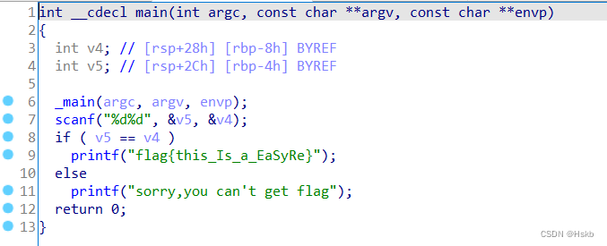
BUUCTF---Reverse---easyre
![[network planning] Chapter 3 data link layer (4) LAN, Ethernet, WLAN, VLAN](/img/b8/3d48e185bb6eafcdd49889f0a90657.png)
[network planning] Chapter 3 data link layer (4) LAN, Ethernet, WLAN, VLAN
腾讯T3手把手教你,真的太香了
PowerPivot - DAX (first time)
The "white paper on the panorama of the digital economy" has been released with great emphasis on the digitalization of insurance
腾讯安卓开发面试,android开发的基础知识
随机推荐
logstash高速入口
POJ 3207 Ikki's Story IV – Panda's Trick (2-SAT)
HDU 1026 search pruning problem within the labyrinth of Ignatius and the prince I
In simple terms, interview surprise Edition
Leetcode 30. Concatenate substrings of all words
AddressSanitizer 技术初体验
Introduction of Xia Zhigang
某东短信登录复活 安装部署教程
mod_wsgi + pymssql通路SQL Server座
Recursive implementation of department tree
Synchronization of data create trigger synchronization table for each site
5. 无线体内纳米网:十大“可行吗?”问题
Tencent byte Alibaba Xiaomi jd.com offer got a soft hand, and the teacher said it was great
Method keywords deprecated, externalprocname, final, forcegenerate
Cesium Click to draw a circle (dynamically draw a circle)
腾讯T3手把手教你,真的太香了
An East SMS login resurrection installation and deployment tutorial
After solving 2961 user feedback, I made such a change
Anaconda安装后Jupyter launch 没反应&网页打开运行没执行
腾讯T4架构师,android面试基础