当前位置:网站首页>Smart street lamp based on stm32+ Huawei cloud IOT design
Smart street lamp based on stm32+ Huawei cloud IOT design
2022-07-06 17:48:00 【InfoQ】
1. Preface
2. The specific functions and related hardware
3. Hardware selection
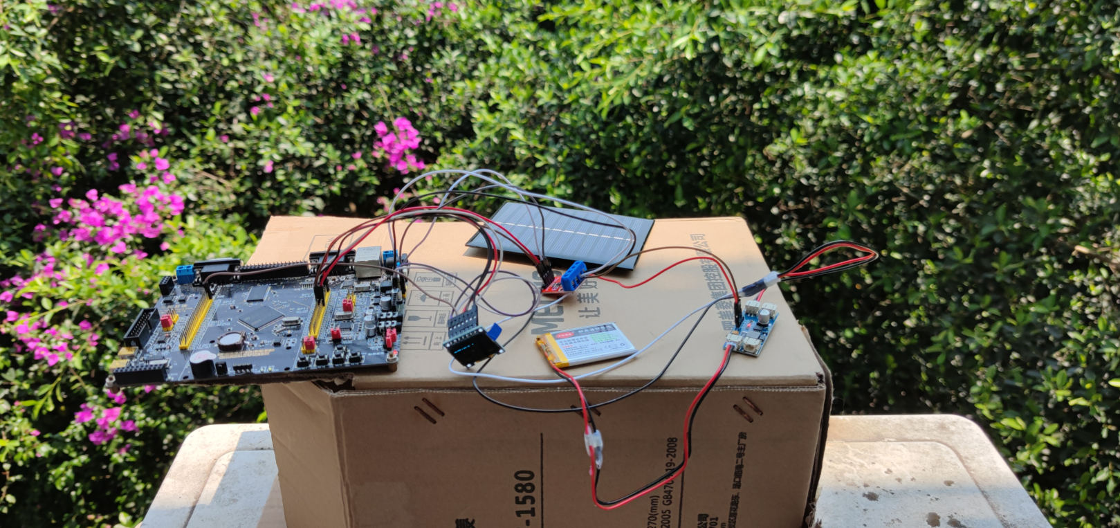
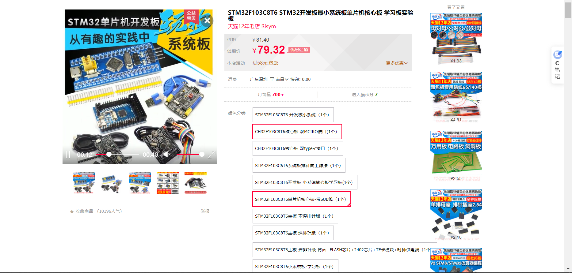
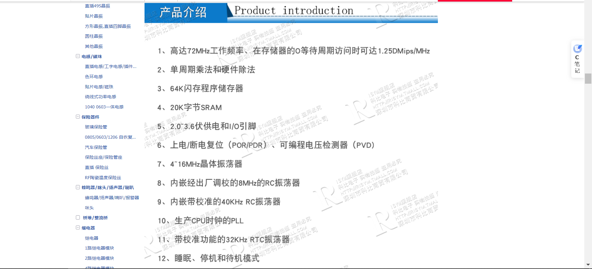
3.1 STM32F103C8T6
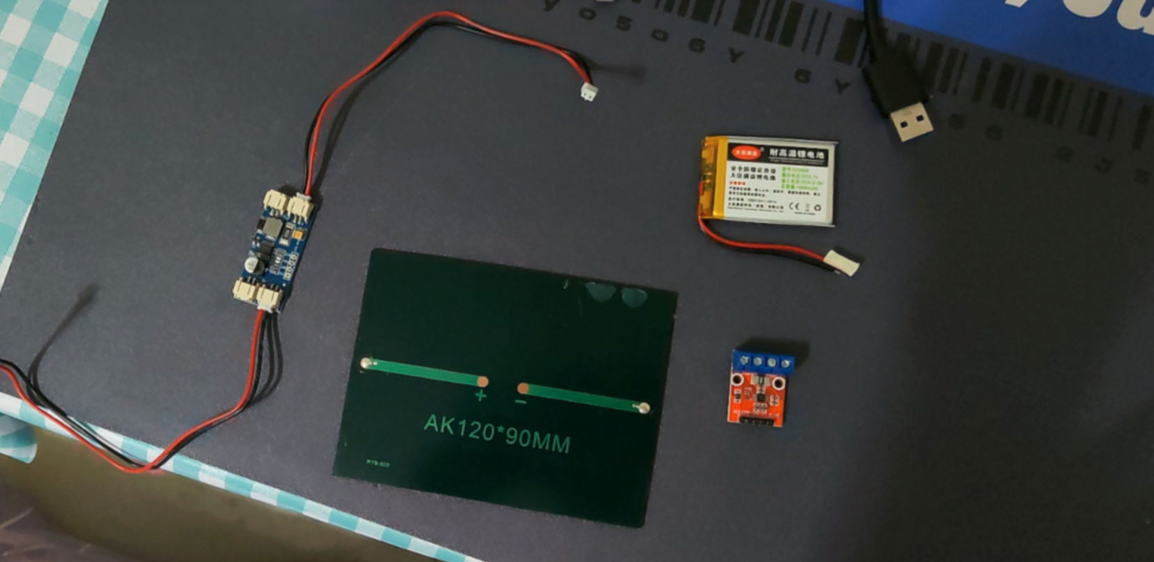
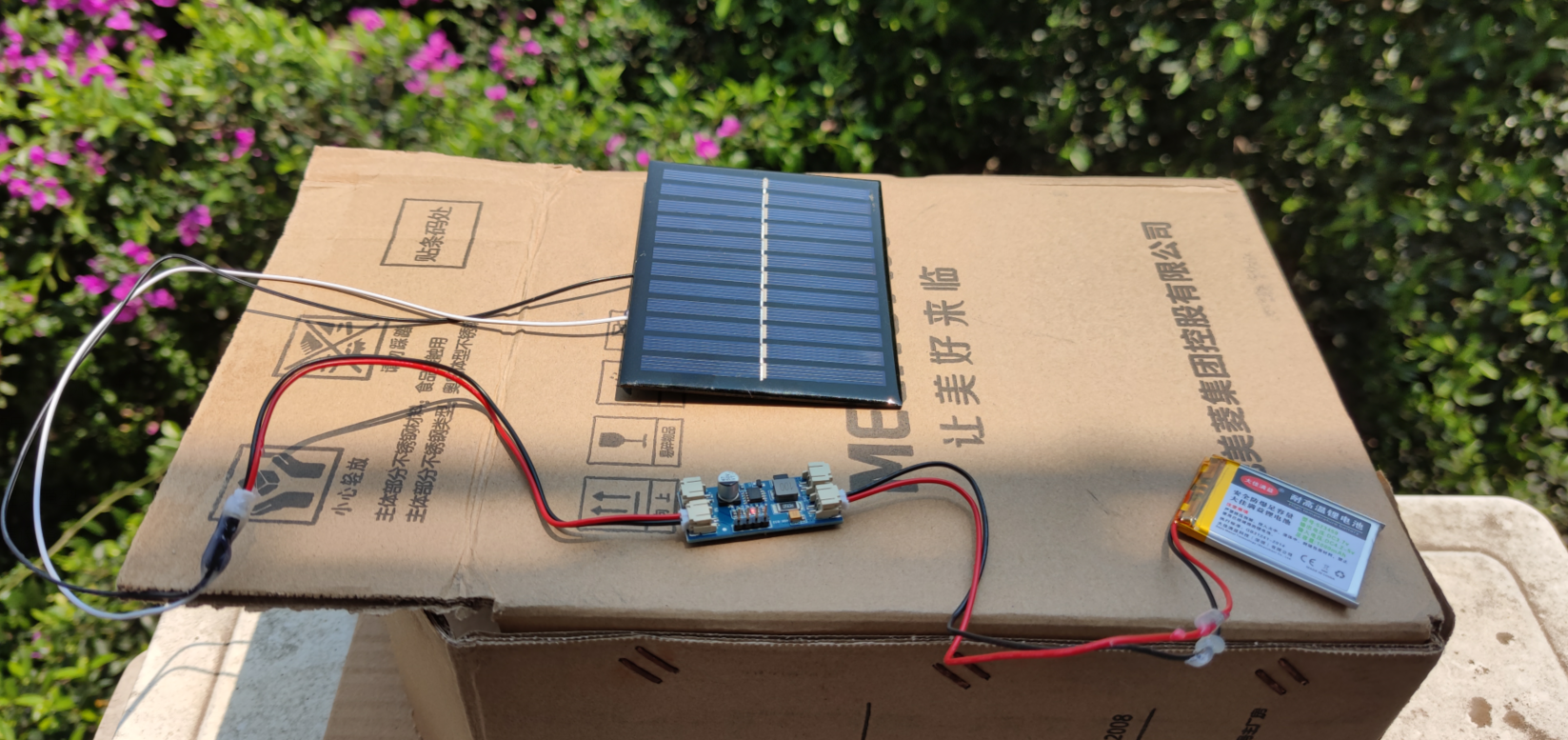
3.2 Solar panels

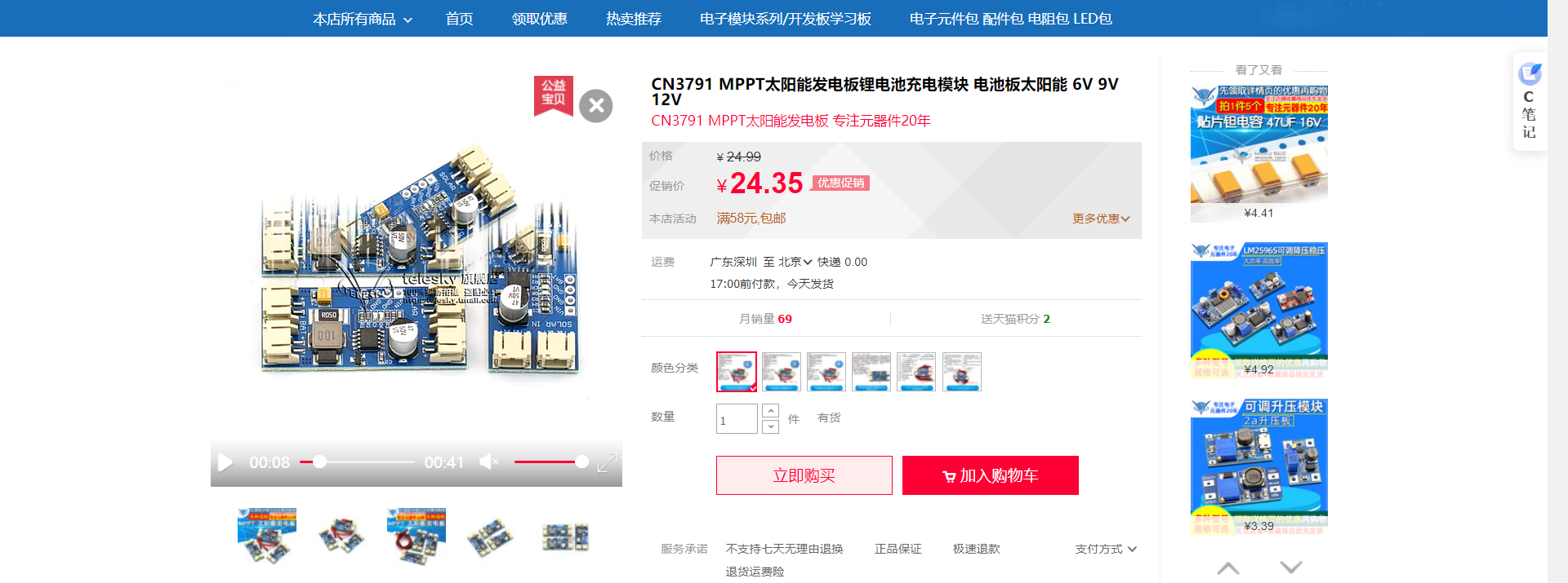
3.3 Lithium battery charging module
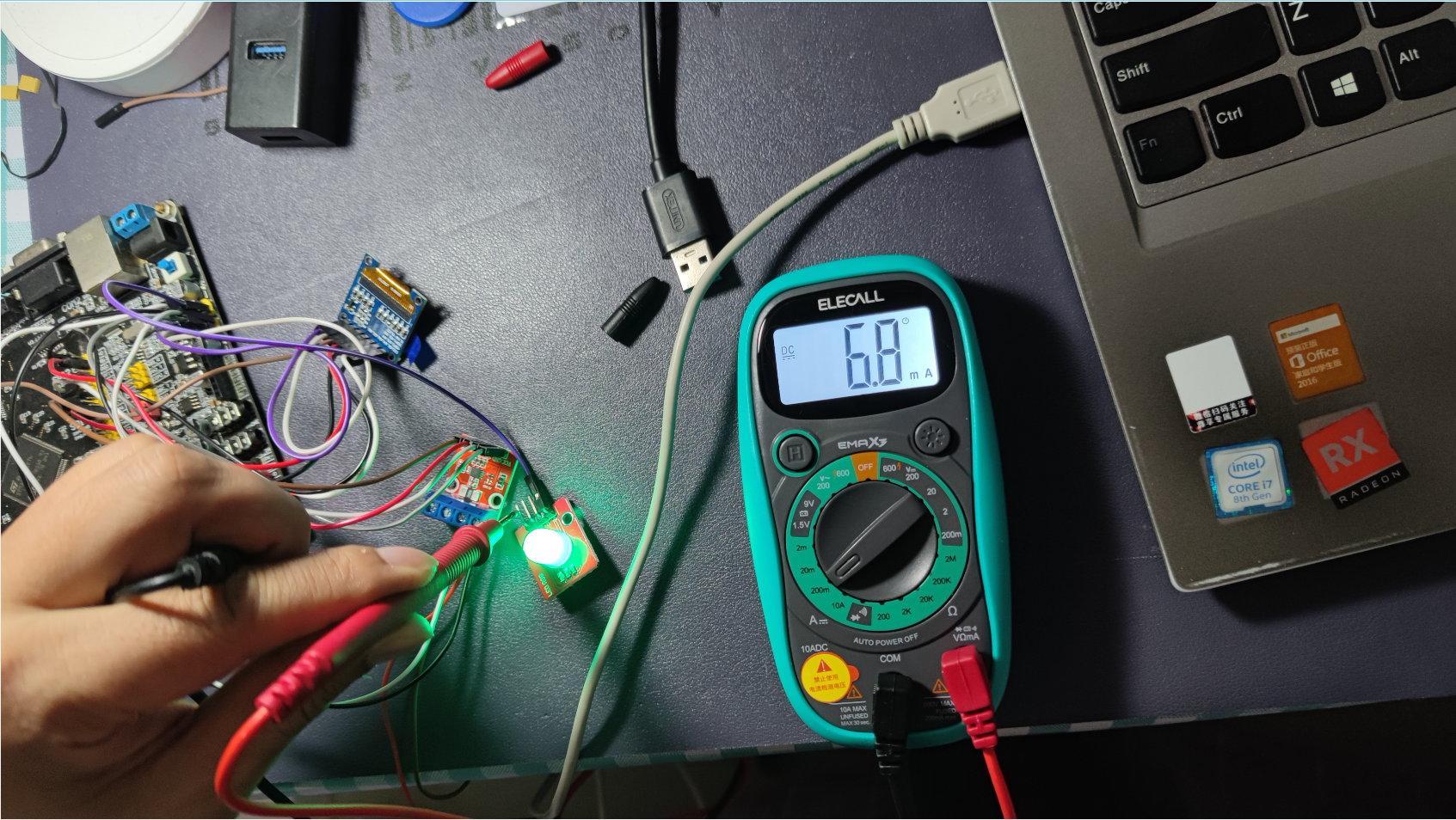
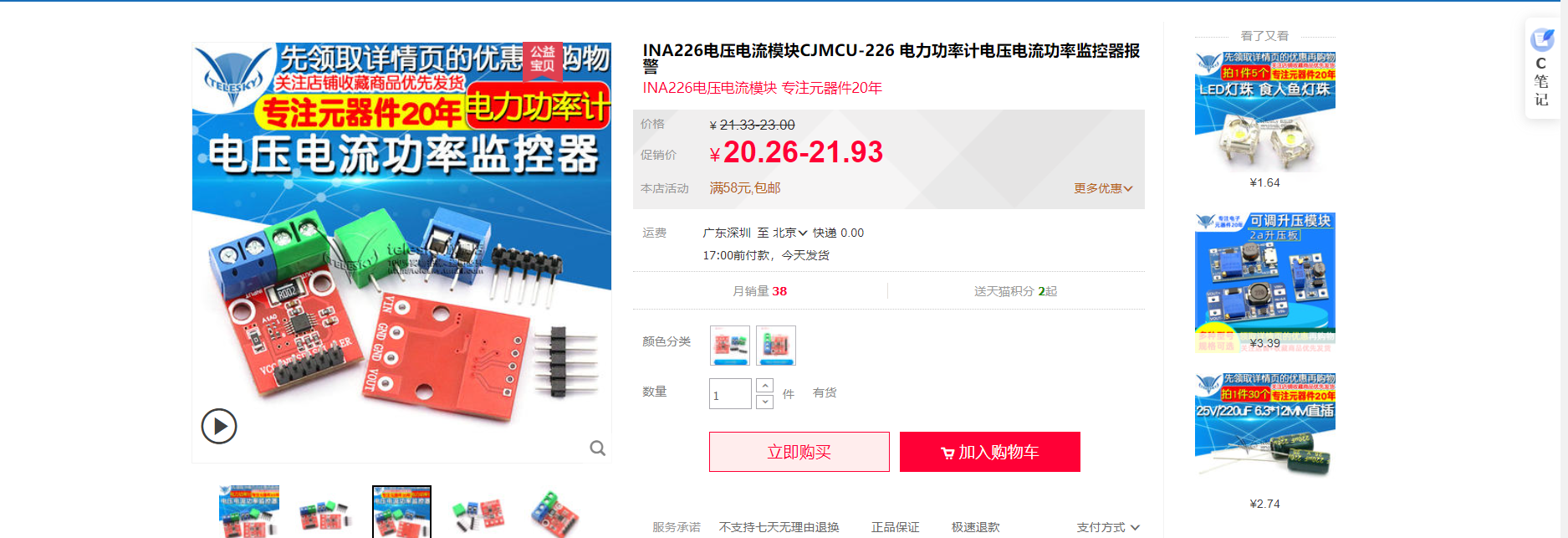
3.4 Power detection module
3.5 BH1750 Photosensitive sensors

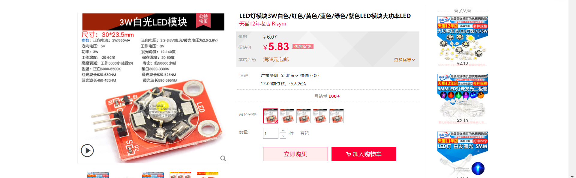
3.6 LED The lamp
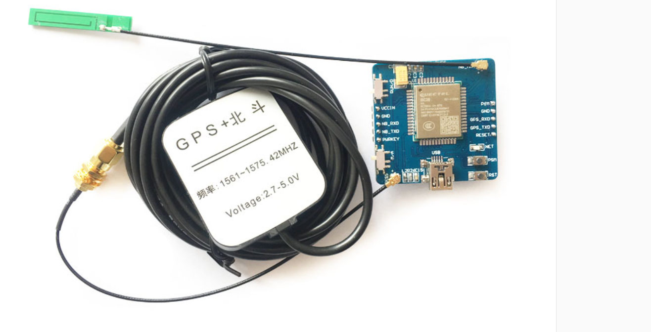
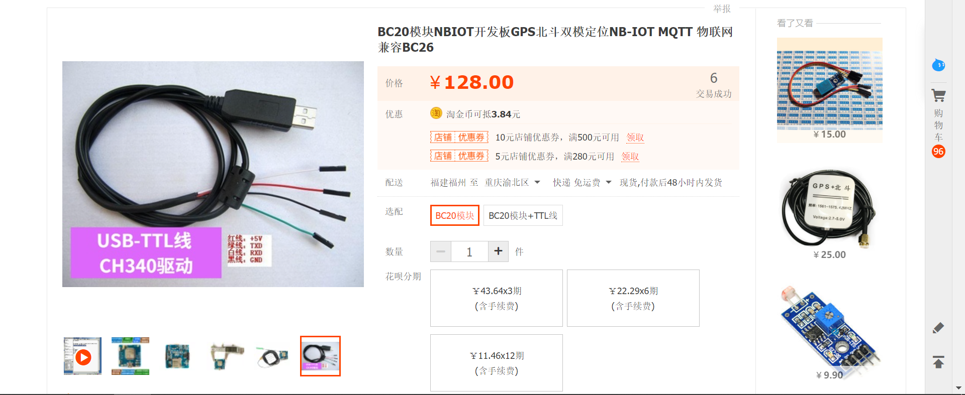
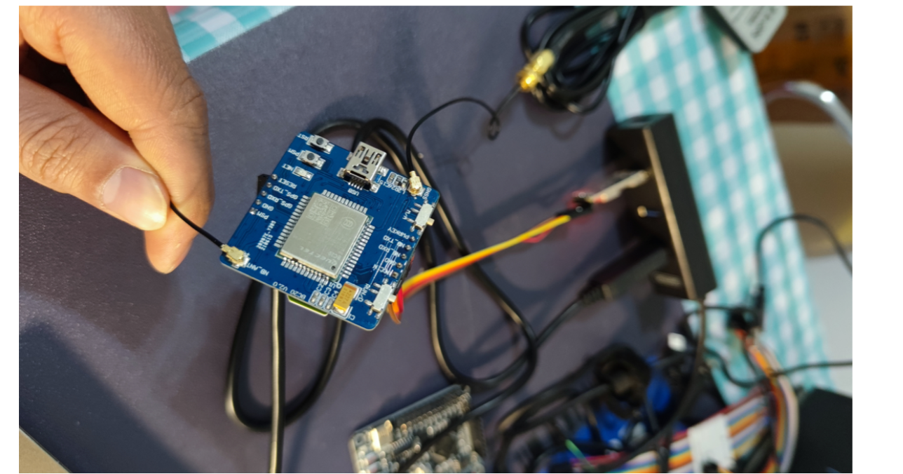
3.7 BC20-NBIOT modular
 model : BC20+BD+GPS
 brand :  Creative thinking
 Place of Origin :  The Chinese mainland
 Interface type : TTL
 Applicable scenario : NBIOT
 Size : 40x40x12mm
 Working current : 0.5A
 Support TCP/IP agreement :
 Support transmission rate : 115200Kbps
 Working voltage : 5V
 Whether voice call is supported :  no
 Module type :  other
 Whether SMS is supported :  no
 Support standard : GSM/GPRS(2G)
 Whether the phone book is supported :  no
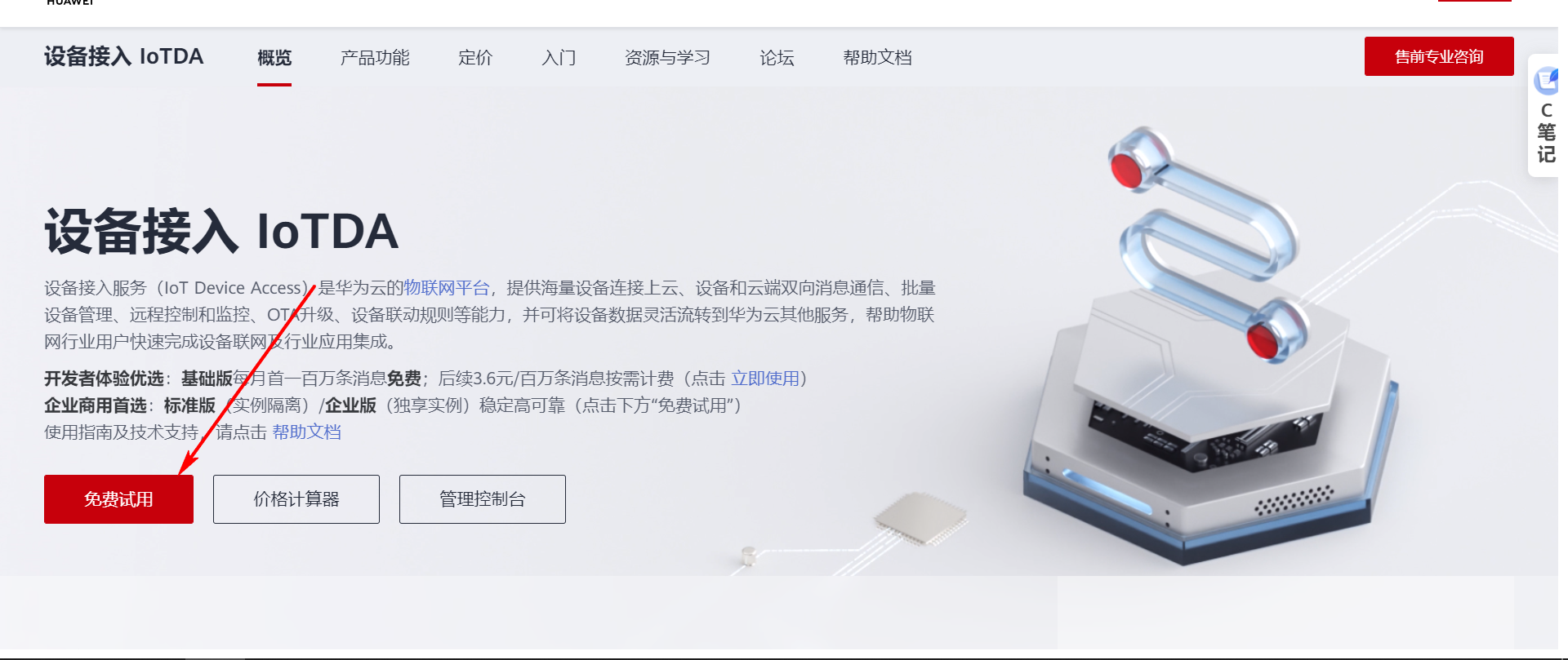
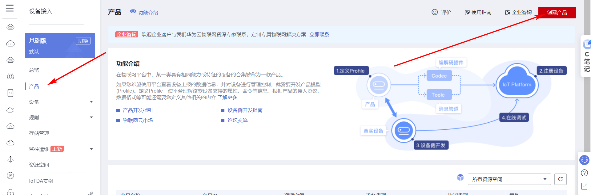
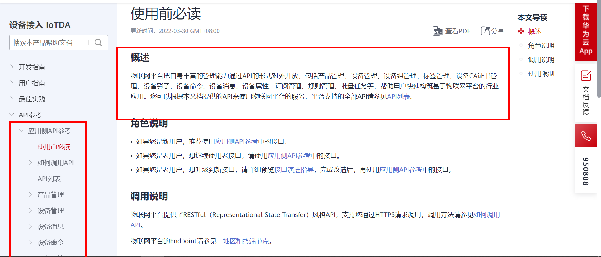
4. Create products and devices
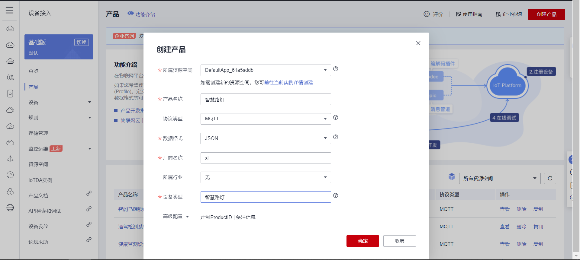
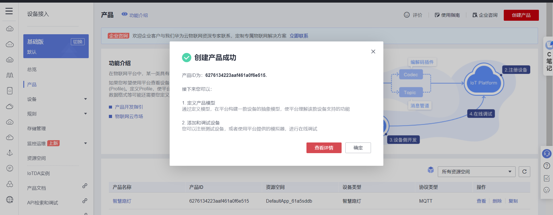
4.1 Create products
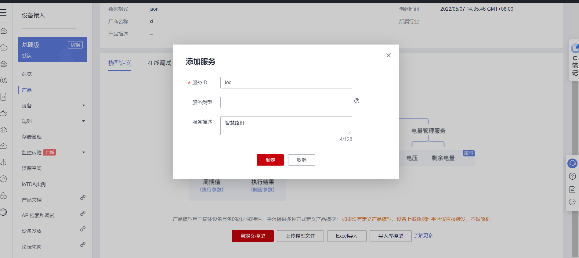
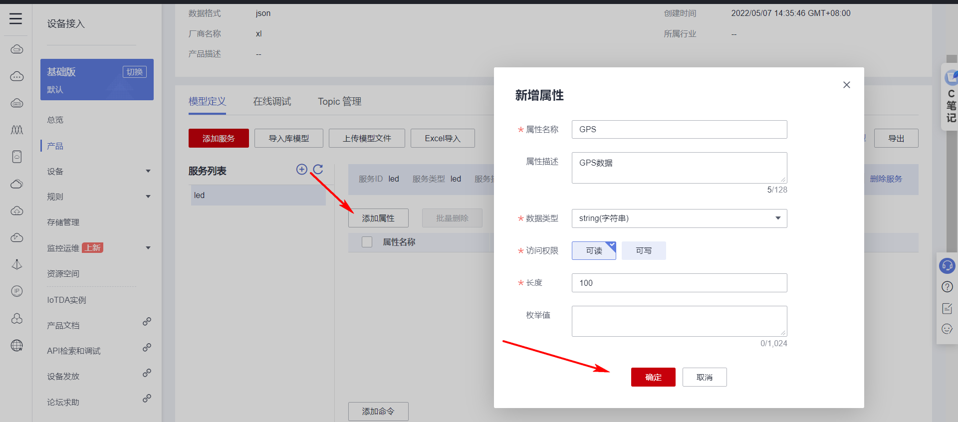
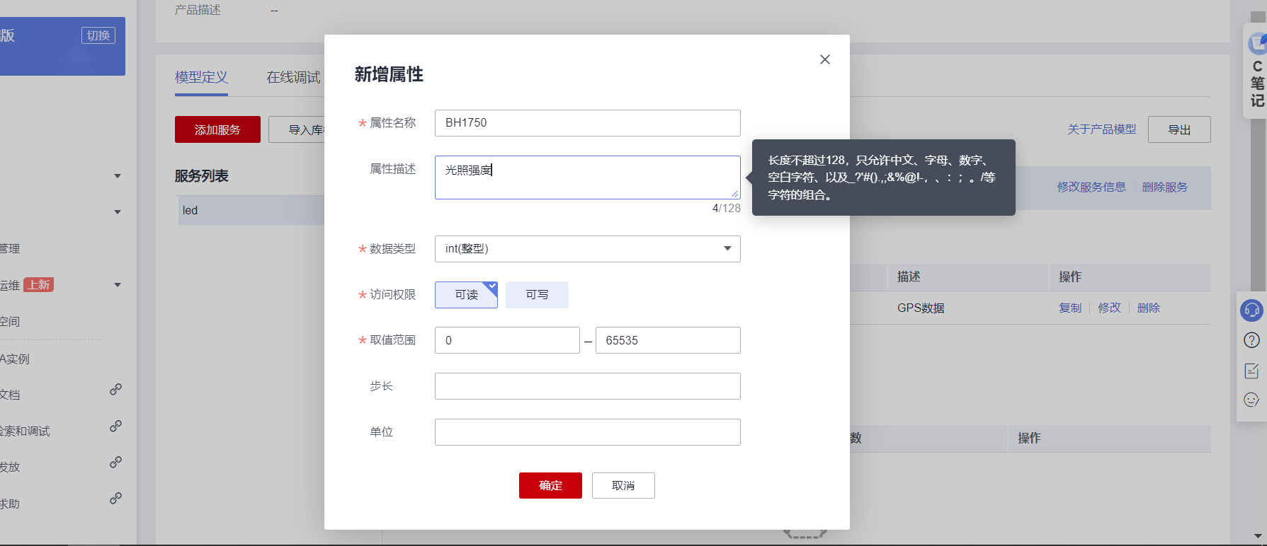
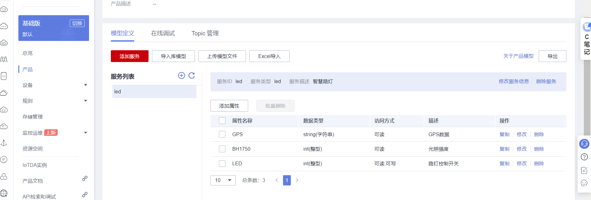
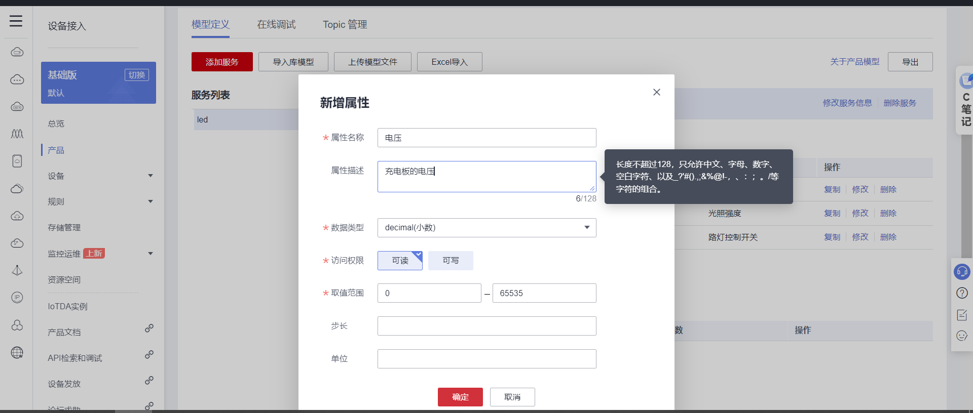
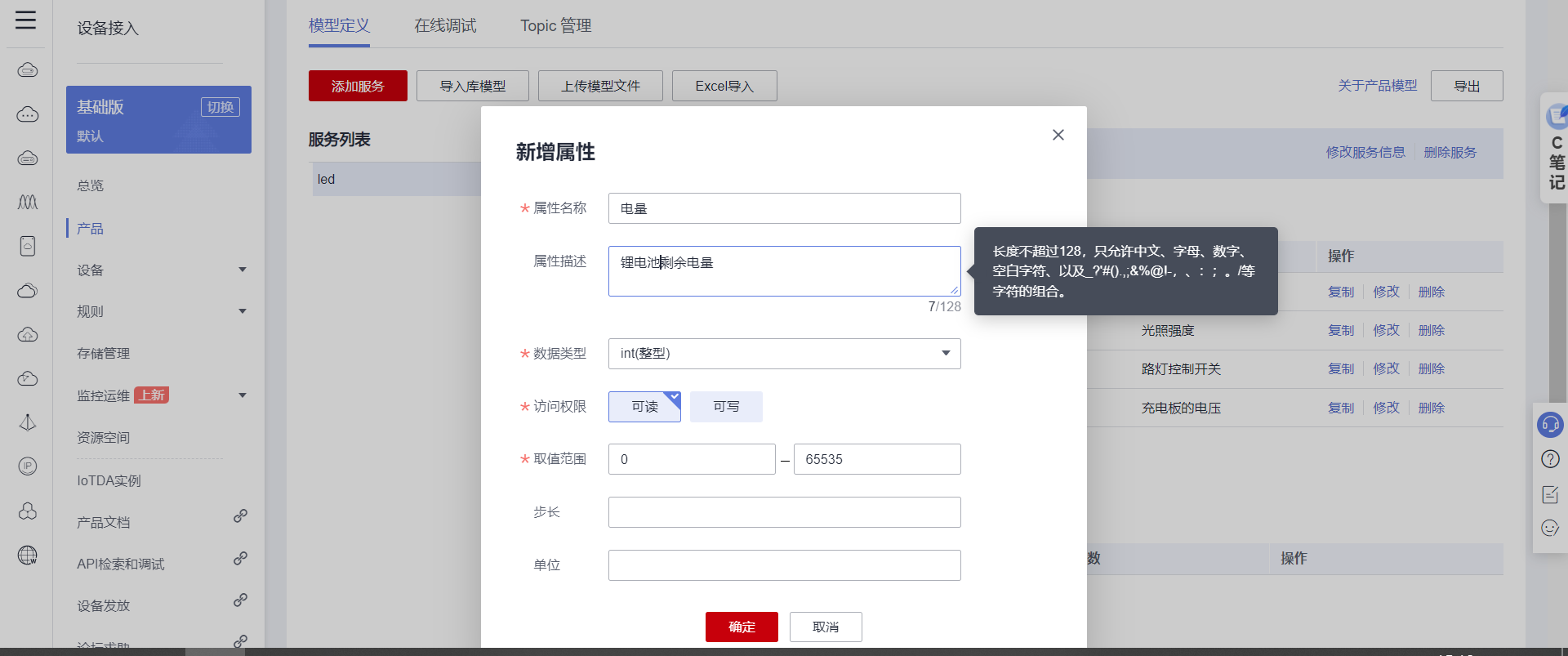
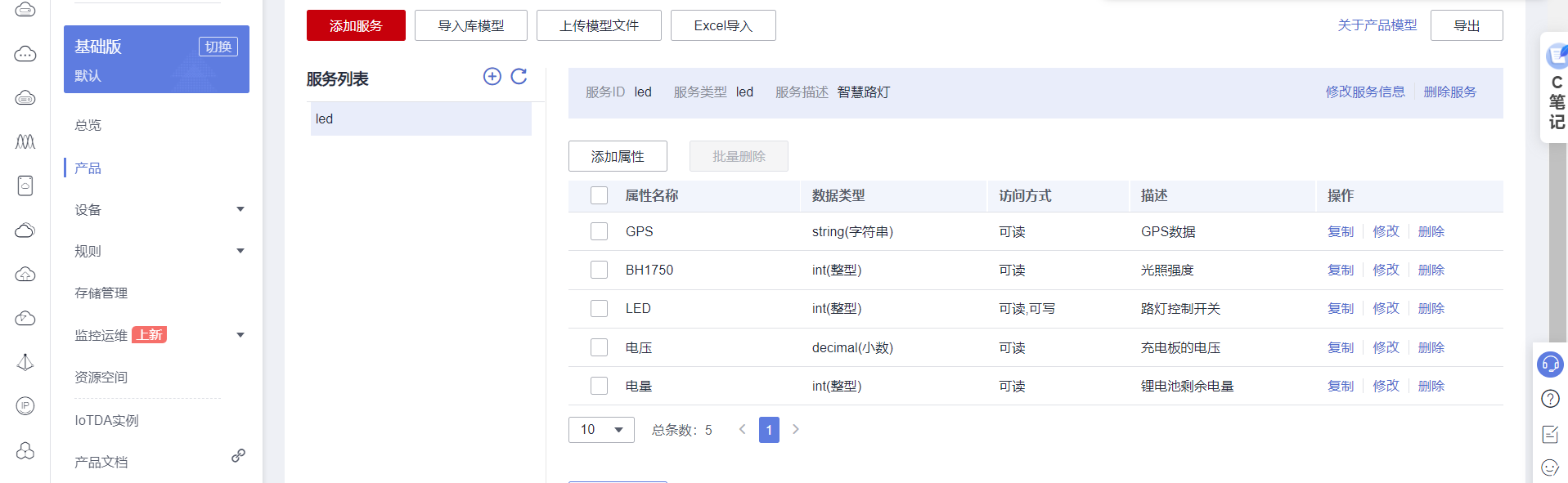
4.2 Custom model
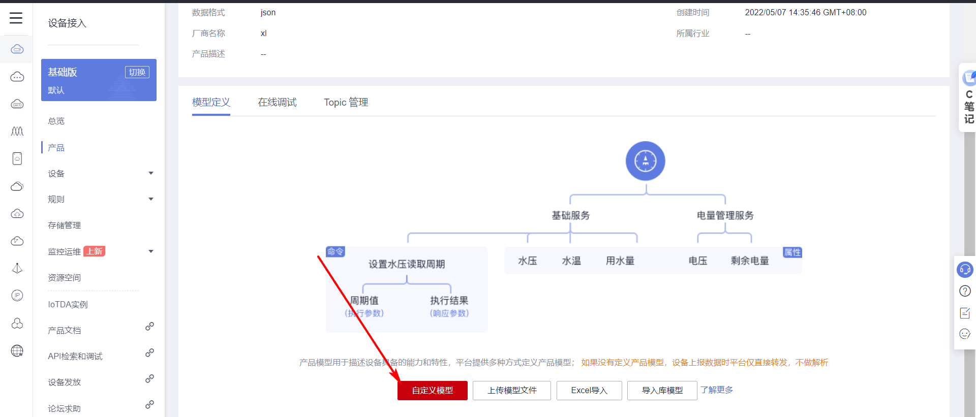
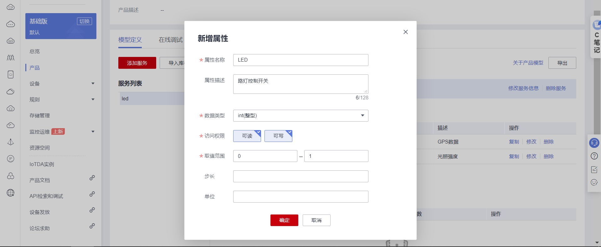
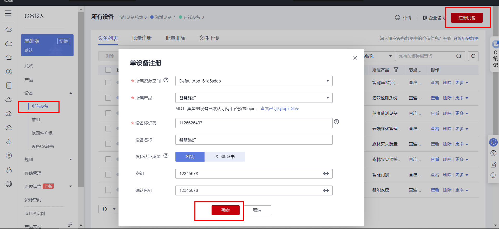
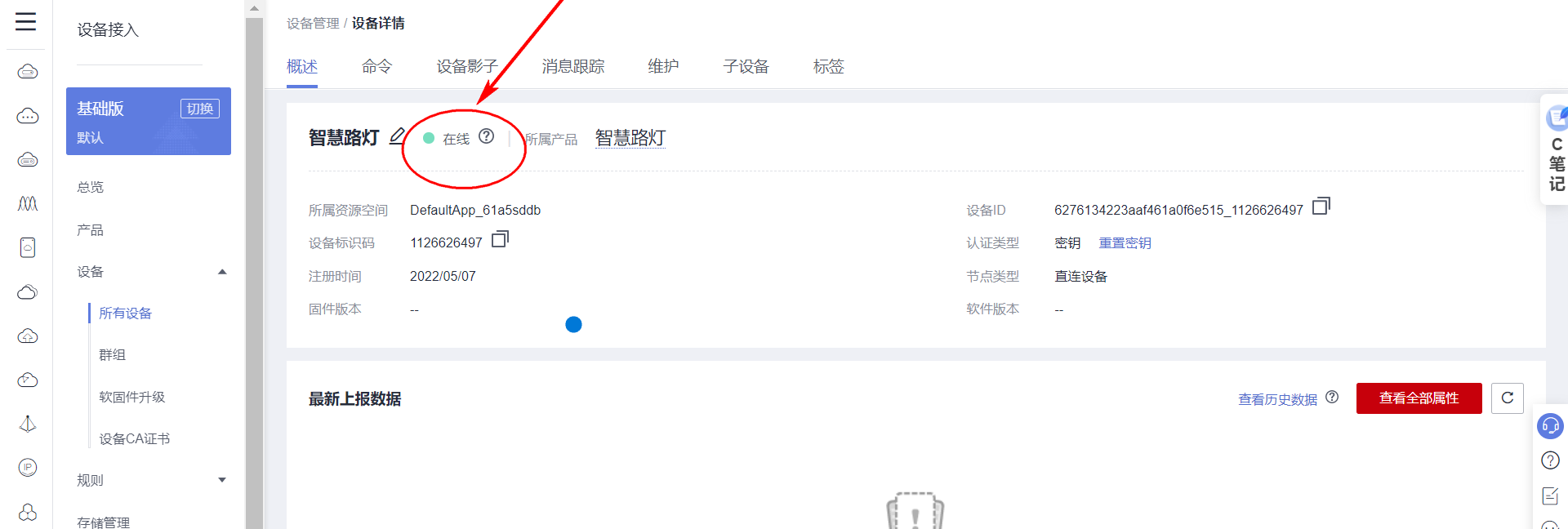
4.3 Create device
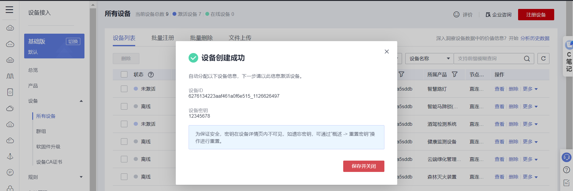
{
 "device_id": "6276134223aaf461a0f6e515_1126626497",
 "secret": "12345678"
}
4.4 MQTT Key generation
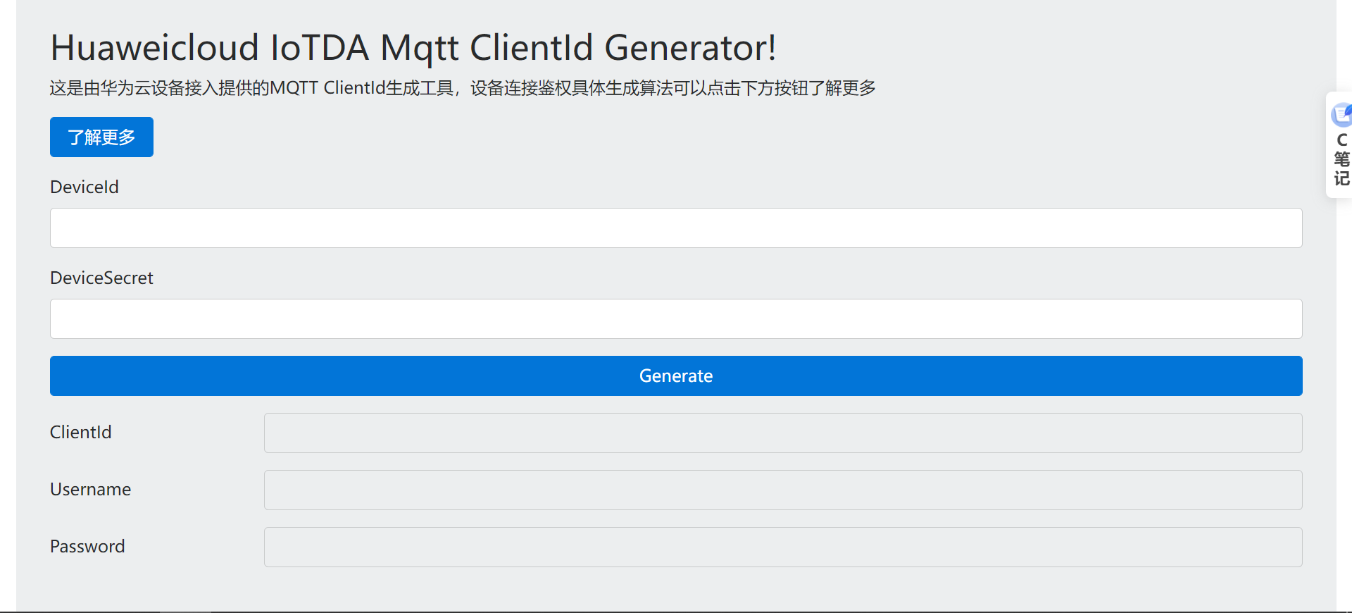
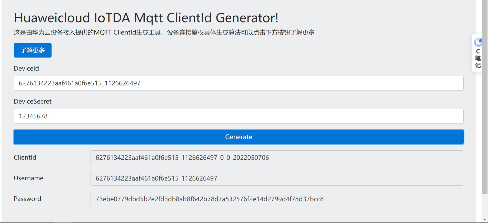
DeviceId 6276134223aaf461a0f6e515_1126626497
DeviceSecret 12345678
ClientId 6276134223aaf461a0f6e515_1126626497_0_0_2022050706
Username 6276134223aaf461a0f6e515_1126626497
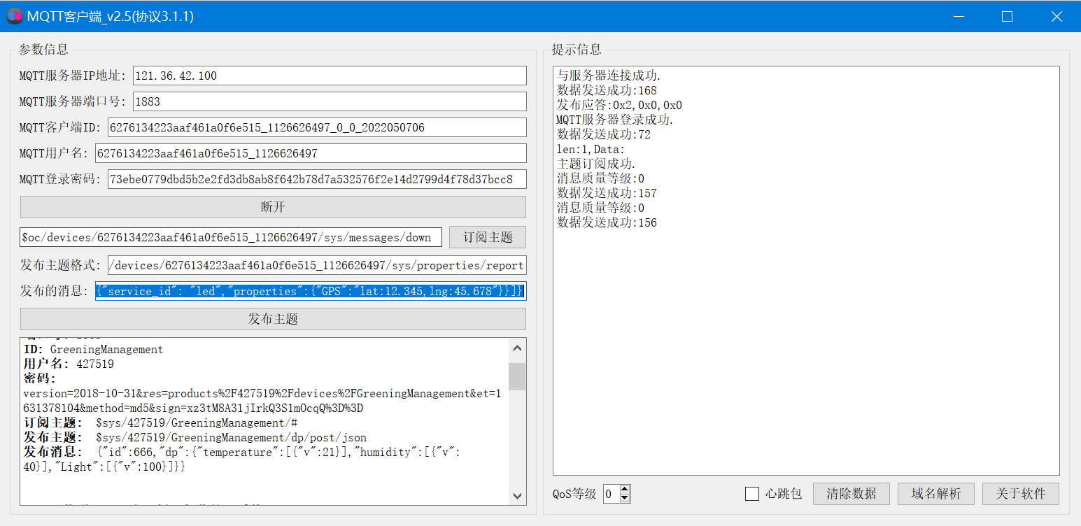
Password 73ebe0779dbd5b2e2fd3db8ab8f642b78d7a532576f2e14d2799d4f78d37bcc8
161a58a78.iot-mqtts.cn-north-4.myhuaweicloud.com121.36.42.100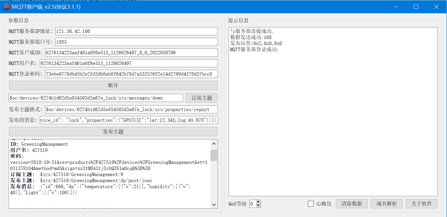
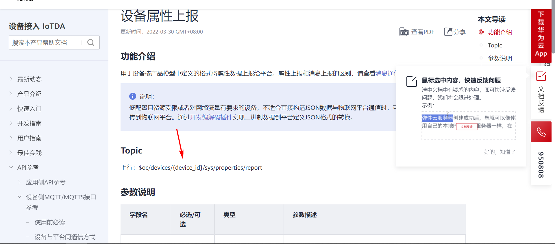
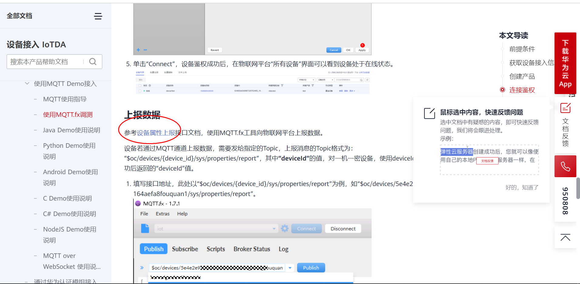
4.5 Topic subscription and Publishing
// Subscribe to topics :  The platform sends a message to the device
$oc/devices/6276134223aaf461a0f6e515_1126626497/sys/messages/down
// Equipment report data
$oc/devices/6276134223aaf461a0f6e515_1126626497/sys/properties/report
// Reported attribute message  ( Multiple attributes can be reported at a time , stay json Just add it to the )
{"services": [{"service_id": "led","properties":{"GPS":"lat:12.345,lng:45.678"}}]}
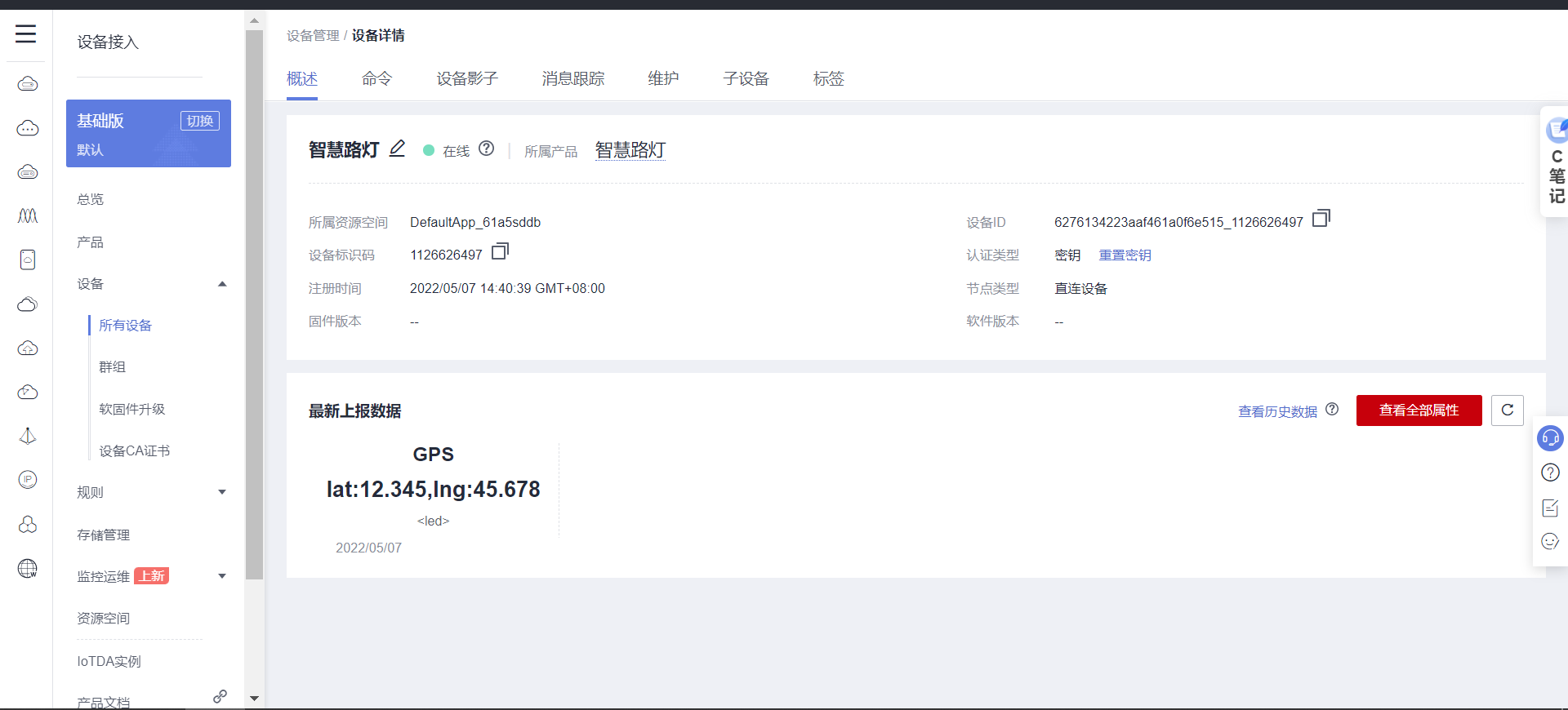
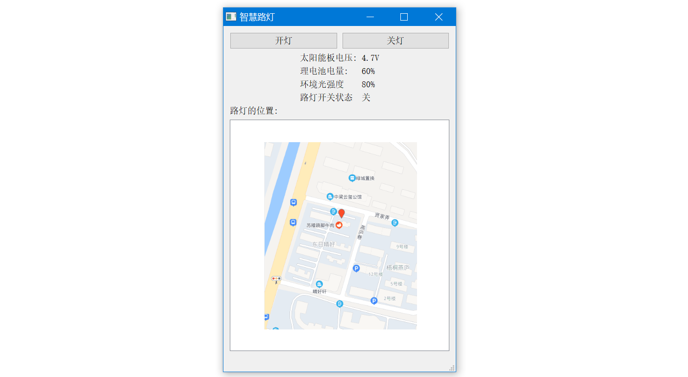
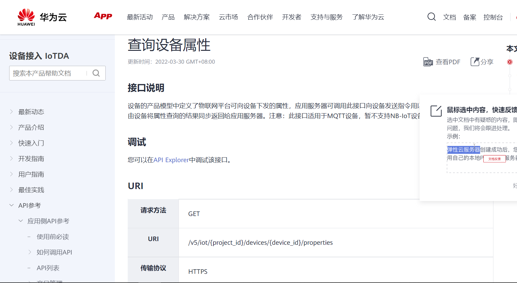
4.6 Application side development
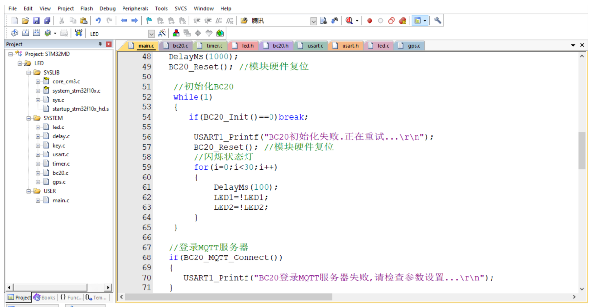
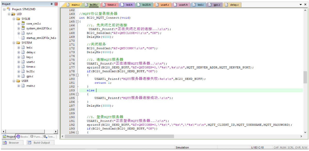
5. STM32 Programming
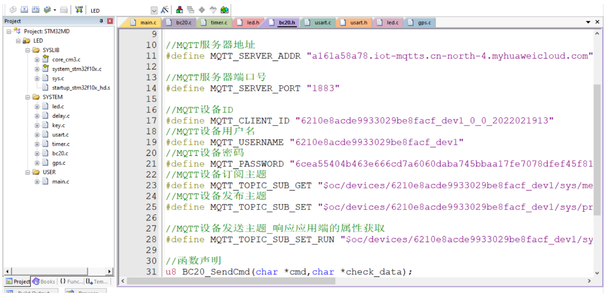
5.1 BC20 Connect Huawei cloud Internet of things server - debugging
Connect MQTT The server
AT+QMTOPEN=0,"a161a58a78.iot-mqtts.cn-north-4.myhuaweicloud.com",1883
OK
+QMTOPEN: 0,0
Sign in MQTT The server
Command format : AT+QMTCONN=<tcpconnectID>,<clientID>,<username>,<password>
AT+QMTCONN=0,"6210e8acde9933029be8facf_dev1_0_0_2022021913","6210e8acde9933029be8facf_dev1","6cea55404b463e666cd7a6060daba745bbaa17fe7078dfef45f8151cdf19673d"
OK
+QMTCONN: 0,0,0
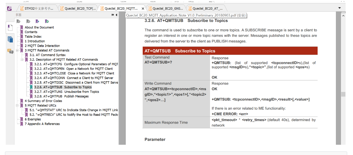
Subscribe to topics
Command format : AT+QMTSUB=<tcpconnectID>,<msgID>,"<topic1>”,<qos1>[,"<topic2>”,<qos2>…]
AT+QMTSUB=0,1,"$oc/devices/6210e8acde9933029be8facf_dev1/sys/messages/down",2
OK
+QMTSUB: 0,1,0,2
Release theme
Command format :AT+QMTPUB=<tcpconnectID>,<msgID>,<qos>,<retain>,"<topic>","<msg>"
Send instructions first :
AT+QMTPUB=0,0,0,0,"$oc/devices/6210e8acde9933029be8facf_dev1/sys/properties/repor"
Waiting to return ">"
And then send the data . You don't need to return the car .
"{"services": [{"service_id": "gps","properties":{"longitude":12.345,"latitude":33.345}}]}"
Data sent , Then send the Terminator . Hexadecimal value --0x1a . Some serial debugging assistants can adapt to ctrl+z Shortcut key input 0xA
Wait for the module to return "OK", This data transmission is complete .
OK
+QMTPUB: 0,0,0
5.2 Test module
ATOK Check whether the module is normal
AT
OK
Get the card number , Check whether the card is inserted properly
AT+CIMI
460041052911195
OK
Activate the network
AT+CGATT=1
OK
Get network activation status
AT+CGATT?
+CGATT: 1
OK
Query network quality
AT+CSQ
+CSQ: 26,0
OK
AT+CEREG=? // Check network status
+CEREG: 0,1 // Find network successfully
OK
5.3 keil Project code
5.4 Power detection
#include "INA226.h"
#include "delay.h"
//  Wiring instructions :
//  simulation IIC:
//IIC_SCL --  Clock line PB6( push-pull 、 Open drain output )
//IIC_SDA --  Two way data line PB7
INA226 ina226_data;
// initialization INA226
void INA226_Init(void)
{

 IIC_Init();
 INA226_SendData(INA226_ADDR1,CFG_REG,0x8000); // Restart

 INA226_SendData(INA226_ADDR1,CFG_REG,0x484f); // Set the conversion time 204us, The average number of times 128, The sampling time is 204*128, Set the mode to shunt and bus continuous mode
 INA226_SendData(INA226_ADDR1,CAL_REG,CAL); // Set resolution
 //INA226_SendData(INA226_ADDR1,CAL_REG,0x0012);// Set shunt voltage to current conversion parameters
 INA226_Get_ID(INA226_ADDR1); // obtain ina226 Of id
}

// Set register pointer
void INA226_SetRegPointer(u8 addr,u8 reg)
{
 IIC_Start();

 IIC_Send_Byte(addr);
 IIC_Wait_Ack();

 IIC_Send_Byte(reg);
 IIC_Wait_Ack();

 IIC_Stop();
}

// send out , Write data
void INA226_SendData(u8 addr,u8 reg,u16 data)
{
 u8 temp=0;
 IIC_Start();

 IIC_Send_Byte(addr);
 IIC_Wait_Ack();

 IIC_Send_Byte(reg);
 IIC_Wait_Ack();

 temp = (u8)(data>>8);
 IIC_Send_Byte(temp);
 IIC_Wait_Ack();

 temp = (u8)(data&0x00FF);
 IIC_Send_Byte(temp);
 IIC_Wait_Ack();

 IIC_Stop();
}

// Reading data
u16 INA226_ReadData(u8 addr)
{
 u16 temp=0;
 IIC_Start();

 IIC_Send_Byte(addr+1);
 IIC_Wait_Ack();

 temp = IIC_Read_Byte(1);
 temp<<=8;
 temp |= IIC_Read_Byte(0);

 IIC_Stop();
 return temp;
}
//1mA/bit
u16 INA226_GetShunt_Current(u8 addr)
{
 u16 temp=0;
 INA226_SetRegPointer(addr,CUR_REG);
 temp = INA226_ReadData(addr);
 if(temp&0x8000) temp = ~(temp - 1);
 return temp;
}

// obtain id
void INA226_Get_ID(u8 addr)
{
 u32 temp=0;
 INA226_SetRegPointer(addr,INA226_GET_ADDR);
 temp = INA226_ReadData(addr);
 ina226_data.ina226_id = temp;
}

// Obtain the calibration value
u16 INA226_GET_CAL_REG(u8 addr)
{
 u32 temp=0;
 INA226_SetRegPointer(addr,CAL_REG);
 temp = INA226_ReadData(addr);
 return (u16)temp;
}

//1.25mV/bit
u16 INA226_GetVoltage(u8 addr)
{
 u32 temp = 0;
 INA226_SetRegPointer(addr,BV_REG);
 temp = INA226_ReadData(addr);
 return (u16)temp;
}

//2.5uV/bit
u16 INA226_GetShuntVoltage(u8 addr)
{
 int16_t temp = 0;
 INA226_SetRegPointer(addr,SV_REG);
 temp = INA226_ReadData(addr);
 if(temp&0x8000) temp = ~(temp - 1);
 return (u16)temp;
}

// Get the voltage
void GetVoltage(float *Voltage)//mV
{
 *Voltage = INA226_GetVoltage(INA226_ADDR1)*Voltage_LSB;
}

// Obtain shunt voltage
void Get_Shunt_voltage(float *Voltage)//uV
{
 *Voltage = (INA226_GetShuntVoltage(INA226_ADDR1)*INA226_VAL_LSB);// To correct the current shunt parameters, please change this to 2.5
}

// Get current
void Get_Shunt_Current(float *Current)//mA
{
 *Current = (INA226_GetShunt_Current(INA226_ADDR1)* CURRENT_LSB);
}

// Get power =  Bus voltage  *  electric current
void get_power()//W
{
 GetVoltage(&ina226_data.voltageVal); //mV
 Get_Shunt_voltage(&ina226_data.Shunt_voltage); //uV
 Get_Shunt_Current(&ina226_data.Shunt_Current); //mA
 Get_Power(&ina226_data.Power);
 ina226_data.Power_Val = ina226_data.voltageVal*0.001f * ina226_data.Shunt_Current*0.001f; //mV*mA
}

// Get the power loading value ,ina226 Internally calculated power , Because it is not calibrated , So... Is not used

u16 INA226_Get_Power(u8 addr)
{
 int16_t temp=0;
 INA226_SetRegPointer(addr,PWR_REG);
 temp = INA226_ReadData(addr);
 return (u16)temp;
}

// Get power ,ina226 Internal calculation , inaccurate , Do not use
void Get_Power(float *Power)//W
{
 *Power = (INA226_Get_Power(INA226_ADDR1)*POWER_LSB);
}

// No alarm is set , Abandon
/*
u8 INA226_AlertAddr()
{
 u8 temp;
 IIC_Start();

 IIC_Send_Byte(INA226_GETALADDR);
 IIC_Wait_Ack();

 temp = IIC_Read_Byte(1);

 IIC_Stop();
 return temp;
}
*/
5.5 BH1750 Ambient light intensity
#include "bh1750.h"
float Read_BH1750_Data()
{
 unsigned char t0;
 unsigned char t1;
 float t;
 u8 r_s=0;
 IIC_Start(); // Send the start signal
 IIC_WriteOneByteData(0x46);
 r_s=IIC_GetACK();// Get answers
 if(r_s)printf("error:1\r\n");
 IIC_WriteOneByteData(0x01);
 r_s=IIC_GetACK();// Get answers
 if(r_s)printf("error:2\r\n");
 IIC_Stop(); // Stop signal

 IIC_Start(); // Send the start signal
 IIC_WriteOneByteData(0x46);
 r_s=IIC_GetACK();// Get answers
 if(r_s)printf("error:3\r\n");
 IIC_WriteOneByteData(0x01);
 r_s=IIC_GetACK();// Get answers
 if(r_s)printf("error:4\r\n");
 IIC_Stop(); // Stop signal

 IIC_Start(); // Send the start signal
 IIC_WriteOneByteData(0x46);
 r_s=IIC_GetACK();// Get answers
 if(r_s)printf("error:5\r\n");
 IIC_WriteOneByteData(0x10);
 r_s=IIC_GetACK();// Get answers
 if(r_s)printf("error:6\r\n");
 IIC_Stop(); // Stop signal

 DelayMs(100); // wait for

 IIC_Start(); // Send the start signal
 IIC_WriteOneByteData(0x47);
 r_s=IIC_GetACK();// Get answers
 if(r_s)printf("error:7\r\n");

 t0=IIC_ReadOneByteData(); // receive data
 IIC_SendACK(0); // Send reply signal
 t1=IIC_ReadOneByteData(); // receive data
 IIC_SendACK(1); // Send non reply signal
 IIC_Stop(); // Stop signal

 t=(((t0<<8)|t1)/1.2);
 return t;
}
边栏推荐
- pip install pyodbc : ERROR: Command errored out with exit status 1
- 【MySQL入门】第四话 · 和kiko一起探索MySQL中的运算符
- Interpretation of Flink source code (II): Interpretation of jobgraph source code
- [getting started with MySQL] fourth, explore operators in MySQL with Kiko
- Hongmeng introduction and development environment construction
- Debug and run the first xv6 program
- Flink analysis (II): analysis of backpressure mechanism
- Compile and build, from the bottom to the top
- 06 products and promotion developed by individuals - code statistical tools
- TCP connection is more than communicating with TCP protocol
猜你喜欢
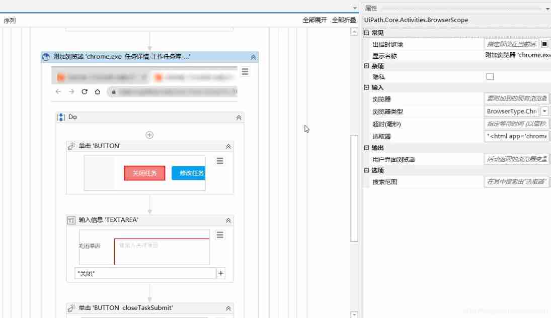
Uipath browser performs actions in the new tab
![[rapid environment construction] openharmony 10 minute tutorial (cub pie)](/img/b5/feb9c56a65c3b07403710e23078a6f.jpg)
[rapid environment construction] openharmony 10 minute tutorial (cub pie)
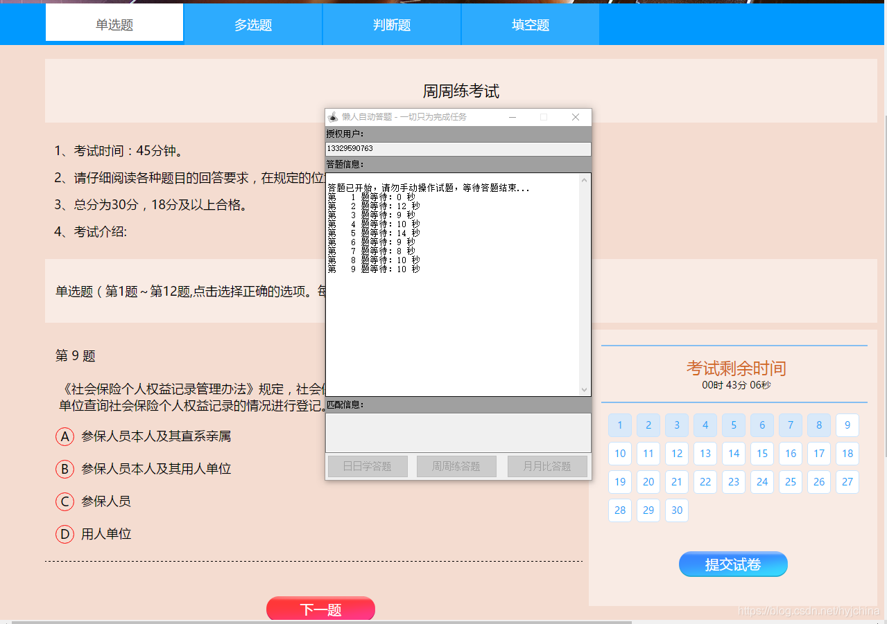
Selenium test of automatic answer runs directly in the browser, just like real users.
Distributed (consistency protocol) leader election (dotnext.net.cluster implements raft election)
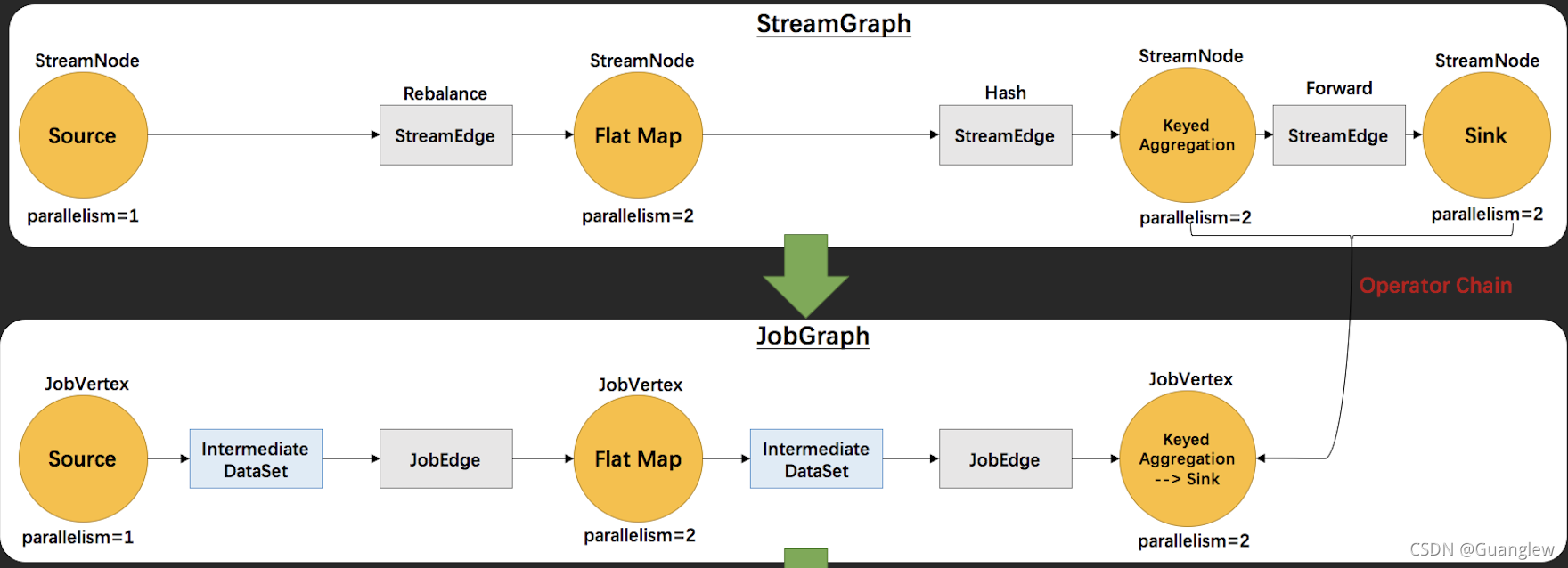
Interpretation of Flink source code (II): Interpretation of jobgraph source code
FlutterWeb浏览器刷新后无法回退的解决方案

Unity小技巧 - 绘制瞄准准心
分布式不来点网关都说不过去
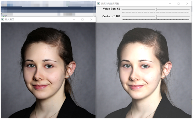
How to use scroll bars to dynamically adjust parameters in opencv
In terms of byte measurement with an annual salary of 30W, automated testing can be learned in this way
随机推荐
Establishment of graphical monitoring grafana
Shell input a string of numbers to determine whether it is a mobile phone number
Debug and run the first xv6 program
SQL statement optimization, order by desc speed optimization
OpenCV中如何使用滚动条动态调整参数
The NTFS format converter (convert.exe) is missing from the current system
The art of Engineering
EasyCVR平台通过接口编辑通道出现报错“ID不能为空”,是什么原因?
学 SQL 必须了解的 10 个高级概念
Solrcloud related commands
PySpark算子处理空间数据全解析(4): 先说说空间运算
Quick start of Hongmeng system
Kernel link script parsing
07 personal R & D products and promotion - human resources information management system
Application service configurator (regular, database backup, file backup, remote backup)
Hongmeng introduction and development environment construction
[elastic] elastic lacks xpack and cannot create template unknown setting index lifecycle. name index. lifecycle. rollover_ alias
10 advanced concepts that must be understood in learning SQL
Wechat applet obtains mobile number
中移动、蚂蚁、顺丰、兴盛优选技术专家,带你了解架构稳定性保障