当前位置:网站首页>Detailed software engineering -- the necessary graphs in each stage
Detailed software engineering -- the necessary graphs in each stage
2020-11-06 21:55:00 【Prosperity 3000】
Detailed software engineering ---- The graphs that are essential for each stage
Reprint https://my.oschina.net/u/3464538/blog/4491696
One 、 Preface
In Software Engineering , Software life cycle is defined by software 、 Software development and operation maintenance ( Also known as software maintenance )3 Periods make up , Each period is further divided into several stages .
-
Software definition period includes problem definition 、 feasibility study 、 There are three stages of requirement analysis .
-
The software development period includes the overall design 、 Detailed design 、 Coding and unit testing 、 There are four stages of comprehensive test .
-
The software maintenance period only includes the software maintenance stage .
The purpose of this paper is to illustrate the meaning and use of various graphs in different stages of the software life cycle .
Two 、 feasibility study
2.1 System flow chart
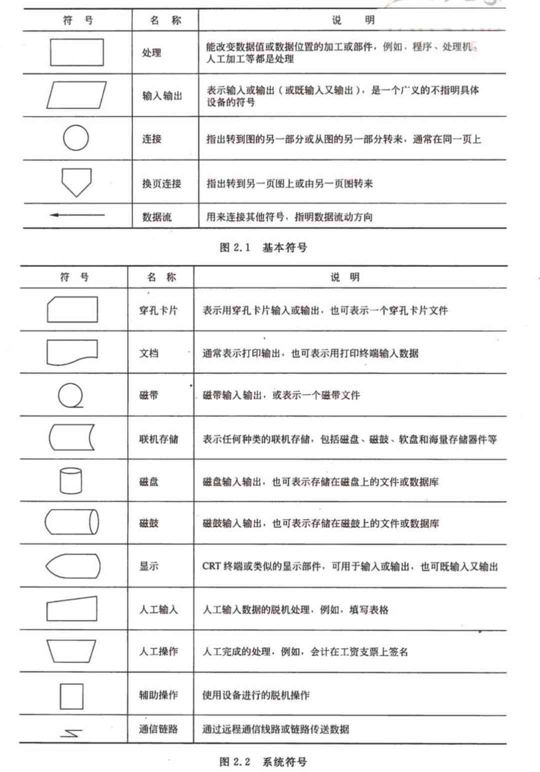
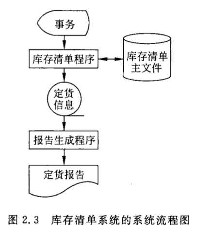
System flow chart is a traditional tool to describe physical system generally . Its basic idea is to use graphic symbols to describe every component of the system in the form of black boxes ( Program 、 file 、 database 、 Artificial process, etc ). The flow of data between system components represented by system flow chart , Not the control process of processing data , Therefore, although some symbols of system flow chart and program flow chart have the same symbol form , But it's a physical data flow diagram, not a program flow diagram .
Symbol
When describing an actual system abstractly in a general way , Just use the diagram 2.1 The basic symbols listed in are enough . When you need to describe a physical system more specifically, you also need to use diagrams 2.2 System symbols listed in , With these symbols, a generalized I / O operation can be embodied as reading and writing files stored on special devices ( Or database ), Materialize abstract processing into specific procedures or manual operations .
usage
Example
layered
In the face of complex systems , A better way is to describe the system at different levels . First, use a high-level system flow chart to describe the overall picture of the system , Show the key functions of the system . Then extend each key function to the appropriate level of detail , Draw on a separate sheet of paper . This hierarchical description method is convenient for readers to understand a complex system step by step according to the process from abstract to concrete .
2.2 Data flow diagram
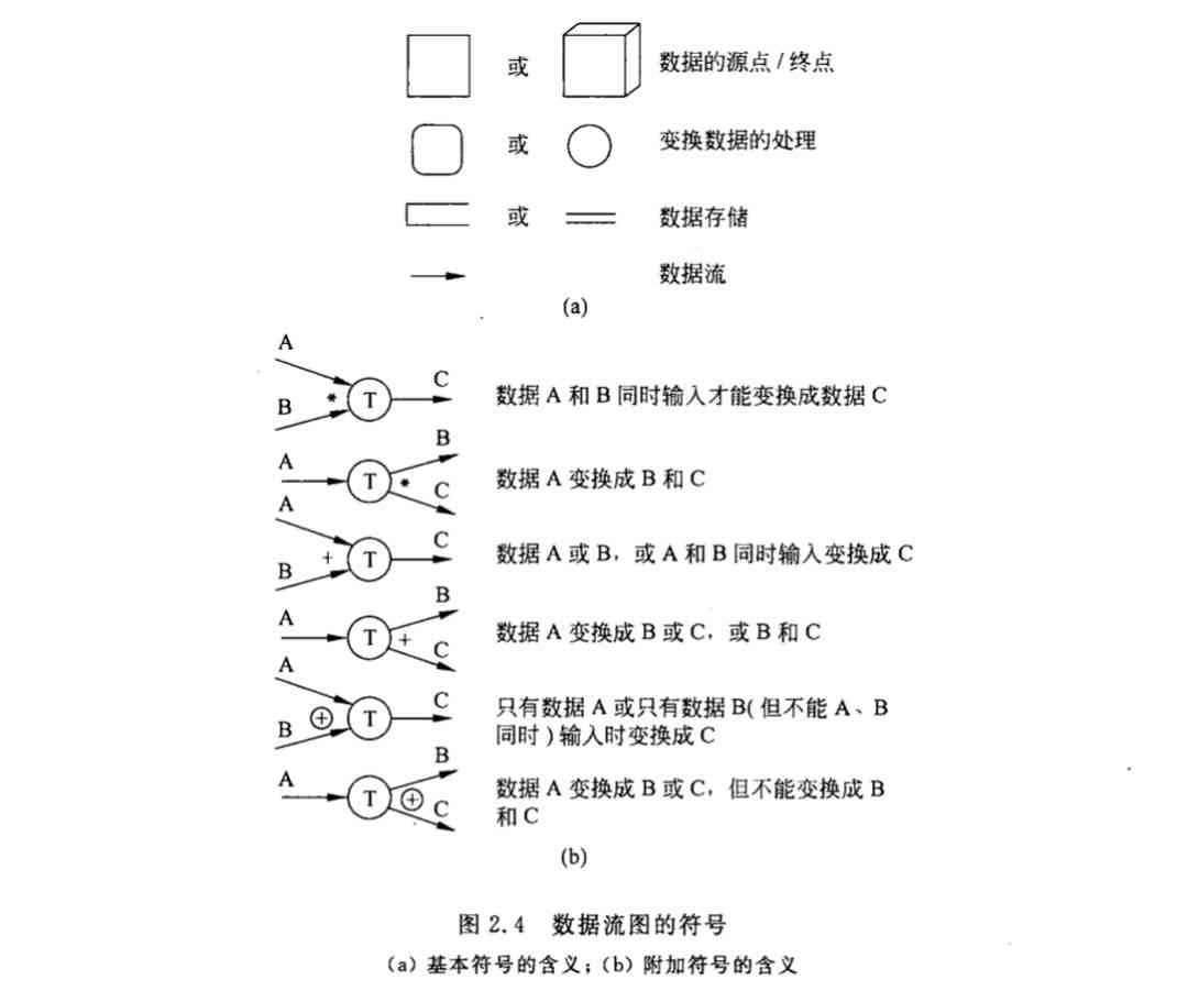
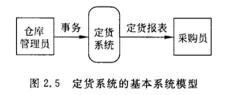
Data flow diagram (DFD) It's a kind of graphic technology , It depicts the transformation of information flow and data from input to output . There are no specific physical components in the data flow diagram , It just describes the logical process of data flowing and being processed in software . Data flow diagram is a graphic representation of system logic functions , Even if it's not a professional computer technician, it's easy to understand , So it's an excellent communication tool between analysts and users . Besides , When designing the data flow diagram, only the basic logic functions that the system must complete need to be considered , There is no need to consider how to implement these functions , So it is also a good starting point for software design in the future .
Symbol
Example
3、 ... and 、 Demand analysis
3.1 Entity - Contact diagram
In order to make the user's data requirements clear 、 Describe exactly , System analysts usually build a conceptual data model ( Also known as the information model ). Conceptual data model is a problem oriented data model , It's a model of data from the user's point of view . It describes the data seen from the user's point of view , It reflects the user's real environment , And it has nothing to do with the implementation method in the software system . The data model contains 3 Kind of interrelated information : Data objects 、 The properties of data objects and the relationship between data objects and each other .
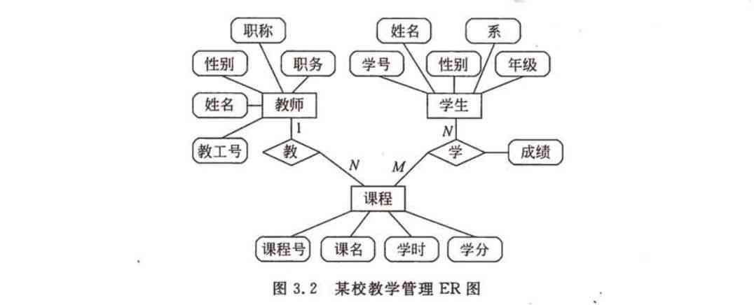
Usually , Use entity - Contact diagram (entity-relationship diagram) To build a data model . You can put the entity - The contact diagram is abbreviated as ER chart , Use accordingly ER The data model depicted in the figure is called ER Model .
Symbol
ER The figure contains the entity 、 Relationships and attributes 3 Basic ingredients , Usually a rectangular box is used to represent an entity , Use a diamond box to connect related entities to represent the relationship , Use ellipses or rounded rectangles to represent entities ( Or relationship ) Properties of , And use a straight line to put the entity ( Or relationship ) Connect with its attributes .
Example
3.2 State transition diagram
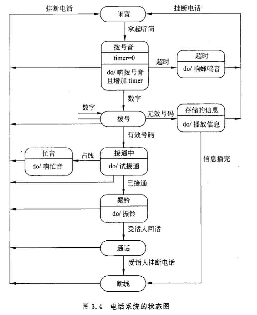
In the process of requirement analysis, the behavior model of software system should be established . State transition diagram ( It's called state diagram for short ) By describing the state of the system and the events that cause the state transition of the system , To represent the behavior of the system . Besides , The state diagram also indicates what the system will do as a result of a particular event ( for example , Processing data ).
state
State is any system behavior pattern that can be observed , A state represents a pattern of behavior of a system . State specifies how the system responds to events . System response to events , You can make a ( Or a series of ) action , Or just changing the state of the system itself , It can also be changing state and doing actions .
The states defined in the state diagram are mainly : Initial state ( The initial state )、 Terminal state ( The final state ) And the intermediate state . There can only be one initial state in a state diagram , And the final state can have 0 At most .
The state diagram can not only represent the cycle operation process of the system , It can also represent the one-way life cycle of the system . When describing the cycle operation process , It doesn't usually matter how the loop starts . When describing a one-way life cycle , The initial state... Needs to be indicated ( Enter the initial state when the system starts ) And final status ( The system reaches the final state at the end of operation ).
event
An event is something that happens at a certain time , It's about acting on the causing system or ( and ) The abstraction of an external event from one state to another . for example , An internal clock indicates that a specified period of time has passed , The user moves or clicks the mouse and so on are the events . In short , An event is something that causes the system to act or ( and ) Control information of transition state .
Symbol
In the state diagram , The initial state is represented by a solid circle , The final state is a pair of concentric circles ( The inner circle is a solid circle ) Express . The middle state is represented by rounded rectangle , It can be divided into two horizontal lines 、 in 、 Next 3 Parts of . The above part is the name of the State , This part is necessary ; The middle part is the name and value of the state variable , This part is optional ; The following part is the activity list , This part is also optional .
The syntax format of the activity table is as follows :
Event name ( Parameter table )/ Action expression
among ,“ Event name ” It can be the name of any event . The following are often used in the activity list 3 Standard events :entry,exit and do.entry Event specifies the action to enter the state ,exit Event specifies the action to exit the state , and do Event specifies the action in this state . You can specify a parameter table for the event if necessary . The action expression in the activity table describes the specific action to be done .
The line with arrows between two states in the state diagram is called state transition , The arrow indicates the direction of change . State transitions are usually triggered by events , In this case, the event expression that triggers the transition shall be marked on the arrow line representing the state transition ; If the event is not indicated on the arrow line , It means that the transition will be triggered automatically after the internal activity of the source state is executed .
The syntax of the event expression is as follows :
Event description [ Guard conditions ] / Action expression
among , The syntax of the event description is : Event name ( Parameter table ).
The guard condition is a Boolean expression . If you use both event description and guard conditions , If and only if the event occurs and the Boolean expression is true , It's a state transition . If only the guard condition has no event description , As long as the guard condition is true , State transition happens .
An action expression is a process expression , Execute this expression when the state transition starts .
chart 3.3 The main symbols used in the state diagram are given .

Example
3.3 Hierarchical block diagram
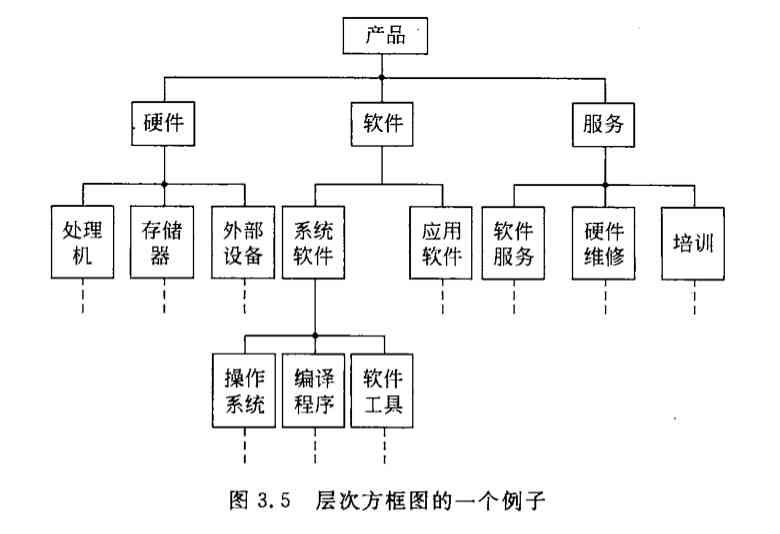
Hierarchical block diagram describes the hierarchical structure of data with a series of multi-level rectangular boxes in tree structure . The top layer of the tree structure is a separate rectangular box , It represents the complete data structure , The following layers of rectangles represent a subset of this data , The bottom boxes represent the actual data elements that make up the data ( Elements that can no longer be divided ).
Example
3.4 Warnier chart
French computer scientist Warnier Another graphic tool for representing information hierarchy is proposed — Warnier chart . Similar to the hierarchical block diagram ,Warnier The picture also uses tree structure to describe information , But this kind of graphic tool provides more abundant description means than the hierarchical block diagram .
use Warnier Diagram can show the logical organization of information , in other words , It can point out that a kind of information or an information element is repeated , It can also indicate that specific information appears conditionally in a certain kind of information . Because repetition and conditionality are the basis of software processing , So it's easy to put Warnier Figure into software design tools .
Example
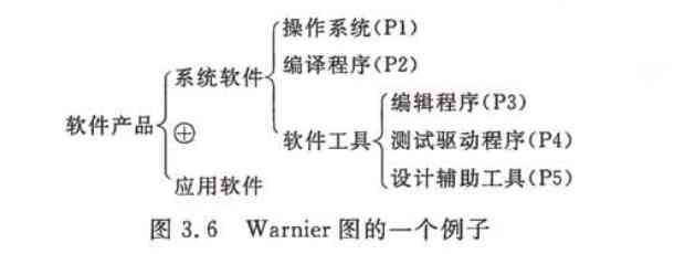
The curly brackets in the figure are used to distinguish the hierarchy of data structure , All names in a curly bracket belong to the same kind of information ; different Or symbols (⊕) Indicates that a type of information or a data element only appears under certain conditions , And on this symbol 、 below The data represented by two names of can only appear one ; Under a name ( Or to the right ) The numbers in parentheses indicate the information class represented by this name ( Or elements ) The number of repetitions in this data structure .( for example P1 Kind of 、 P2 Kind of )
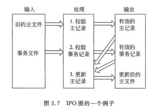
3.5 IPO chart
IPO Figure is input 、 Handle 、 The abbreviation of the output graph , It was made by the United States IBM A graphic tool developed by the company , Can easily describe the input data 、 The relationship between data processing and output data .
IPO The basic symbols used in graphs are few and simple , So it's easy to learn how to use this graphic tool . Its basic form is to list the relevant input data in the box on the left , List the main processes... In the middle box , List the output data generated in the box on the right . The order of processing listed in the processing box implies the order of execution , But these basic symbols are not enough to accurately describe the details of the execution process . stay IPO In the figure, a large arrow similar to the vector symbol is also used to clearly indicate the data communication situation .
Example
Four 、 overall design
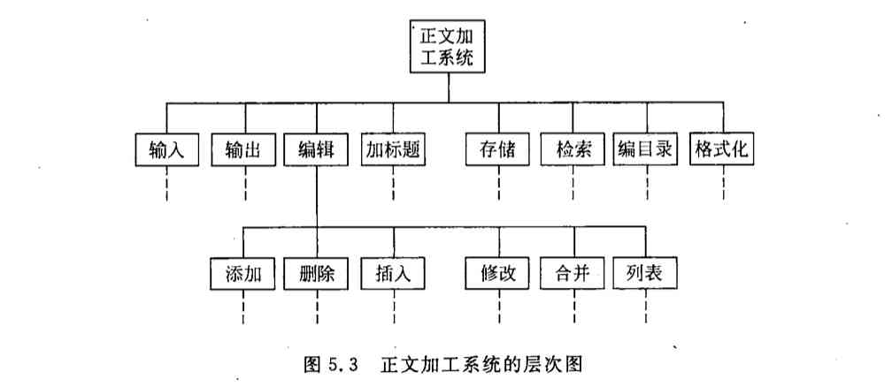
4.1 Hierarchical graph
A hierarchy is used to describe the hierarchical structure of software . A rectangular box in the hierarchy represents a module , The lines between the boxes indicate Call relationship It's not like the hierarchical block diagram Make up a relationship .
Example
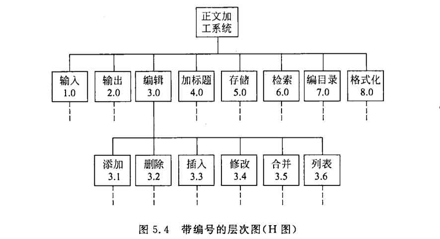
4.2 HIPO chart
HIPO The picture is America IBM Invented by the company “ Hierarchy plus input / Handle / Output chart ” English abbreviations . In order to make HIPO Graphs are traceable , stay H chart ( Hierarchical graph ) In addition to the top box , Each box is numbered .
Example
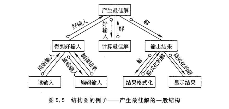
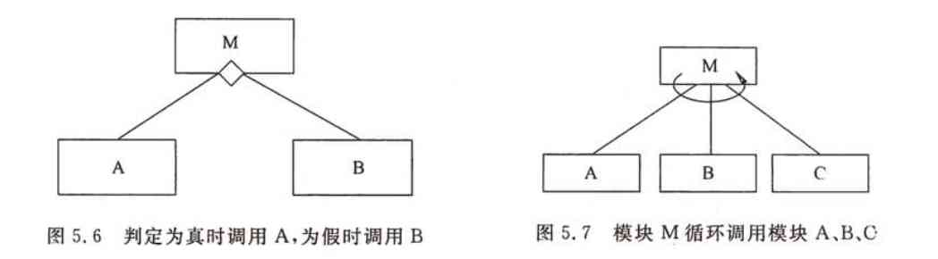
4.3 chart
Yourdon The structure diagram is another powerful tool for software structure design . The structure chart is similar to the hierarchy chart , It's also a graphic tool for describing software structure , A box in the figure represents a module , The name or main function of the module shall be indicated in the box ; The arrows between the boxes ( Or straight line ) Represents the calling relationship of the module .
In the structure diagram, the annotated arrows are usually used to represent the information passed back and forth during the module call . If you want to further indicate whether the information transmitted is data or control information , You can use the shape at the end of the comment arrow to distinguish : If the tail is a hollow circle, it means the data is transferred , A solid circle indicates that it is transmitting control information .
Example
5、 ... and 、 Detailed design
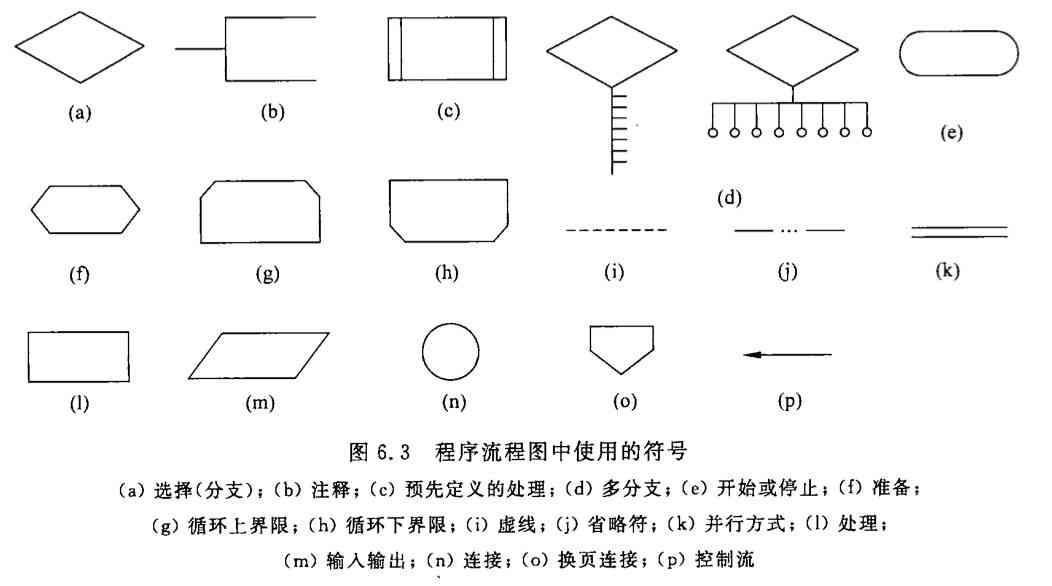
5.1 Program flow chart
Program flow chart is also called program block diagram , It has the longest history 、 The most widely used way to describe process design , But it's also one of the most confusing methods .
from 20 century 40 From the end of the decade to 70 The mid - , Program flow chart is always the main tool of software design . Its main advantage is that the description of the control process is very intuitive , Easy for beginners to master . Due to the long history of program flow chart , Familiar to the widest range of people , Despite all its shortcomings , Many people suggest that we stop using it , But it is still widely used . But the general trend is that more and more people are no longer using program flow charts .
The main disadvantages of program flow chart are as follows .
-
In essence, program flow chart is not a good tool for gradual refinement , It tempts the programmer to think about the control flow of the program too early , Without considering the overall structure of the program .
-
In the program flow chart, arrows are used to represent the control flow , So programmers don't have any constraints , We can ignore the spirit of structural programming , Transfer control at will .
-
Program flow chart is not easy to represent data structure .
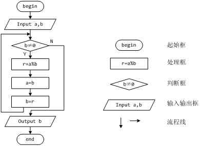
Symbol
Example
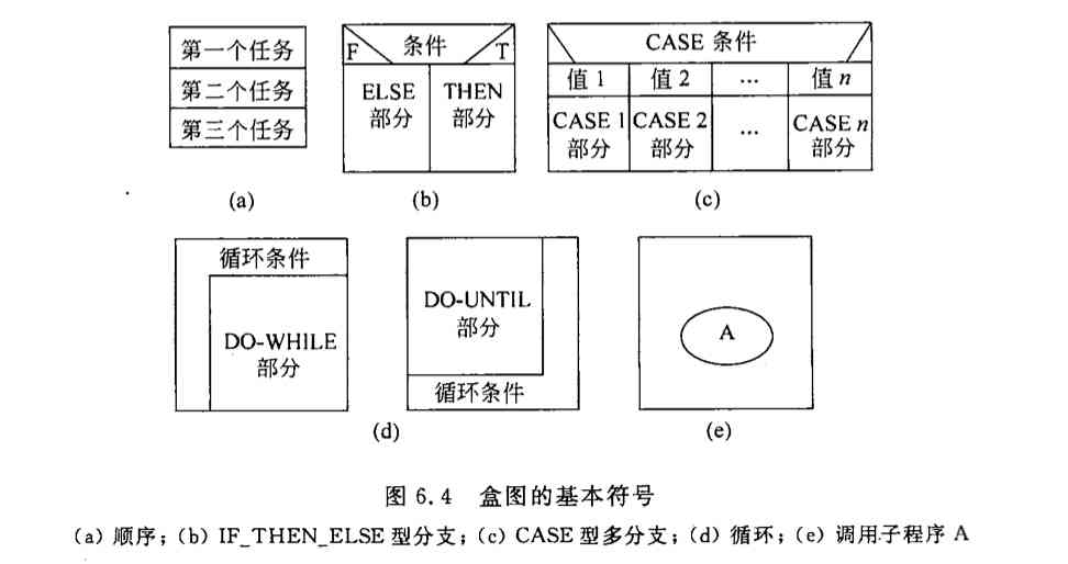
5.2 Box chart
In order to have a graphics tool that does not allow to violate the spirit of structural programming ,Nassi and Shneiderman Put forward the box diagram , Also known as N-S chart . It has the following characteristics .
-
Functional areas ( namely , The scope of a particular control structure ) clear , It can be seen at a glance from the box chart .
-
It is not possible to transfer control arbitrarily .
-
It's easy to determine the scope of local and full data .
-
It's easy to express nested relationships , It can also represent the hierarchy of modules .
Symbol
5.3 PAD chart
PAD The graph is the problem analysis graph (problem analysis diagram) English abbreviations , since 1973 Invented by Hitachi in , It has been popularized to a certain extent . It uses a two-dimensional tree structure to represent the control flow of the program , It's easier to translate this graph into program code .
Symbol
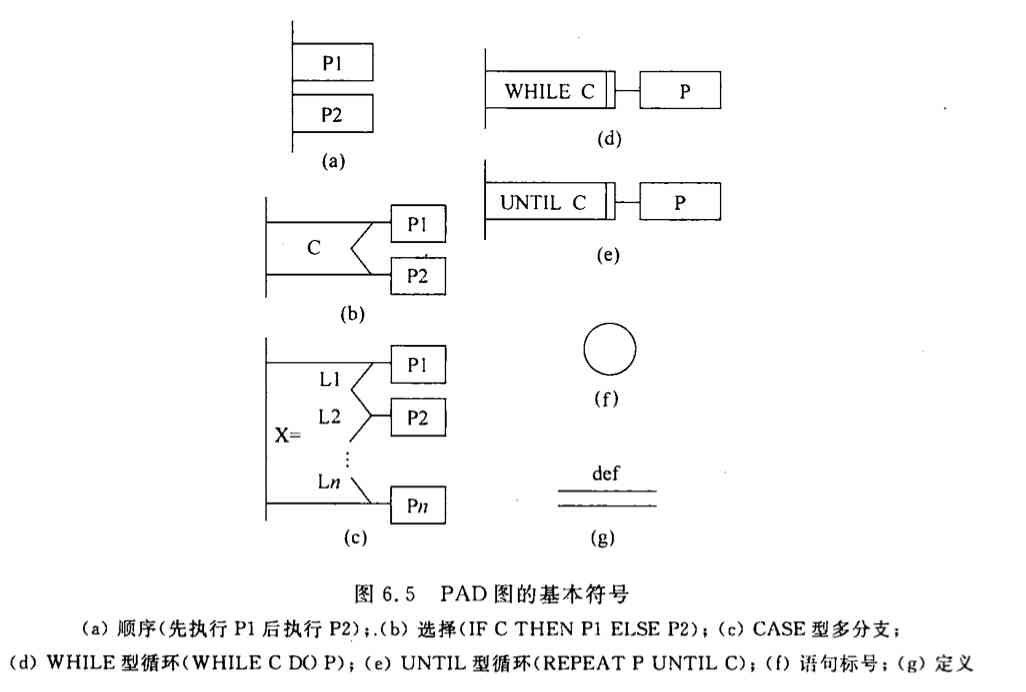
advantage
PAD The main advantages of the diagram are as follows :
-
Use... To represent a structured control structure PAD The program designed by symbols must be structured program .
-
PAD The program structure depicted in the figure is very clear . The vertical line on the left is the main line of the program , That is, the first layer structure . With the increase of program level ,PAD The picture gradually extends to the right , Every time you add a level , The graph extends a vertical line to the right .PAD The total number of vertical lines in the figure is the number of layers of the program .
-
use PAD Figure shows the program logic , Easy to read 、 Understandability 、 Easy to remember .PAD The graph is a two-dimensional tree structure , The program starts from the node at the top of the leftmost vertical line in the figure , From top to bottom , From left to right , Traverse all nodes .
-
It's easy to put PAD Figure into high-level language source , This conversion can be done automatically by software tools , So we can save the manual coding work , It can improve the reliability and productivity of software .
-
Can be used to represent program logic , It can also be used to describe data structures .
-
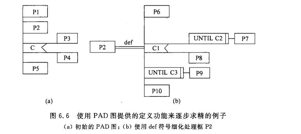
PAD The symbols of the diagram support top-down 、 The use of step-by-step refinement . At the beginning, the designer can define an abstract program , With the deepening of the design work and use def The symbols gradually add detail , Until the completion of the detailed design .
Example
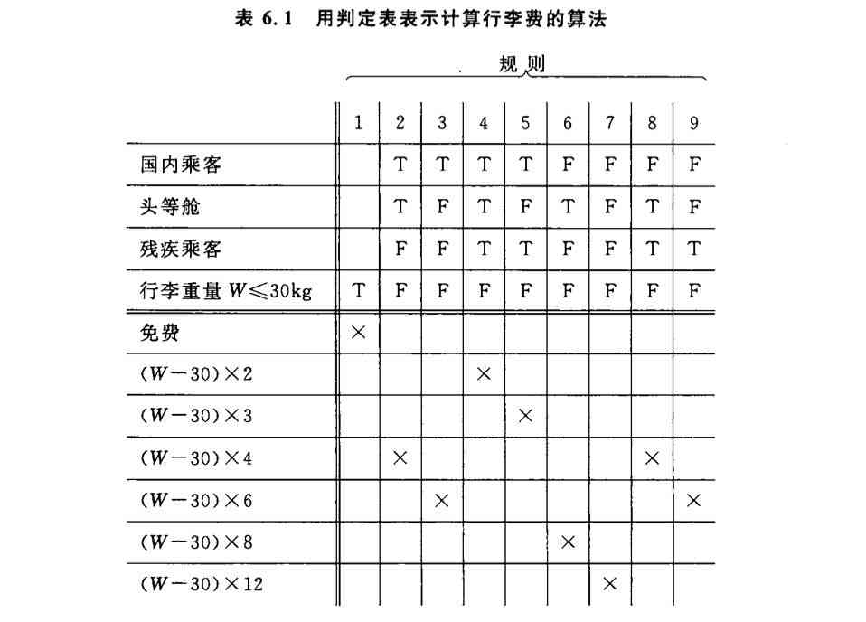
5.4 Decision table
The decision table can clearly show the corresponding relationship between the complex combination of conditions and the action to be done .
The decision table is made by 4 Part of it is made up of , The upper left section lists all the conditions , The lower left is all that can be done , The upper right is a matrix that represents the combination of various conditions , The lower right is the action corresponding to each combination of conditions . Each column in the right half of the decision table is essentially a rule , The action corresponding to a specific combination of conditions is specified .
Example
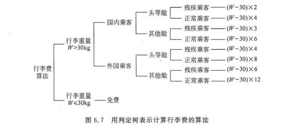
5.5 Decision tree
Although the judgment table can clearly show the corresponding relationship between the complex combination of conditions and the action to be done , But the meaning is not obvious at a glance .
Decision tree is a variety of decision table , It can also clearly show the corresponding relationship between the complex combination of conditions and the action to be done .
Example
6、 ... and 、 Postscript
This paper briefly describes some diagrams that are often used in software engineering , In fact, there are many pictures that are not introduced , such as UML( Standard drawing 、 Class diagram ) etc. , Interested partners can learn by themselves .
版权声明
本文为[Prosperity 3000]所创,转载请带上原文链接,感谢
边栏推荐
- Unexpected element.. required element
- Ora-02292: complete constraint violation (midbjdev2.sys_ C0020757) - subrecord found
- An article takes you to understand CSS pagination examples
- 2020-09-04: do you understand the function call convention?
- Can you do it with only six characters?
- All the way, I was forced to talk about C code debugging skills and remote debugging
- Windows 10 蓝牙管理页面'添加蓝牙或其他设备'选项点击无响应的解决方案
- How to prepare for the system design interview
- Visual rolling [contrast beauty]
- Introduction to Huawei cloud micro certification examination
猜你喜欢

jenkins安装部署过程简记
Introduction to the development of small game cloud
An article will take you to understand CSS alignment
Google browser realizes video playback acceleration function
Axios learning notes (2): easy to understand the use of XHR and how to package simple Axios
Event monitoring problem
The Interpreter pattern of behavior pattern
es创建新的索引库并拷贝旧的索引库 实践亲测有效!
Method of code refactoring -- Analysis of method refactoring
2020-09-04:函数调用约定了解么?
随机推荐
The essence of transaction and the principle of deadlock
2020-08-18:介绍下MR过程?
Exclusive interview of guests at | 2020 PostgreSQL Asia Conference: Wang Tao
es创建新的索引库并拷贝旧的索引库 实践亲测有效!
ES6 learning notes (3): teach you to use js object-oriented thinking to realize the function of adding, deleting, modifying and checking tab column
How to prepare for the system design interview
A concise tutorial for Nacos, ribbon and feign
Those who have worked in China for six years and a million annual salary want to share these four points with you
ES中删除索引的mapping字段时应该考虑的点
Ora-02292: complete constraint violation (midbjdev2.sys_ C0020757) - subrecord found
All the way, I was forced to talk about C code debugging skills and remote debugging
Road to simple HTML + JS to achieve the most simple game Tetris
Nodejs中使用jsonwebtoken(JWT)生成token的场景使用
Summary of front-end performance optimization that every front-end engineer should understand:
Basic usage of Vue codemirror: search function, code folding function, get editor value and verify in time
Zhou Jie: database system of East China Normal University
Erd-online free online database modeling tool
C calls SendMessage to refresh the taskbar icon (the icon does not disappear at the end of forcing)
上海巨微专用蓝牙广播芯片
Take you to learn the new methods in Es5