当前位置:网站首页>19.[STM32]HC_ SR04 ultrasonic ranging_ Timer mode (OLED display)
19.[STM32]HC_ SR04 ultrasonic ranging_ Timer mode (OLED display)
2022-07-05 15:48:00 【According to point_ DW】
Author's brief introduction : Hello, everyone , My name is DW, Share some of my new knowledge every day , Look forward to making progress with you
Series column :STM32
Small experimental target : stay OLED Displayed on the HC_SR04 Ranging value
If there is anything that is not well written, you are welcome to correctDevelopment board :STM32F103ret6
Creation time :2022 year 6 month 11 Japan
Catalog
Physical diagram connection diagram
HCSR_04 characteristic
HC_SR04 Ultrasonic ranging module can provide 2cm~400cm Non contact distance sensing function of , The ranging accuracy can reach 3mm; The module includes an ultrasonic transmitter 、 Receiver and control circuit .
Ultrasonic ranging principle
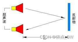
The principle of ultrasonic distance measurement is to send out ultrasonic waves in the ultrasonic transmitting device , Its basis is The time difference when the receiver receives the ultrasonic wave , Similar to the principle of radar ranging . An ultrasonic transmitter emits ultrasonic waves in a certain direction , The launch Start timing at the same time , Ultrasonic waves travel through the air , Come back immediately when you come across obstacles , When the ultrasonic receiver receives the reflected wave, it immediately stops timing .
Ultrasonic waves in the air Speed of propagation by 340m/s, according to timer Recorded time t( second ), You can calculate the distance between the starting point and the obstacle (s), namely :s=340t/2.
Physical diagram connection diagram

VCC for 5V Power Supply
GND Ground wire
Trig touch Hair control system Letter Number Input , And STM32 MCU connection PA6 Connect
Echo() Echo signal , And STM32 MCU connection PA7 Connect
HC_SR04 Programming
To configure IO mouth
initialization Trig and Echo Two pins , And configure timer interrupt .
u32 msCount = 0;

void HC_SR04_UserConfig(void){

	GPIO_InitTypeDef GPIO_InitStructure;
	TIM_TimeBaseInitTypeDef TIM_InitStructure;
	NVIC_InitTypeDef NVIC_InitStructure;


	RCC_APB2PeriphClockCmd(RCC_APB2Periph_GPIOA, ENABLE);	// Can make USART1,GPIOA The clock
	RCC_APB1PeriphClockCmd(RCC_APB1Periph_TIM6,ENABLE);		// Enable timer 6 The clock


	GPIO_InitStructure.GPIO_Pin = Trig; // Trigger the ranging pin
	GPIO_InitStructure.GPIO_Speed = GPIO_Speed_50MHz;
	GPIO_InitStructure.GPIO_Mode = GPIO_Mode_Out_PP;	// Push pull output
	GPIO_Init(HC_PROT, &GPIO_InitStructure);

	GPIO_InitStructure.GPIO_Pin = Echo; // Signal echo pin
	GPIO_InitStructure.GPIO_Mode = GPIO_Mode_IPD;	// The drop-down
	GPIO_Init(HC_PROT, &GPIO_InitStructure);

	TIM_DeInit(TIM6);
	TIM_InitStructure.TIM_Period = 1000-1;//1MS
	TIM_InitStructure.TIM_Prescaler = 72-1;// Pre distribution coefficient
	TIM_InitStructure.TIM_ClockDivision = TIM_CKD_DIV1;// Regardless of the frequency
	TIM_InitStructure.TIM_CounterMode = TIM_CounterMode_Up;// Count up
	TIM_InitStructure.TIM_RepetitionCounter = DISABLE;// Do not turn on repeat counting
	TIM_TimeBaseInit(TIM6,&TIM_InitStructure);// Timer initialization

	TIM_ClearFlag(TIM6,TIM_FLAG_Update);
	TIM_ITConfig(TIM6,TIM_IT_Update|TIM_IT_Trigger,ENABLE);// Enable interrupt source and interrupt trigger
	TIM_Cmd(TIM6,DISABLE);// off timer

	NVIC_PriorityGroupConfig(NVIC_PriorityGroup_0);
	NVIC_InitStructure.NVIC_IRQChannel = TIM6_IRQn;// choice TIM6 interrupt
	NVIC_InitStructure.NVIC_IRQChannelPreemptionPriority = 1;// preemption
	NVIC_InitStructure.NVIC_IRQChannelSubPriority = 0;// Child priority
	NVIC_InitStructure.NVIC_IRQChannelCmd = ENABLE;// Interrupt enable
	NVIC_Init(&NVIC_InitStructure);// Initialization interrupt


}
void TIM6_IRQHandler(void){

	if(TIM_GetITStatus(TIM6,TIM_IT_Update) != RESET){// Judge whether the interrupt is generated   1MS

		TIM_ClearITPendingBit(TIM6,TIM_IT_Update);// Clear the interrupt flag bit
		msCount++;
	}
}
Why configure Echo Pin for Drop down mode Well ? Because it can be seen from the sequence diagram , When no echo signal is detected ,Echo Always at low level , If the mode is set to floating, it is unstable .
When a signal is detected, the pin is pulled high , When no signal is detected, the pin Automatic lowering , So it is configured as a drop-down mode .

The above sequence diagram shows that you only need Provide a 10uS The above pulse trigger signal , The module Internal will send 8 individual 40kHz Cycle level and detect echo . once If an echo signal is detected, the echo signal is output . The pulse width of the echo signal is proportional to the distance measured . Thus, the interval between the time when the signal is transmitted and the time when the echo signal is received , You can calculate the distance .
The formula :uS/58= centimeter perhaps uS/148= Inch ; or : distance = High level time * The speed of sound (340M/S)/2; The recommended measurement period is 60ms above , To prevent the influence of the transmitted signal on the echo signal .
Ultrasonic ranging function
1. data1 For adoption Centimeter conversion Value ,data2 For adoption Sound velocity conversion Value .
2. We can know from the ultrasonic sequence diagram , When there is 10us When the trigger pulse above ,Echo In signal echo state , At the beginning, we are not sure that the echo signal is output at this time Echo Whether it is in the low-level state , So we must first judge Echo The level state of the pin , This is used to check whether the data conversion was completed last time , Then trigger the signal Trig.
	while(GPIO_ReadInputDataBit(HC_PROT,Echo) == 1);//!1, Then go to the next step

	Trig_High;
	delay_us(20);
Trig_Low;3. If there is a trigger signal Trig, The module will automatically generate 8 individual 40kHz Period level , Then judge Echo Whether there is high-level output ;
	while(GPIO_ReadInputDataBit(HC_PROT,Echo) == 0);//!=0
	TIM_SetCounter(TIM6,0);// Clear the counter
	msCount = 0;// Clear the interrupt counter value
TIM_Cmd(TIM6,ENABLE);// Turn on TIM6 interrupt 4. When Echo Not for high electricity , Then we record the next reverberation level , We close at this time TIM6.
	while(GPIO_ReadInputDataBit(HC_PROT,Echo) == 1);//!1
TIM_Cmd(TIM6,DISABLE);5. Get high level time , And carry out distance conversion .
	Count = msCount*1000;//us = ms * 1000
	Count = Count + TIM_GetCounter(TIM6);// High level time

	*data1 = Count/58;// us/58
	*data2 = Count*0.017;// 340 00/1000 000=0.034  0.034/2=0.017
    // There are two distances back and forth , So we need /2
	delay_ms(100);
The complete function code is as follows :
void HC_SR04_Ranging(u16 *data1,u16 *data2){

	u32 Count = 0;

	while(GPIO_ReadInputDataBit(HC_PROT,Echo) == 1);//!1, Then go to the next step

	Trig_High;
	delay_us(20);
	Trig_Low;

	while(GPIO_ReadInputDataBit(HC_PROT,Echo) == 0);//!=0
	TIM_SetCounter(TIM6,0);// Clear the counter
	msCount = 0;// Clear the interrupt counter value
	TIM_Cmd(TIM6,ENABLE);// Turn on TIM6 interrupt

	while(GPIO_ReadInputDataBit(HC_PROT,Echo) == 1);//!1
	TIM_Cmd(TIM6,DISABLE);// off timer

	Count = msCount*1000;//us = ms * 1000
	Count = Count + TIM_GetCounter(TIM6);// High level time

	*data1 = Count/58;// us/58
	*data2 = Count*0.017;// 340 00/1000 000=0.034  0.034/2=0.017
	delay_ms(100);
}
340m/s be equal to ? cm/us
1s=1000 000 us
340 00/1000 000=0.034
340m/s=0.034cm/us
6. In order to make the obtained data more accurate , We need multiple measurements to get the average .
void HC_SR04_Debolan(u8 mode){

	u16 data1 = 0,data2 = 0; u32 data = 0;
	HC_SR04_Ranging(&data1,&data2);

	if(mode){  // Centimeter conversion

		for(u8 i=0;i<5;i++){

			data = data + data1;
		}
		OLED_Write_Number(0,40,data/5);
	}
	else{	// Sound velocity conversion

		for(u8 i=0;i<5;i++){

			data = data + data2;
		}
		OLED_Write_Number(4,40,data/5);
	}
}
We configured two modes , Pattern 1 The value converted to centimeters , Pattern 0 Is the converted value of sound velocity .
7. The main function
#include "sys.h"
#include "delay.h"
#include "usart.h"
#include "oled.h"
#include "HC_SR04.h"


 int main(void)
 {
	  delay_init();
	  OLED_UserConfig();
	  OLED_Init();
	  OLED_Display_On();
	  HC_SR04_UserConfig();

	  //OLED_Display_Off();
 	while(1){

		    //OLED_Write_Number(2,40,131);
			HC_SR04_Debolan(1);// Centimeter conversion
	}
 }
All the source code has been introduced , We are in the ranging module 3cm Put obstacles out , You can see the number displayed on the LCD screen 3, In mode 1 And pattern 0 Can accurately measure the distance under .

In order to facilitate the next search , Remember to pay a little attention .
This chapter ends , I'll see you in the next chapter
Reference material :
1.STM32 Firmware library manual
2. The punctual atoms STM32 Incomplete manual _ Library function version
Data uploaded , You need to take it yourself
边栏推荐
- 六种常用事务解决方案,你方唱罢,我登场(没有最好只有更好)
- vlunhub- BoredHackerBlog Social Network
- Anti shake and throttling
- I spring web upload
- Common PHP interview questions (1) (written PHP interview questions)
- Lesson 4 knowledge summary
- 17.[STM32]仅用三根线带你驱动LCD1602液晶
- Hongmeng system -- Analysis from the perspective of business
- 我们为什么要学习数学建模?
- 【简记】解决IDE golang 代码飘红报错
猜你喜欢
OSI 七层模型
Analytic hierarchy process of mathematical modeling (including Matlab code)

wxml2canvas

"Sequelae" of the withdrawal of community group purchase from the city
![P1451 calculate the number of cells / 1329: [example 8.2] cells](/img/c4/c62f3464608dbd6cf776c2cd7f07f3.png)
P1451 calculate the number of cells / 1329: [example 8.2] cells
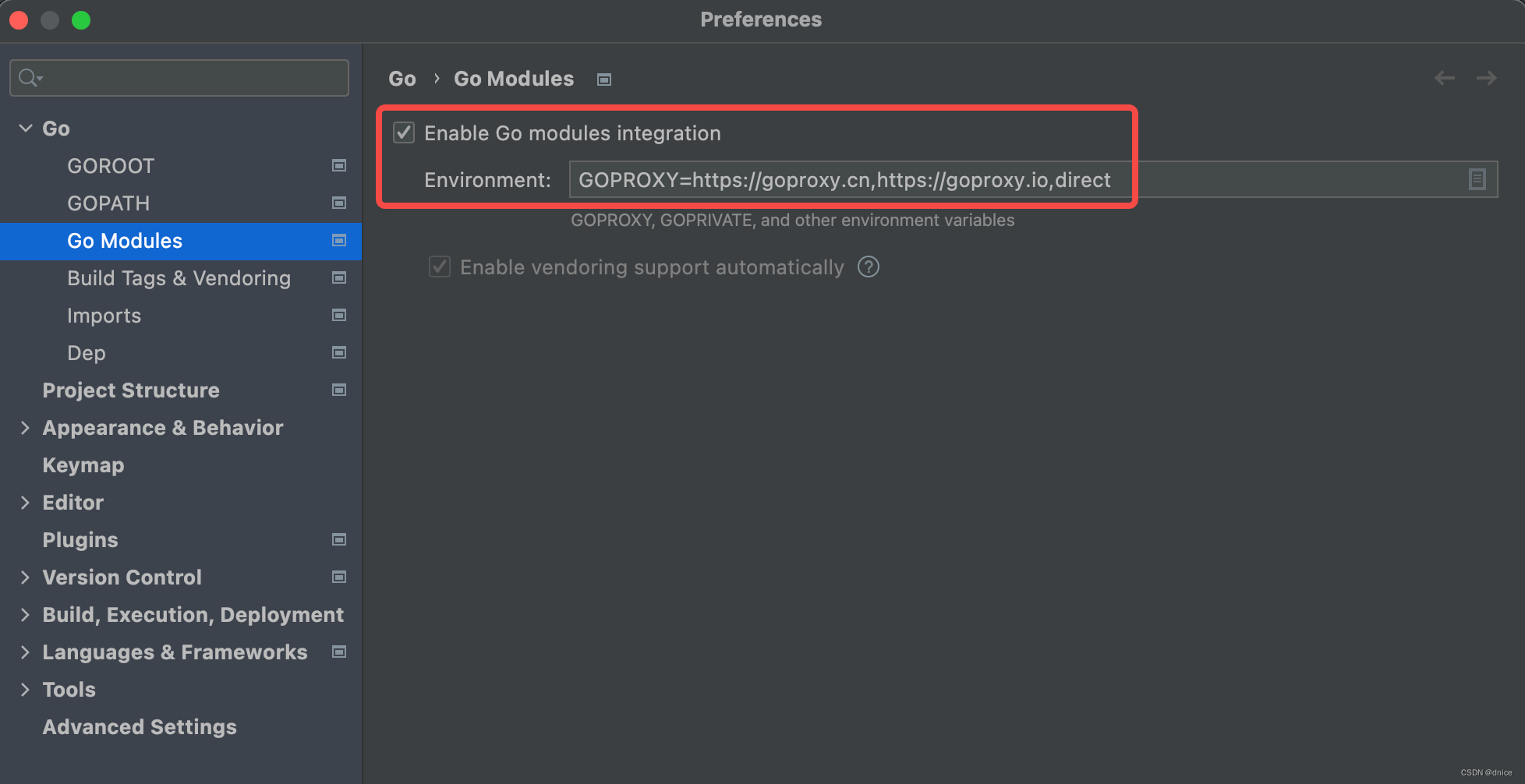
【 note 】 résoudre l'erreur de code IDE golang
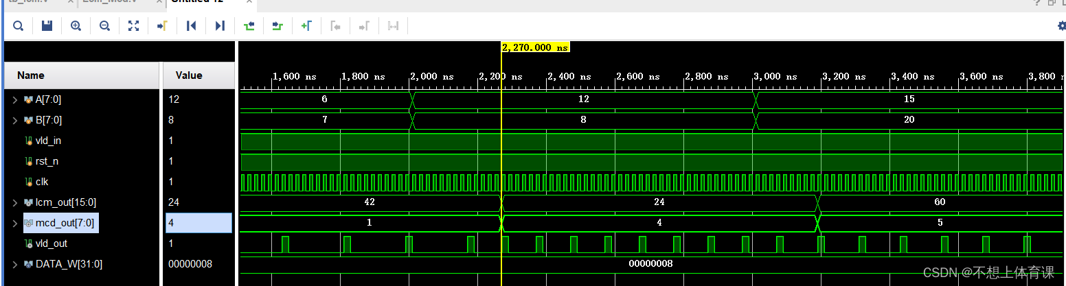
verilog实现计算最大公约数和最小公倍数
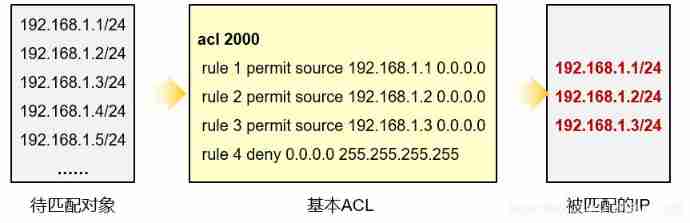
Data communication foundation ACL access control list
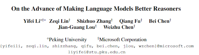
Surpass palm! Peking University Master proposed diverse to comprehensively refresh the NLP reasoning ranking

CODING DevSecOps 助力金融企业跑出数字加速度
随机推荐
示例项目:简单的六足步行者
First PR notes
Arduino控制微小的六足3D打印机器人
Verilog realizes the calculation of the maximum common divisor and the minimum common multiple
2.3 learning content
修改pyunit_time使得其支持‘xx~xx月’的时间文本
如何将 DevSecOps 引入企业?
Garbage collection mechanism of PHP (theoretical questions of PHP interview)
"Sequelae" of the withdrawal of community group purchase from the city
Clock switching with multiple relationship
mapper.xml文件中的注释
P6183 [USACO10MAR] The Rock Game S
OceanBase社区版之OBD方式部署方式本地安装
Information collection of penetration test
Common PHP interview questions (1) (written PHP interview questions)
超越PaLM!北大碩士提出DiVeRSe,全面刷新NLP推理排行榜
Bugku alert
Redis distributed lock principle and its implementation with PHP (1)
Talk about your understanding of microservices (PHP interview theory question)
记录一下树莓派搭建环境中遇到的坑。。。