当前位置:网站首页>[Digital IC manual tearing code] Verilog asynchronous reset synchronous release | topic | principle | design | simulation
[Digital IC manual tearing code] Verilog asynchronous reset synchronous release | topic | principle | design | simulation
2022-07-06 02:29:00 【myhhhhhhhh】
Preface
This series aims to provide 100% Accurate numbers IC Design / Verify the title of the hand tearing code link , principle ,RTL Design ,Testbench And reference simulation waveform , The content of each article is checked by simulation . The quick navigation links are as follows :
Odd frequency division
Even frequency division
Semi integer batch
decimal / Fractional frequency division
Sequence detector
Mode three detector
Beverage machine
Asynchronous reset , Simultaneous release
Edge detection ( Rising edge , Falling edge , On both sides )
Full adder , Half adder
Gray code to binary
single bit Cross clock domain ( Two beats , Edge synchronization , Pulse synchronization )
Sync FIFO
Ought to say , The hand tearing code link is in the interview process Both important and simple A part of , Compared with software jobs , Numbers IC Hand tear code Fixed topic , Limited number , It belongs to a link that must be scored in the whole interview , Outside this series , I also recommend numbers IC Job seekers use “HdlBits” Code Training
Links are as follows
HDLBits — Verilog Practice
Asynchronous reset synchronous release problem
Use Verilog Code , Complete the design of asynchronous reset and synchronous release circuit
The principle of asynchronous reset and synchronous release
One with asynchronous reset end DFF workflow
If one DFF The reset value of is 0, that rst_n=0 When the signal comes , The DFF Reset , When rst_n=1 When the signal comes , The DFF Normal work .
Possible problems
When rst_n The signal returns 1 Time and clk When the signal coming from the rising edge is very close ,DFF Metastable state may be output , The reason why the signal cannot be recognized is 1 still 0
terms of settlement
Asynchronous reset : Yes 0 The reset signal of is not processed , Let it reset normally asynchronously
Simultaneous release : Yes 1 Make two beats of the reset signal , Align the edge of the clock when it is pulled up , In order to avoid metastable state
Sequence diagram of asynchronous reset and synchronous release 
RTL Design
module rst_asy(clk,rst_n,rst_out);

input clk;
input rst_n;
output reg rst_out;

reg rst_r1;

[email protected](posedge clk or negedge rst_n)
if(!rst_n)
begin
rst_out<= 1'b0;
rst_r1 <= 1'b0;
end
else
begin
rst_r1 <= rst_n;
rst_out <= rst_r1;
end

endmodule
Testbench Code
`timescale 1ns /1ps
module rst_asy_tb();
reg clk ;
reg rst_n;
wire rst_out;

rst_asy u1(.clk(clk),.rst_n(rst_n),.rst_out(rst_out));

always #5 clk = !clk;

initial
begin
clk = 0;
rst_n = 1;
#7
rst_n = 0;
#5
rst_n = 1;
#30
$stop;
end

endmodule
Simulation analysis

rst_n After re raising ,rst_out Wait for the register to save twice before output , Metastable state is avoided , Design establishment
边栏推荐
- [postgraduate entrance examination English] prepare for 2023, learn list5 words
- Thinking on Architecture Design (under continuous updating)
- A doctor's 22 years in Huawei
- 我把驱动换成了5.1.35,但是还是一样的错误,我现在是能连成功,但是我每做一次sql操作都会报这个
- 2020.02.11
- RDD partition rules of spark
- 模板_快速排序_双指针
- 大厂镜像库
- Reset nodejs of the system
- Minecraft 1.16.5 生化8 模组 2.0版本 故事书+更多枪械
猜你喜欢

3D drawing ()

The ECU of 21 Audi q5l 45tfsi brushes is upgraded to master special adjustment, and the horsepower is safely and stably increased to 305 horsepower
Using SA token to solve websocket handshake authentication
Reset nodejs of the system
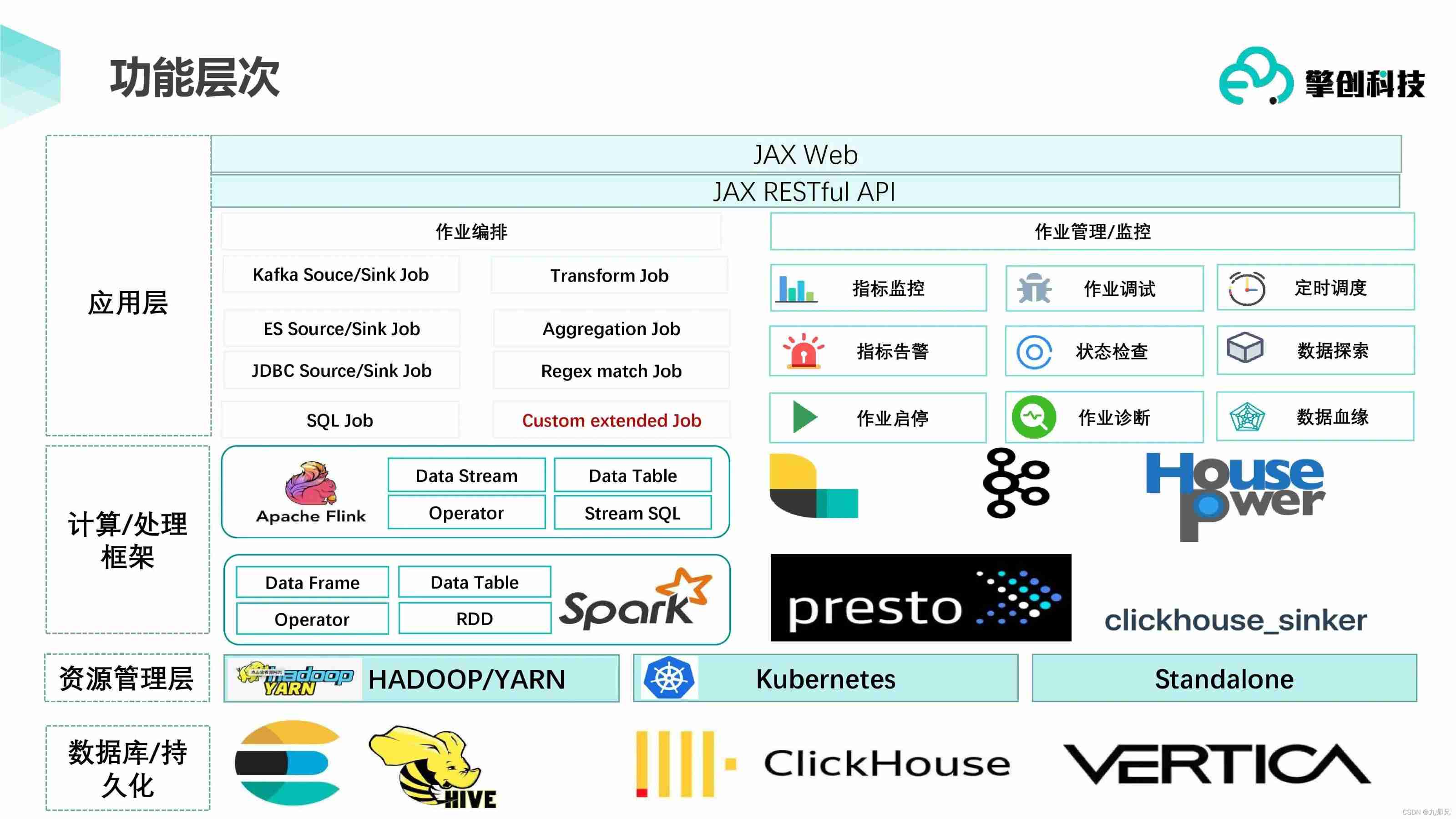
【clickhouse】ClickHouse Practice in EOI
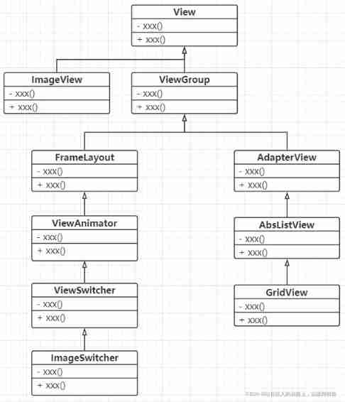
Use image components to slide through photo albums and mobile phone photo album pages

2022.02.13
【无标题】数据库中一条查询SQL执行的过程
技术管理进阶——什么是管理者之体力、脑力、心力
Minecraft 1.18.1、1.18.2模组开发 22.狙击枪(Sniper Rifle)
随机推荐
Shell脚本更新存储过程到数据库
Multi function event recorder of the 5th National Games of the Blue Bridge Cup
Xshell 7 Student Edition
【机器人库】 awesome-robotics-libraries
MySQL lethal serial question 1 -- are you familiar with MySQL transactions?
Global and Chinese markets for single beam side scan sonar 2022-2028: Research Report on technology, participants, trends, market size and share
Black high-end responsive website dream weaving template (adaptive mobile terminal)
Prepare for the autumn face-to-face test questions
【coppeliasim】高效传送带
Multiple solutions to one problem, asp Net core application startup initialization n schemes [Part 1]
【社区人物志】专访马龙伟:轮子不好用,那就自己造!
Know MySQL database
数据准备工作
[robot library] awesome robots Libraries
How to generate rich text online
Using SA token to solve websocket handshake authentication
General process of machine learning training and parameter optimization (discussion)
MySQL learning notes - subquery exercise
剑指 Offer 29. 顺时针打印矩阵
Method of changing object properties