当前位置:网站首页>OS i/o devices and device controllers
OS i/o devices and device controllers
2022-07-06 00:08:00 【Alkali!】
I/O The equipment is generally executed by I/O The mechanical part of operation and execution control I/O The electronic components of . These two parts are usually separated , perform I/O The mechanical part of the operation is general I/O equipment , And executive control I/O The electronic components of the are called device controllers or adapters ( adapter ). In microcomputers and minicomputers, controllers are often made into printed circuit cards, so they are often called control cards 、 Interface card or network card , It can be inserted into the expansion slot of the computer . In some big 、 In medium-sized computer systems , Also configured I/O Channel or I/O processor .
I/O equipment
I/O Type of equipment
IO There are many types of equipment , In addition to being able to divide them into block devices and character devices 、 Exclusive devices and shared devices , It can also be divided into storage devices and I/O equipment ; From the transmission rate of equipment, it can be divided into high-speed equipment 、 Medium speed sharing devices and high-speed sharing devices . These two categories are introduced below .
1) Classified by service characteristics
The first category is The storage device , Also known as external storage 、 Auxiliary deposit , It is the main device used to store information . The access speed of this kind of device is slower than that of memory , But the capacity is much larger , It's also cheap . The second is I / O equipment , It can also be divided into input devices 、 Output devices and interactive devices . Input devices are used to receive external information , Like a keyboard 、 mouse 、 Scanner 、 Video camera, etc . The output device is used to send the information processed by the computer to the device outside the processor , Such as a printer 、 Plotters, etc . Interactive devices refer to the above two types of integrated devices , Mainly display , It is used to synchronously display user commands and the results of command execution .
2) By transmission rate
According to the transmission speed , Can be I/O The equipment is divided into three categories . The first category is Low speed equipment , Its transmission rate is only a few bytes to hundreds of bytes per second . A typical low-speed device has a keyboard 、 Mouse device . The second type is Medium speed equipment , Its transmission rate ranges from thousands of bytes to hundreds of thousands of bytes per second . Typical medium speed devices are line printers 、 Laser printers, etc . The third kind is High speed equipment , Its transmission rate ranges from hundreds of thousands of bytes to gigabytes . Typical high-speed devices are tape drives 、 Disk drive 、 CD player, etc .
Interface between equipment and controller
Usually , The device is not directly related to CPU communicate , Instead, it communicates with the device controller , therefore , stay I/O The equipment shall include the interface with the equipment controller , There are three types of signals in this interface ( See the picture 6-3 Shown ), Each corresponds to a signal line .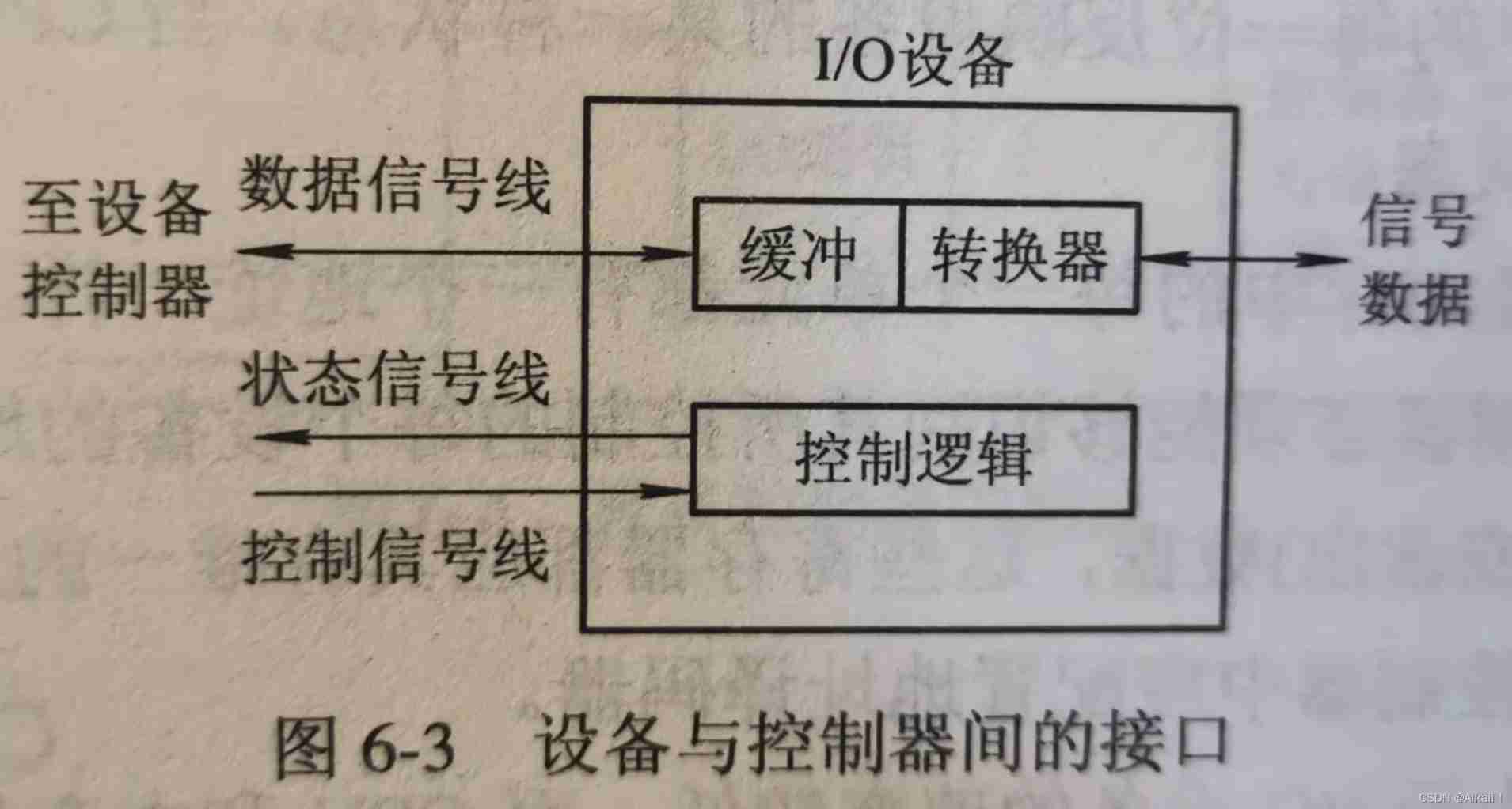
(1) Data signal line
This kind of signal line is used to transmit data signals between the device and the device controller . For input devices , The signal input from the outside is converted by the converter , The formed data is usually sent to the buffer first , When the amount of data reaches a certain bit ( character ) After counting , Then it is transmitted from the buffer to the device controller through a group of data signal lines , Pictured 6-3 Shown . For output devices , A batch of data transmitted from the device controller through the data signal line is temporarily stored in the dry buffer , After proper conversion by the converter , Then output character by character .
(2) Control signal line
This is done by the device controller to I / O The path through which the device sends control signals . This signal specifies the operation to be performed by the equipment , Such as reading operation ( It refers to the transmission of data from the equipment to the controller ) Or write operations ( Receive data from the controller ), Or perform operations such as head movement .
(3) Status signal line
The signal line is used to transmit a signal indicating the current state of the device . The current state of the device is reading ( Or write ); Device read ( Write ) complete , And prepare for new data transmission .
Device controller
The main functions of the device controller are , Control one or more I / O equipment , In order to realize the I / O Data exchange between devices and computers . It is CPU And I / O Interfaces between devices , Receive from CPU Orders sent , To control the I / O The equipment works , Enable the processor to free itself from complicated equipment control transactions . The device controller is an addressable device , When it controls only one device , It only has a unique device address ; If the controller can be connected to multiple devices , It should contain multiple device addresses , Each device address corresponds to a device . Device controllers can be divided into two categories : One is the controller used to control character devices , The other is a controller for controlling block devices .
1. Basic functions of equipment controller
(1) Receive and recognize commands
The device controller can receive and recognize various commands sent by the processor . There are corresponding control registers in the controller , Used to store received commands and parameters , And decode the received command . for example , The disk controller can receive CPU It's from read 、 write 、 format etc. 15 Different commands , And some commands also have parameters . Accordingly , There are multiple registers and command decoders in the disk controller .
(2) Data exchange
The device controller can realize CPU And the controller 、 Between controller and equipment Data exchange of . For the former , Through the data bus , from CPU Write data to the controller in parallel , Or read data from the controller in parallel . For the latter , It is the device that inputs data to the controller , Or from the controller to the device . So , The data register must be set in the controller .
(3) Identify and report the status of the equipment
The controller shall record the status of the equipment for CPU understand . for example , Only when the device is in send ready state , CPU To start the controller to read data from the device . So , Set a status register in the controller , Use each of them to reflect a certain state of the equipment . When CPU After reading the contents of this register , You can know the status of the equipment .
(4) Address recognition
Just like every cell in memory has an address , Every device in the system also has an address . The device controller must be able to identify the address of each device it controls . Besides , To make CPU Be able to turn to ( Or from ) Write in the register ( Or read out ) data , These registers should have unique addresses . The controller shall be able to correctly identify these addresses . So , The address decoder should be configured in the controller .
(5) Data buffer
because I / O The speed of the device is low , and CPU And memory speed is very high , Therefore, a buffer must be set in the controller . At output time , Use this buffer to temporarily store the data transmitted by the host at a high speed , Then with I / O The device transmits the data in the buffer to at a rate matched by the device I / O equipment . On input , The buffer is used for temporary storage from I / O Data sent by the equipment , After receiving a batch of data , Then the data in the buffer is transmitted to the host at a high speed .
(6) Error control
For the I / O Data transmitted by the device , The device controller is also responsible for error detection . If an error is found in the transmission , Usually, the error detection code is set , And to CPU The report , therefore CPU Invalidate the data transmitted this time , And re transmit . This will ensure the correctness of data input .
The composition of the device controller
Because the device controller is located in CPU Between and equipment , It should be related to CPU signal communication , And communicate with the device , It shall also have the following functions: CPU The command sent to control the function of the equipment , therefore , Most of the existing controllers are composed of the following three parts :
(1) Interface between equipment controller and processor
This interface is used to implement CPU Communication with the device controller , There are three types of signal lines in this interface : cable 、 Address lines and control lines .
Data lines are usually connected to two types of registers :
- ① The first category is Data register , There can be one or more data registers in the controller , It is used to store the data sent from the equipment ( Input ), Or from CPU The data that came in ( Output ).
- ② The second type is control / Status register , There can be one or more of these registers in the controller , Used to store from CPU Control information or equipment status information sent .
(2) The interface between the device controller and the device
On a device controller , One or more devices can be connected . Corresponding , There are one or more device interfaces in the controller . There is data in every interface 、 Three types of signals, control and status . In the controller I / O The logic selects a device port according to the address signal sent by the processor .
(3) I / O Logic
I / O Logic is used to control the equipment . It interacts with the processor through a set of control lines , The processor uses this logic to send a message to the controller I / O command . whenever CPU To start a device , On the one hand, send the start command to the controller , On the other hand, it sends the address to the controller through the address line , By the controller I / O Logic decodes the received address , Then control the selected equipment according to the translated command .
The composition of the device controller is shown in Figure 6-4 in .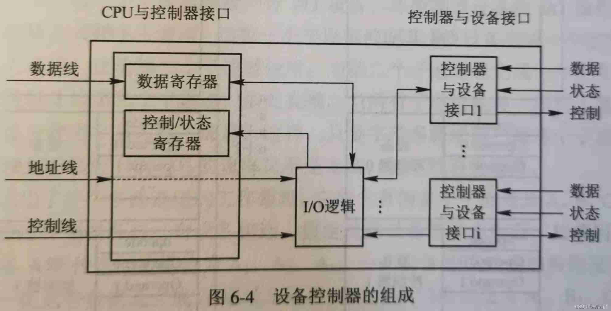
Memory image I / O
The driver will be abstract I / O A series of specific commands converted from commands 、 Parameters and other data are loaded into the corresponding registers of the device controller , The controller executes these commands , The specific implementation is right I / O Control of equipment . This work can be done in the following two ways :
1. Use specific I / O Instructions
In early computers , Including mainframe computers , In order to achieve CPU Communication with device controller , Assign one to each control register I / O port , This is a 8 Bit or 16 An integer , Pictured 6-5( a ) Shown . In addition, some specific I / O Instructions . for example , In order to CPU The contents of the register are copied into the controller register , Specific to be used I/O Instructions can be expressed as follows :
io-store cpu-reg,dev-no,dev-reg
among , cpu-reg yes CPU Some register of ;dev-no Is the designated device , Controller address ; dev-reg Specify the registers in the controller .
If it's going to be CPU The contents of the register are stored in a unit of memory (k) in , The following instructions will be used :
Store cpu-reg,k
The main disadvantage of this method is , Access to memory and access to devices require two different instructions .
2. Memory image I / O
In this way , In addressing, the memory unit address and the register address in the device controller are no longer distinguished , All use k . When k Value in 0~ n -1 Range time , Considered a memory address , if k Greater than or equal to n when , It is considered to be the register address of a controller . From the figure 6-5( b ) It can be seen that , When k = n when , Indicates the device controller 0 Of the 1 A register opcode The address of . therefore , If you want to CPU The contents of the register are transferred to the controller 0 Of the 1 A register opcode , Just use the following general storage instructions :
Store cpu-reg,n
Memory image I / O Method unifies the access methods to memory and controller , This will undoubtedly simplify I / O Programming for .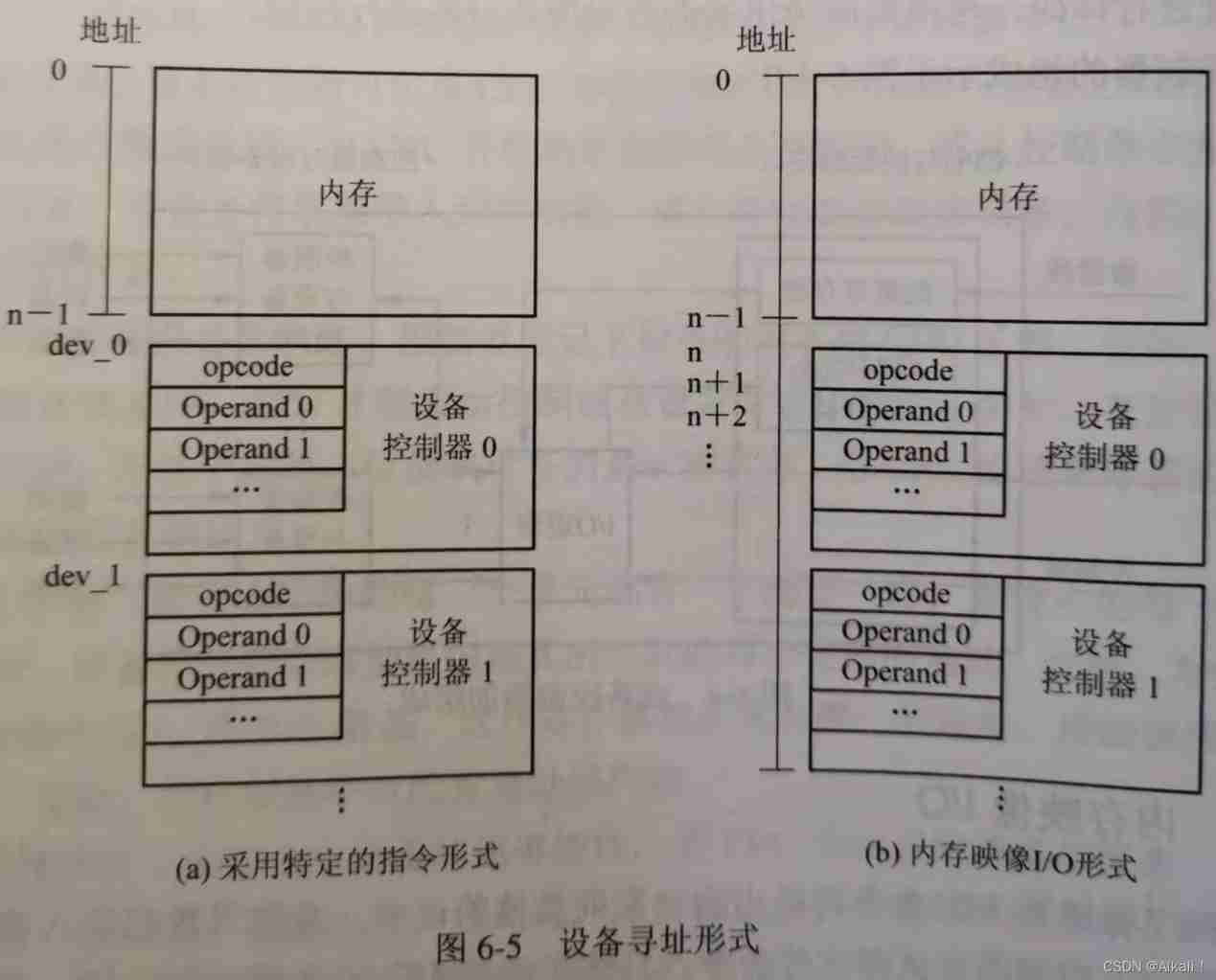
I / O passageway
1. l / O Introduction of channel equipment
Although in CPU And I / O After adding a device controller between devices , Can greatly reduce CPU Yes I / O Intervention , But when the host is configured with many peripherals , CPU The burden is still heavy . So , stay CPU And equipment controller I / O passageway ( I / O Channel ). Its main purpose is to establish an independent I / O operation , Not only can the transmission of data be independent of CPU , And also hope that the relevant to I / O Organization of operations 、 Manage and end processing as independently as possible , In order to make sure CPU More time for data processing ; Or say , Its purpose is to make some original CPU To deal with the I / O The task is transferred to the channel , So that CPU From complicated I / O Free yourself from the task . After setting the channel , CPU Just send one... To the channel I / O Instructions . After receiving the command, the channel , Then take out the channel program to be executed this time from the memory , Then execute the channel program , Only when the channel has completed the specified I / O After the task , Just to CPU Send an interrupt signal .
actually , I/O A channel is a special processor . It has the ability to execute I / O The ability to command , And control by executing the channel program I / O operation . but I / O The channel is different from the general processor , Mainly in the following two aspects : One is Its instruction type is single , This is because the channel hardware is relatively simple , The command it can execute , Mainly limited to I/O Operation related instructions ; Two is Channels don't have their own memory , The channel program executed by the channel is placed in the memory of the host , In other words , It's channels and CPU Shared memory .
2. Channel type
As mentioned before , Channels are used to control peripheral devices ( Including character devices and block devices ) Of . Because there are many types of peripheral devices , And its transmission rate varies greatly , Thus, there are many types of channels . here , According to the different ways of information exchange , Channels can be divided into the following three types .
1) Byte multichannel ( Byte Multiplexor Channel )
This is a kind of Work in byte crossing The passage of . It usually contains many non distributive subchannels , The number can range from dozens to hundreds , Each subchannel is connected to one I / O equipment , And control the operation of the equipment I / O operation . These subchannels press Time slice rotation mode Share the main channel . When the first subchannel controls its I / O After the device completes the exchange of one byte , Immediately vacate the main channel , Let the second subchannel use ; When the second subchannel also completes the exchange of a byte , Also give up the main channel to the third sub channel ; And so on . When all subchannels rotate for a week , Return to the first subchannel to use byte multiplex main channel . such , As long as the byte multichannel scans each subchannel fast enough , The speed of devices connected to subchannels is not too high , Will not lose information .
chart 6-6 It shows the working principle of byte multichannel . It contains several sub channels A , B , C , D , E ,…, N …, They are respectively connected with one device through the controller . Assume that the speed of these devices is similar , And all transmit data to the host at the same time . equipment A The data stream transmitted is A1, A2, A3,…; equipment B The data stream transmitted is B1, B2, B3,…;…… After synthesizing these data streams ( Through the main channel ) The data flow sent to the host is A1, B1, C1, D1 ,… A2 , B2 , C2 , D2 ,…, A3 , B3 , C3 , D3 ,…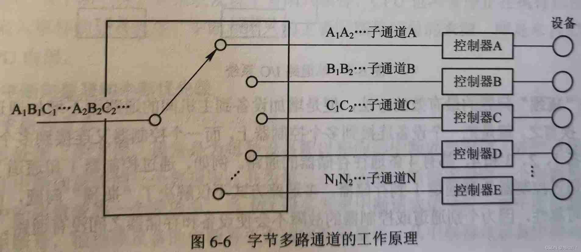
2) Array selection channel ( Block Selector Channel )
Byte multichannel is not suitable for connecting high-speed devices , This promotes the formation of array selection channels for data transmission in array mode . Although this channel can connect multiple high-speed devices , But because it only contains one distributive subchannel , Only one channel program can be executed in a period of time , Control a device for data transmission , As a result, when a device occupies the channel , It has been monopolized by it , Even if it has no data transmission , The channel is idle , Other devices are not allowed to use this channel , Until the transmission of the device is completed, release the channel . so , The utilization rate of this channel is very low .
3) Array multichannel ( Block Multiplexor Channel )
Although the array selection channel has a high transmission rate , But it allows only one device to transmit data at a time . Array multichannel is to select the channel of array. The high transmission rate and byte multichannel can make each subchannel ( equipment ) A new channel formed by the combination of the advantages of time-sharing parallel operation . It contains multiple unallocated subchannels , Therefore, this channel has high data transmission rate , It can also obtain satisfactory channel utilization . That's why , So that the channel can be widely used to connect multiple high 、 Medium speed peripherals , Its data transmission is carried out in the form of array .
3.“ bottleneck ” problem
Because the channel is expensive , As a result, the number of channels set in the machine is bound to be less , This often makes it I/O Bottleneck , Thus, the throughput of the whole system decreases . for example , In the figure 6-7 in , Suppose the device 1 To equipment 4 There are four disks , To boot the disk 4, You must use channels 1 And controller 2; But if these two have been occupied by other equipment , The disk must not start 4. Similarly , To start the disk 1 And plates 2, Because they all use channels 1, Therefore, it is impossible to start . These are caused by insufficient channels “ bottleneck ” The phenomenon .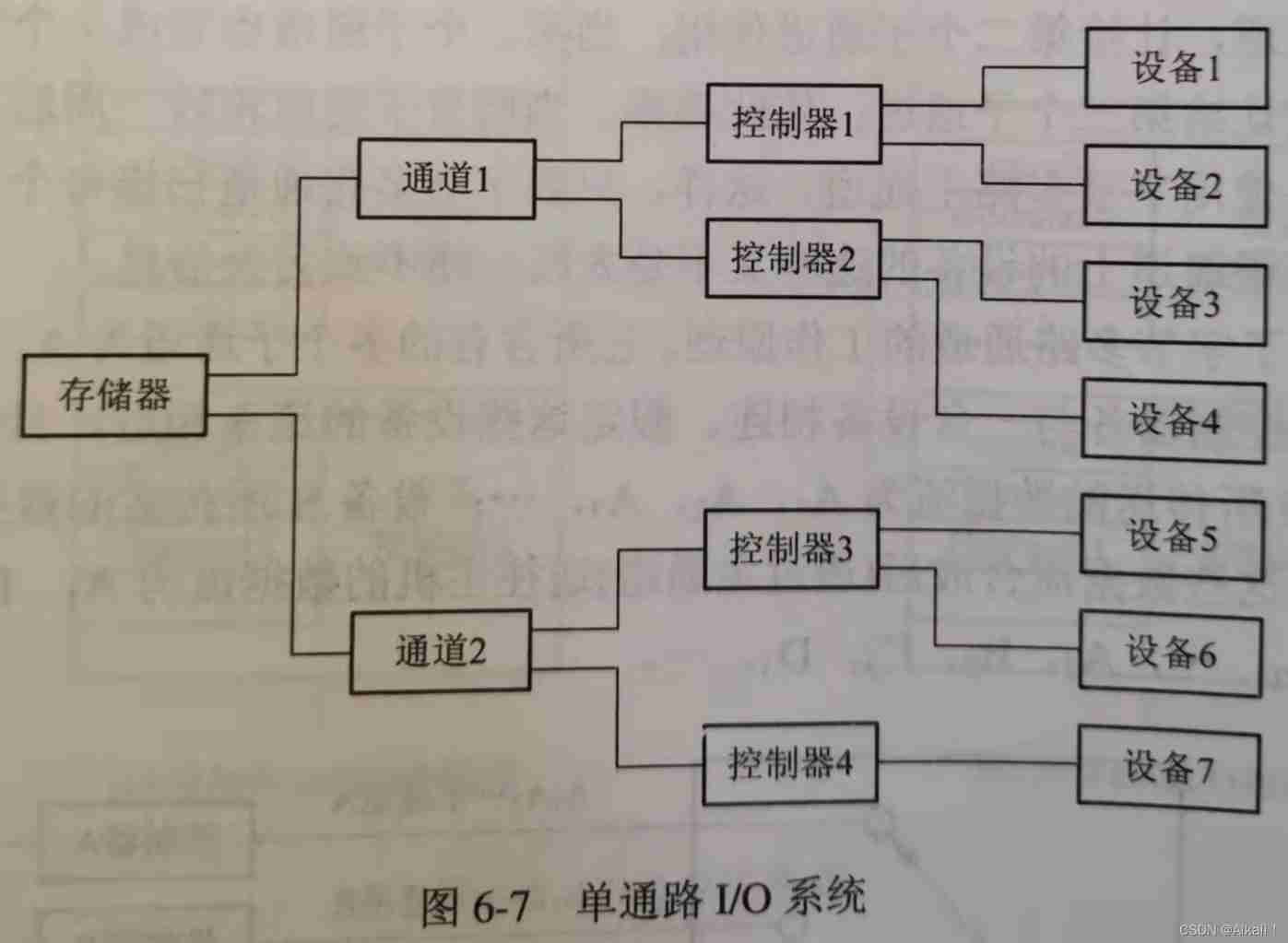
solve “ bottleneck ” The most effective way to solve the problem , That is Increase the channel from the equipment to the host without increasing the channel , Pictured 6-8 Shown . In other words , Namely Connect a device to multiple controllers , And one controller is connected to multiple channels . The equipment in the figure 1、2、3 and 4, There are 4 A path to memory . for example , Through the controller 1 And channel 1 To memory ; You can also use the controller 2 And channel 1 To memory . The multi-channel method not only solves “ bottleneck ” problem , And it improves the reliability of the system , Because the failure of individual channels or controllers will not make there is no path between the device and the memory .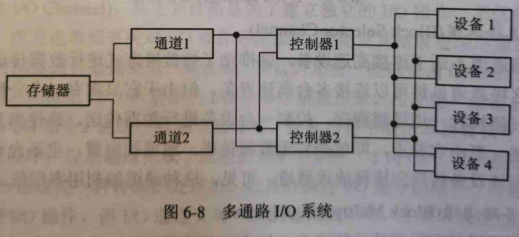
边栏推荐
- Huawei equipment configuration ospf-bgp linkage
- FFMPEG关键结构体——AVCodecContext
- The difference of time zone and the time library of go language
- 行列式学习笔记(一)
- 【NOI模拟赛】Anaid 的树(莫比乌斯反演,指数型生成函数,埃氏筛,虚树)
- MySql——CRUD
- How to get all the values stored in localstorage
- 【QT】Qt使用QJson生成json文件并保存
- Recognize the small experiment of extracting and displaying Mel spectrum (observe the difference between different y_axis and x_axis)
- Add noise randomly to open3d point cloud
猜你喜欢
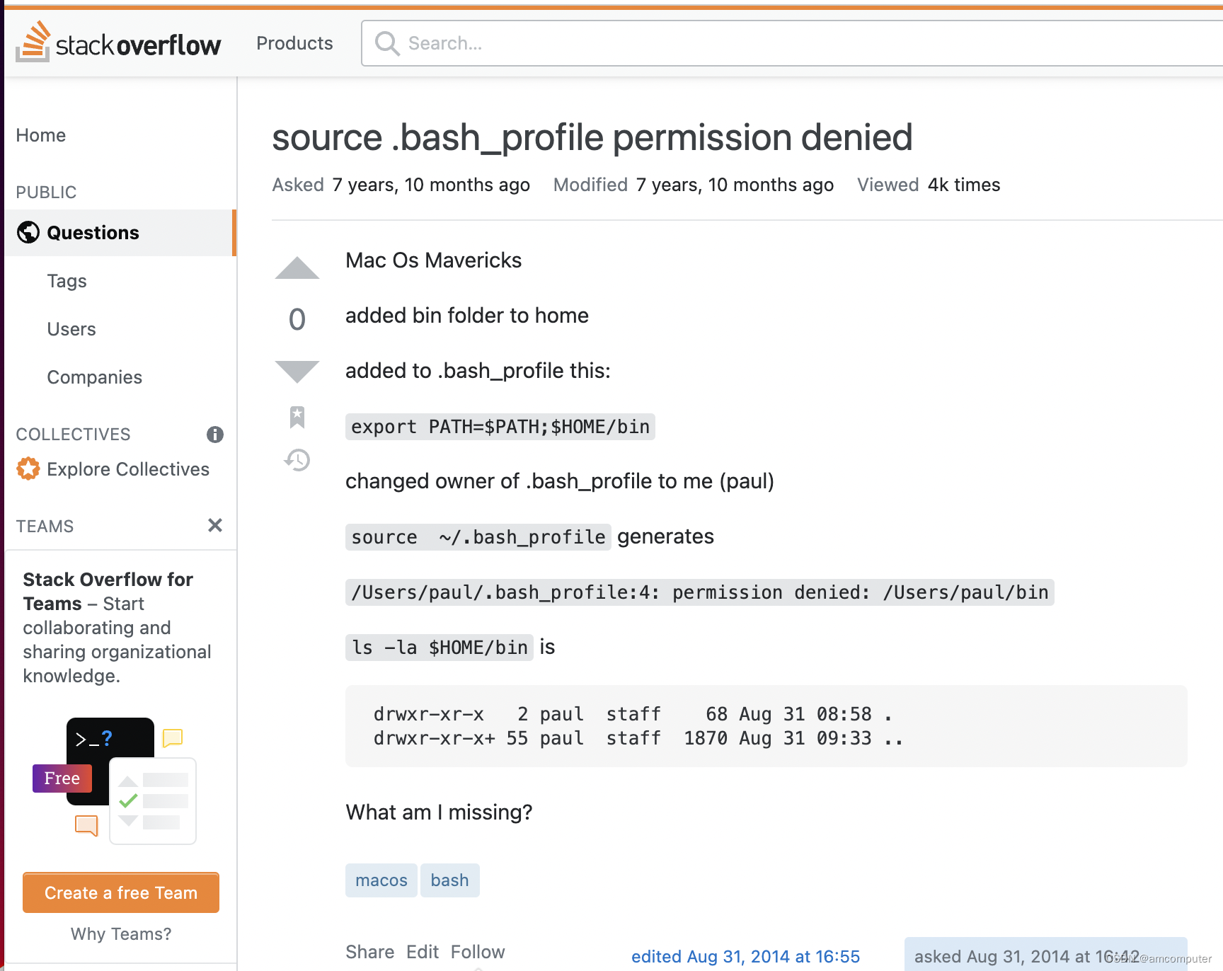
权限问题:source .bash_profile permission denied

妙才周刊 - 8
激光slam学习记录
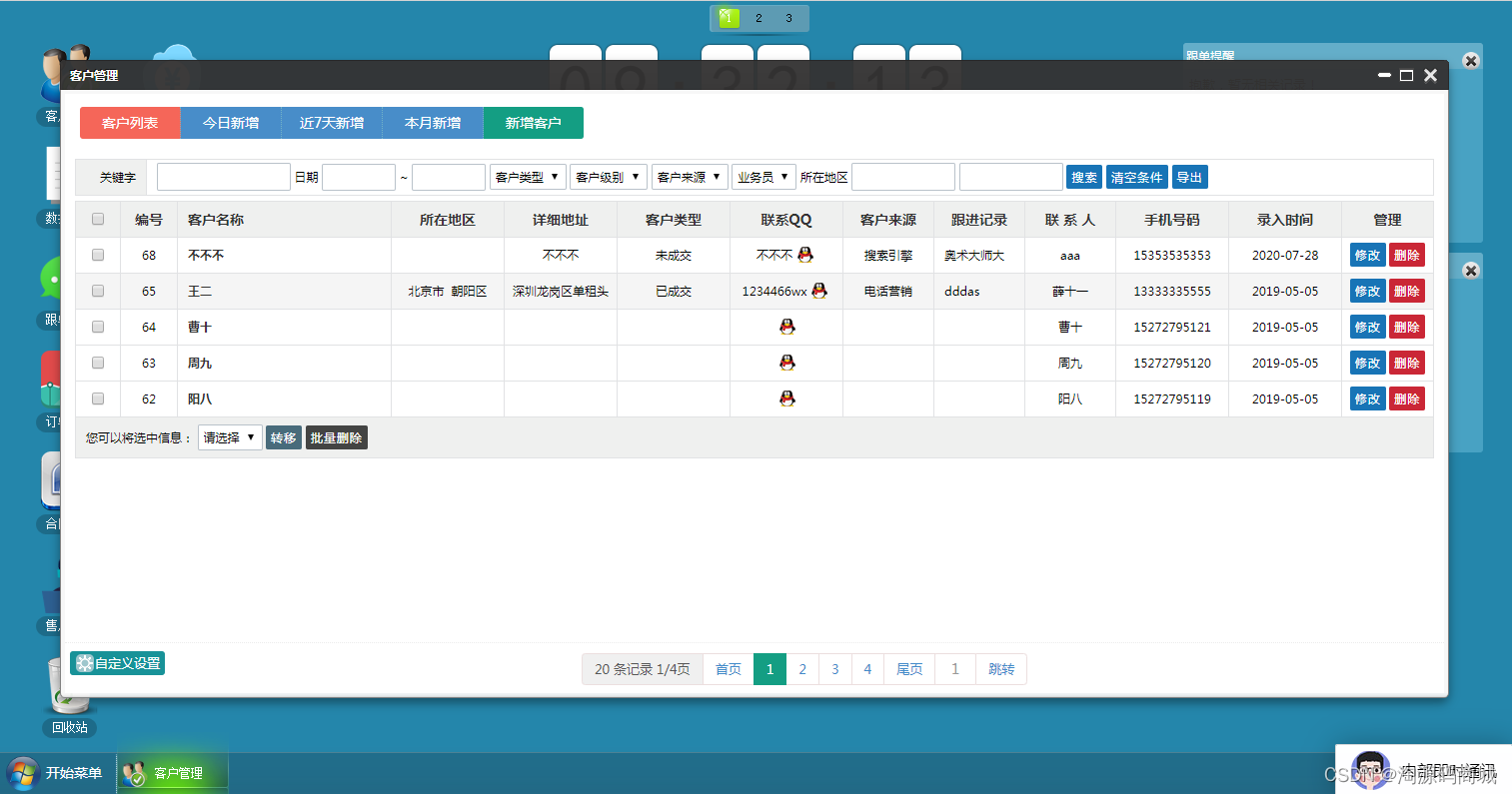
Open source CRM customer relationship system management system source code, free sharing
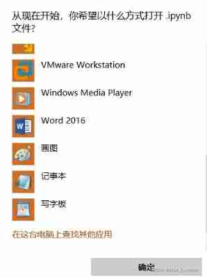
Problem solving win10 quickly open ipynb file
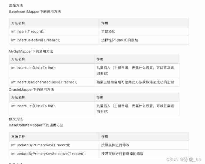
Use mapper: --- tkmapper
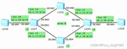
Configuring OSPF load sharing for Huawei devices
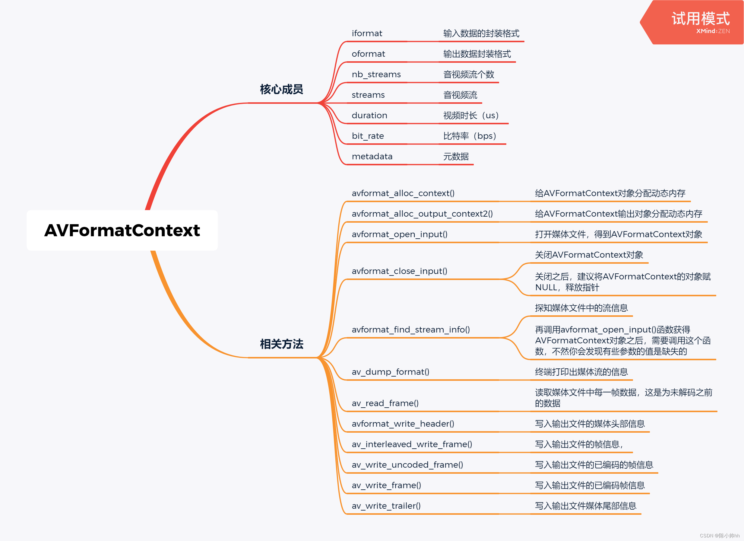
FFMPEG关键结构体——AVFormatContext
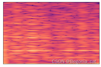
Recognize the small experiment of extracting and displaying Mel spectrum (observe the difference between different y_axis and x_axis)
Tools to improve work efficiency: the idea of SQL batch generation tools
随机推荐
Doppler effect (Doppler shift)
Knowledge about the memory size occupied by the structure
MySQL global lock and table lock
MySql——CRUD
wx. Getlocation (object object) application method, latest version
openssl-1.0.2k版本升级openssl-1.1.1p
【在线聊天】原来微信小程序也能回复Facebook主页消息!
时区的区别及go语言的time库
What are the functions of Yunna fixed assets management system?
剖面测量之提取剖面数据
wx.getLocation(Object object)申请方法,最新版
选择致敬持续奋斗背后的精神——对话威尔价值观【第四期】
教你在HbuilderX上使用模拟器运行uni-app,良心教学!!!
VBA fast switching sheet
什么叫做信息安全?包含哪些内容?与网络安全有什么区别?
USB Interface USB protocol
JS can really prohibit constant modification this time!
Key structure of ffmpeg -- AVCodecContext
MySql——CRUD
FFT 学习笔记(自认为详细)