当前位置:网站首页>Data communication foundation smart_ Link_&_ Monitor_ Link
Data communication foundation smart_ Link_&_ Monitor_ Link
2022-07-05 15:36:00 【GALi_ two hundred and thirty-three】
SmartLink
Technical background
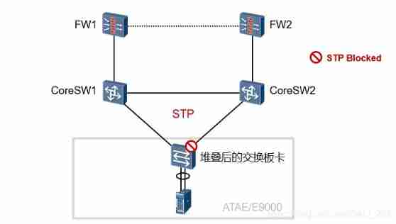
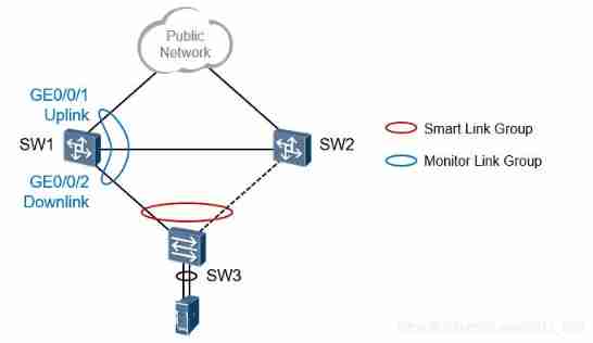
When downstream equipment is connected to upstream equipment , Single uplink mode is prone to single point of failure , Cause business interruption . Therefore, double uplink mode is usually adopted , That is, one downstream device is connected to two upstream devices at the same time , To avoid single point of failure to the greatest extent , Improve network reliability .
The dual uplink networking shown in the above figure is a common networking model , There is a triangular layer-2 loop in the switching network , The conventional solution is to use spanning tree protocol to ensure redundancy and solve the loop problem , But the convergence rate of spanning tree protocol can only reach second level at most , This is unacceptable for some sensitive businesses .
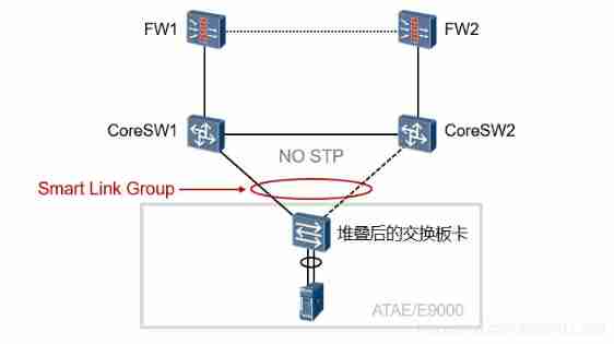
In order to meet the user's requirements for rapid link convergence and simplify the configuration , We propose Smart Link Solution , Redundant backup of primary and standby links is realized , After the failure of the primary link, the traffic can be quickly switched to the standby link , Therefore, it has a high convergence speed .
Smart Link The main features are as follows :
Dedicated to dual uplink networking ;
Fast convergence ( Sub second level );
Simple configuration , It is convenient for users to operate .
Smart Link Technical advantages
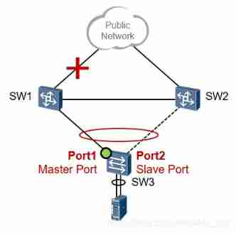
Deploy on two-way devices , When the network is normal , In the two uplinks , One is active , The other one is in the backup state ( It does not carry business traffic ). In this way, the second floor loop will be broken .
When the primary link fails , Traffic will quickly switch to the standby link in milliseconds , Ensure the normal forwarding of data .
Smart Link Simple configuration , It is convenient for users to operate .
No protocol message interaction , The convergence speed and reliability are greatly improved .
Smart Link Group
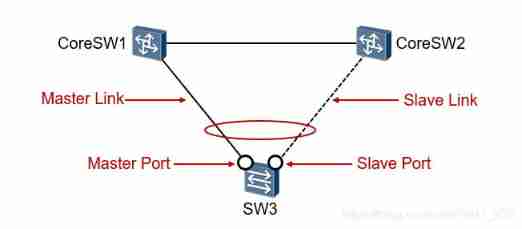
One Smart Link The group contains two member interfaces , A main interface (Master Port) And a slave interface (Slave Port). Under normal circumstances , There's only one interface (Master or Slave) Be active (Active) state , The other interface is inactive (Inactive) The state is thus blocked .
When in Active When the interface of state fails ( The faults here include interfaces down、OAM Single pass, etc ),Smart Link The group will automatically block the interface , And will be in Inactive The state of the interface is switched to Active state .
Master/Slave Interface
- Master/Slave Interface is Smart Link Two interface roles in the Group , It is specified through the command line . When both interfaces are UP when ,Master Interface into Active state , You can send and receive data , and Slave The interface is Inactive state , Prohibit sending and receiving data .
- When Master When the interface or its link fails ,Slave The interface is switched to Active state .
Master link /Slave link
- We put Master The link where the interface is located is called Master link ( Or primary link ),Slave The link where the interface is located is called Slave link ( Or backup link ).
Send control VLAN
Send control VLAN(Send Control VLAN) yes Smart Link Groups are used to send Flush The message VLAN, The VLAN Specify... By command .
If in SW3 Open the Flush Message sending function and specified sending control VLAN, So when Smart Link When the group switches , The device will start from the new main interface 、 In sending control VLAN Send inside Flush message .
Receiving control VLAN
Receiving control VLAN It is an upstream device used to receive and process Flush The message VLAN.
If upstream equipment SW1、SW2 Able to identify Flush message , And turned on Flush Message receiving and processing function , When link switching occurs , The upstream equipment will process the received, which belongs to the receiving control VLAN Of Flush message , And then perform MAC Address table entries and ARP Refresh operation of table item .
Smart Link Working mechanism
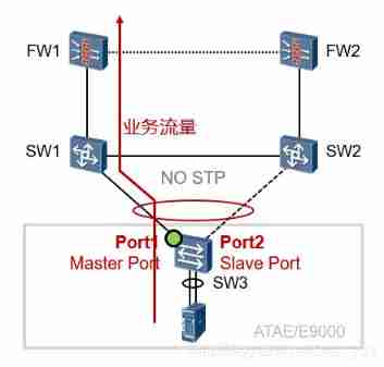
Under normal circumstances ,Master Port be in Active state , and Slave Port be in inactive state . Therefore, the business traffic is forwarded according to the path shown in the figure . At this time, there is no layer 2 loop in the network .
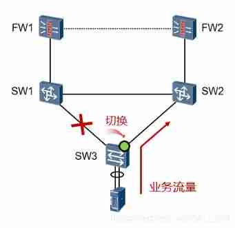
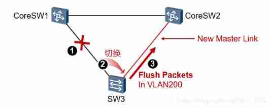
When the link shown in the figure fails ,Port1 The state of becomes Down,SW3 Immediately perceive the change and trigger Smart Link State switching ( millisecond ),Port2 Immediately transition to Active state , The uplink traffic is forwarded as shown .
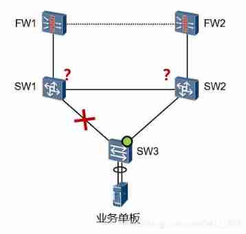
It is worth noting that , At this time, the upstream switch MAC Address table 、ARP Tables may still be entries before topology changes , Therefore, when going to the data of the business board ( Downstream traffic ) arrive SW1 or SW2 when , It may not be forwarded normally . At this point, you need to consider how to refresh SW1/SW2 Related forwarding table entries of .
Smart Link Network topology change mechanism
When Smart Link When link switching occurs , Of all devices in the network MAC Address forwarding table entries and ARP/ND Table entries may not be up-to-date , To ensure the correct sending of messages , Need to provide a MAC Address forwarding table entries and ARP/ND Update mechanism of table entries . At present, there are two update mechanisms :
from Smart Link The device sends from the new link Flush message . This method requires that all uplink devices can recognize Smart Link Of Flush Message and update MAC Address forwarding table entries and ARP/ND Processing of table items .
Automatically refresh through traffic MAC Address forwarding table entries and ARP/ND Table item . This method applies to and does not support Smart Link Functional devices ( Including equipment from other manufacturers ) Docking situation , Upstream traffic trigger is required .
Flush Mechanism
This solution requires :
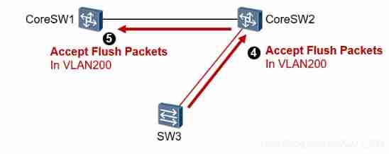
1、 Upstream switch SW1 And SW2 Able to identify Smart Link Flush message , And configure processing and receiving Flush Message control VLAN.
2、SW3 Configure send Flush Message control VLAN
SW3 happen Smart Link After link switching , It's going to be new Active Interface (Port2) send out Flush message , The purpose is to quickly refresh the upstream switch SW1 And SW2 Related forwarding table entries of .
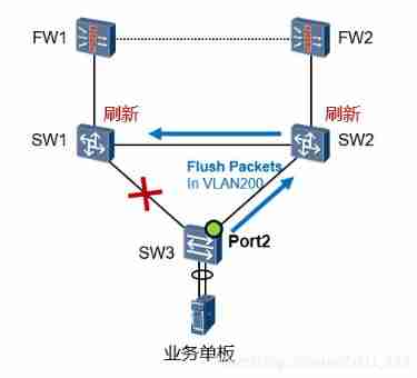
When the upstream equipment receives Flush When the message , Judge the sending control of the message VLAN Whether the receiving control of the interface receiving the message VLAN In the list . If not receiving control VLAN In the list , The device is not responsible for this Flush Messages are not processed , Forward directly ; If receiving control VLAN In the list , The device will extract Flush In the message VLAN Bitmap data , Put the equipment in these VLAN Learned in MAC And ARP Table entry deletion .
In order to ensure Flush The message is sending control VLAN Transmit correctly in , Please ensure that all interfaces on the dual uplink network allow sending control VLAN Colleague . otherwise , Flush The message will fail to be sent or forwarded .
Users are advised to keep Tag By sending Flush message , If you want to get rid of Tag By sending Flush message , Ensure that the peer interface defaults VLAN And send control VLAN Agreement , Otherwise, it will lead to Flush The message is not in transmission control VLAN Internal transmission .
Receiving is configured Flush In the case of messages ,Flush The message will trigger the device MAC Clear and ARP Aging learning action . This will take up a lot of equipment resources , In order to prevent network shock , It is not recommended to work in large-scale Smart Link Deploy receiving in the network Flush Message function .
Refresh table items through business traffic
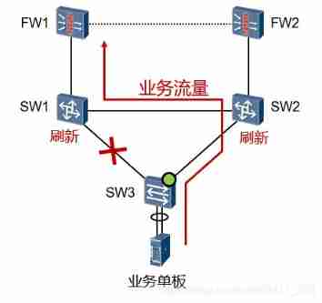
This way applies to SW3 And don't support Smart Link Functional devices ( Including equipment from other manufacturers ) Docking situation , At this time, upstream traffic is required to trigger the upstream switching device SW1 And SW2 Refresh the related table items of ( Not like it Flush That kind of active refresh ).
SW2 And SW1 After receiving the traffic sent by the service board , Refresh your related table entries .
Link recovery mechanism
When Smart Link In the group Master Port When it breaks down ,Slave Port Will automatically switch to Active state . When Master Port After recovery , In order to keep the flow stable , It will remain at Inactive state , No preemption . If you need to restore it Active, It can be achieved in the following two ways :
Can make Smart Link Group failback function . After the failback timer expires, the main link will be automatically switched .
Use smart-link manual switch Command forced link switching .
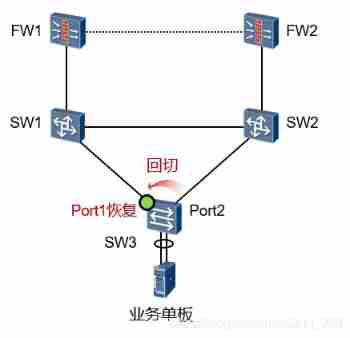
if SW3 Of Smart Link Group activation failback function :
be Master Interface Port1 After recovering from a failure , Will be carried out in “ Role preemption ”, At a certain time delay ( default 60s) After the transition to Active state , and Port2 Then transition to Inactive state .
if SW3 Of Smart Link Group does not activate failback ( Not activated by default ):
be Master Interface Port1 After recovering from a failure , No state switching , Unless Port2 failure , Otherwise, maintain at Inactive state .
Basic configuration
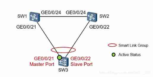
There is a triangular layer-2 loop in the network , stay SW3 Upper Department Smart Link,GE0/0/21 Configure to Master Port,GE0/0/22 Configure to Slave Port. When the network is normal , By default, the business flow is from GE0/0/21 Interface forward , When the interface fails , Auto switch to GE0/0/22. When GE0/0/21 Recover from failure , Then the flow is switched back to GE0/0/21 Interface .
Intranet business VLAN by 10 And 20.
VLAN99 by Smart Link control VLAN
SW3 To configure :
[SW3]vlan batch 10 20 99
#  stay Smart Link Close on the group member interface STP:
[SW3]interface GigabitEthernet 0/0/21
[SW3-GigabitEthernet0/0/21]stp disable
[SW3]interface GigabitEthernet 0/0/22
[SW3-GigabitEthernet0/0/22]stp disable
#  The configuration interface type is trunk And release relevant VLAN( user VLAN And control VLAN)
[SW3]interface GigabitEthernet 0/0/21
[SW3-GigabitEthernet0/0/21]port link-type trunk
[SW3-GigabitEthernet0/0/21]port trunk allow-pass vlan 10 20 99
[SW3]interface GigabitEthernet 0/0/22
[SW3-GigabitEthernet0/0/22]port link-type trunk
[SW3-GigabitEthernet0/0/22]port trunk allow-pass vlan 10 20 99
( The system view ) establish Smart Link Group 1
[SW3]smart-link group 1
#  To configure Master And Slave Interface :
[SW3-smlk-group1]port GigabitEthernet 0/0/21 master
[SW3-smlk-group1]port GigabitEthernet 0/0/22 slave
#  Configure send control VLAN(99)
[SW3-smlk-group1]flush send control-vlan 99
#  Activate the failback function :
[SW3-smlk-group1]restore enable
[SW3-smlk-group1]timer wtr 30       # Wait-to-restore, default 60s
[SW3-smlk-group1]smart-link enable
SW1 and SW2 To configure :
SW1:
[SW1]vlan batch 10 20 99
[SW1]interface GigabitEthernet 0/0/21
[SW1-GigabitEthernet0/0/21]port link-type trunk
[SW1-GigabitEthernet0/0/21]port trunk allow-pass vlan 10 20 99
[SW1-GigabitEthernet0/0/24]stp disable                  #  close stp
[SW1-GigabitEthernet0/0/21]smart-link flush receive control-vlan 99 #  Allow reception control vlan data
[SW1]interface GigabitEthernet 0/0/24
[SW1-GigabitEthernet0/0/24]port link-type trunk
[SW1-GigabitEthernet0/0/24]port trunk allow-pass vlan 10 20 99
[SW1-GigabitEthernet0/0/24]stp disable
[SW1-GigabitEthernet0/0/24]smart-link flush receive control-vlan 99
SW2:
[SW2]vlan batch 10 20 99
[SW2]interface GigabitEthernet 0/0/22
[SW2-GigabitEthernet0/0/22]port link-type trunk
[SW2-GigabitEthernet0/0/22]port trunk allow-pass vlan 10 20 99
[SW2-GigabitEthernet0/0/22]stp disable
[SW2-GigabitEthernet0/0/22]smart-link flush receive control-vlan 99
[SW2]interface GigabitEthernet 0/0/24
[SW2-GigabitEthernet0/0/24]port link-type trunk
[SW2-GigabitEthernet0/0/24]port trunk allow-pass vlan 10 20 99
[SW2-GigabitEthernet0/0/24]stp disable
[SW2-GigabitEthernet0/0/24]smart-link flush receive control-vlan 99
see smart Group Information
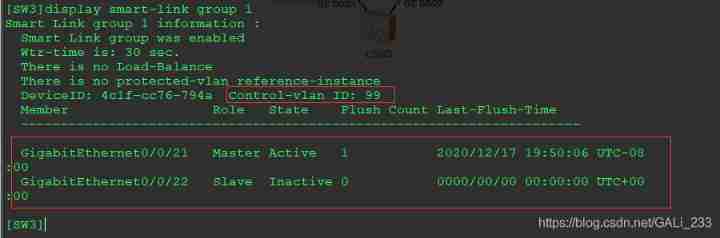
Turn off the interface test
[SW3]interface GigabitEthernet 0/0/21
[SW3-GigabitEthernet0/0/21]shutdown
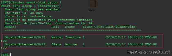
After topology change ,G0/0/22 Will be sent in control vlan99 send out Flush package , Let the upper device refresh the topology
Monitor Link
Technical background
SW3 Deployed Smart Link Group , stay Port1 When the link to which it is connected fails ,Smart Link Be able to sense and realize fast switching , But when SW1 When the uplink link of fails ,Smart Link But I can't feel , There will be no switching .
Monitor Link It's right Smart Link A powerful complement to technology .Monitor Link Used to monitor the uplink , To achieve the purpose of synchronizing the downlink with the uplink state , send Smart Link The backup function of is more perfect .
Monitor Link Technical realization
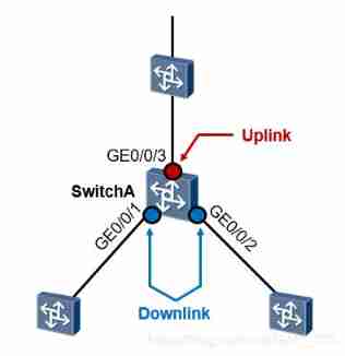
Monitor Link Groups are also called monitoring link groups , By one or more uplink (Uplink) And down (Downlink) Interface composition . The state of the downlink interface changes with the state of the uplink interface .
Uplink interface (Uplink Port) yes Monitor Link Monitoring objects in the Group , It is specified through the command line Monitor Link An interface role of a group .
If multiple interfaces are configured as Monitor Link Group uplink interface , As long as one of these interfaces is in forwarding state , that Monitor Link The status of the group is UP;
Only when all The uplink interface fails when ,Monitor Link The status of the group is Down, At this time All downlink interfaces will be closed . When Monitor Link When the uplink interface of the group is not specified , It is considered that the uplink interface is faulty , All downlink interfaces will be closed .
Downlink interface (Downlink Port) yes Monitor Link Monitors in the Group , It is specified through the command line Monitor Link Another interface role of the Group .Monitor Link The downlink interface of the group can be Ethernet interface ( Electric port or optical port ) Or aggregate interface .
When Monitor Link When the uplink interface of the group returns to normal ,Monitor Link Only the downlink interface blocked due to uplink interface failure will be opened , The manually closed downlink interface cannot be opened . And a downlink interface failure has no impact on the uplink interface and other downlink interfaces .
Basic configuration
SW1 The configuration is as follows :
( The system view ) establish monitor link Group :
monitor-link group 1
    # To configure monitor link Group uplink interface :
    port gigabitethernet0/0/1 uplink
    # To configure monitor link Downlink interface of the Group :
    port gigabitethernet0/0/2 downlink
边栏推荐
- PHP high concurrency and large traffic solution (PHP interview theory question)
- What are the domestic formal futures company platforms in 2022? How about founder metaphase? Is it safe and reliable?
- Basic JSON operations of MySQL 5.7
- 复现Thinkphp 2.x 任意代码执行漏洞
- Coding devsecops helps financial enterprises run out of digital acceleration
- Bugku's eyes are not real
- Bugku's steganography
- I'm fat, huh
- Install PHP extension spoole
- Xiao Sha's arithmetic problem solving Report
猜你喜欢
I include of spring and Autumn

First PR notes
Optional parameters in the for loop
Summary of the second lesson

Codasip为RISC-V处理器系列增加Veridify安全启动功能
CSRF, XSS science popularization and defense

No one consults when doing research and does not communicate with students. UNC assistant professor has a two-year history of teaching struggle
Thymeleaf uses background custom tool classes to process text

Example of lvgl display picture
爱可可AI前沿推介(7.5)
随机推荐
The computer is busy, and the update is a little slow
ICML 2022 | 探索语言模型的最佳架构和训练方法
How to introduce devsecops into enterprises?
lvgl 显示图片示例
Creation and use of thymeleaf template
30岁汇源,要换新主人了
超越PaLM!北大硕士提出DiVeRSe,全面刷新NLP推理排行榜
How to paste the contents copied by the computer into mobaxterm? How to copy and paste
一文搞定vscode编写go程序
Common PHP interview questions (1) (written PHP interview questions)
当代人的水焦虑:好水究竟在哪里?
wxml2canvas
What are CSRF, XSS, SQL injection, DDoS attack and timing attack respectively and how to prevent them (PHP interview theory question)
Common MySQL interview questions
Huiyuan, 30, is going to have a new owner
Xiao Sha's arithmetic problem solving Report
Crud de MySQL
Can gbase 8A view the location of SQL statement history?
Ctfshow web entry explosion
Common redis data types and application scenarios