当前位置:网站首页>FLIR blackfly s industrial camera: configure multiple cameras for synchronous shooting
FLIR blackfly s industrial camera: configure multiple cameras for synchronous shooting
2022-07-07 02:00:00 【The moon shines on the silver sea like a dragon】
Flir Blackfly S Industrial camera : Configure multiple cameras for synchronous shooting
Flir Blackfly S Introduction to industrial camera
Blackfly S Adopt the advanced ice shape sensor in the industry .
It's powerful , You can easily generate the exact image you need , And accelerate application development .
Including automatic and precise manual control of image capture and camera preprocessing .
Blackfly S Provide GigE、USB3、 Suit and board versions .
Accurate image SONY CMOS Choices among sensors include : Global shutter 、 Polarization and high sensitivity BSI sensor .
The physical drawing is as follows :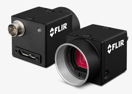
Synchronous shooting concept
Synchronous shooting refers to two or more cameras capturing images at the same time
“ meanwhile ” It means that the camera must start exposing each group of images within a few microseconds
Here is how to use the strobe of the main camera ( When the camera starts capturing images, there is a strobe by default ) Through one “ Lord ” The camera triggers another or more “ vice ” camera . This also ensures that the frame rate of the sub camera is the same as that of the main camera .
Another method can also trigger multiple cameras by external hardware at the same time to achieve the above functions
Synchronously shoot application scenes
The synchronous shooting application can be spliced with multiple cameras , Or multi camera detection in the field of autonomous driving . For example, the camera carrier moves faster , The exposure time deviation of multiple cameras is large , There will be no splicing . So synchronous shooting is still very important in application .
Flir Blackfly S Synchronous shooting method
The synchronous shooting method is mainly divided into two steps :
- Connect the camera GPIO Pin , Establish hardware connection between cameras .
- Use SDK Demonstrate the application or code to configure the input and output of each camera .
Next, we will introduce each step in detail
Establish hardware connection between cameras
The first step is to establish a hardware connection between cameras .
Blackfly S (BFS ) The camera is equipped with a 6 The needle GPIO. BFS GPIO At the same time, it is equipped with a non isolated output and a photoelectric isolated output . If photoelectric isolation output is used , The main camera needs a pull-up resistor to enhance its flash signal .
BFS The camera is equipped with a 6 The needle GPIO The definition is as follows 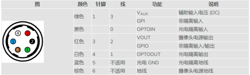
You want to configure BFS Main camera and sub camera :
- Turn the number of the main camera 4 The needle ( White line , Photoelectric isolation output ) Connected to the No. of each sub camera 1 The needle ( The green line , Non isolated input ).
- Turn the number of the main camera 5 The needle ( The blue line , Photoelectric isolation ground wire ) Connected to the No. of each sub camera 6 The needle ( Brown line , Ground wire ).
To configure the required pull-up resistance to enhance the signal :
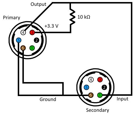
- take 10 kΩ One end of the resistor is connected to the first... Of the main camera 3 The needle ( Red thread ,3.3 V Output ).
- Connect the other end of the resistor to the second end of the main camera 4 The needle ( White line ) And the number of each sub camera 1 The needle ( The green line ).
- Turn the number of the main camera 6 The needle ( Brown line ) Connected to the No. of each sub camera 6 The needle ( Brown line ). Be careful : Sub camera No 6 The pin is connected to the... Of the main camera 5 The needle .
Configure the camera software
After hardware connection of each camera , Use Upper computer To configure the GPIO Line .
The upper computer is SpinView
Main camera
- open SpinView.
- Select the camera .
- On the function tab , Click number IO control .
- Select... From the line selection drop-down menu line 1, Then set the line mode to output .
- Enable 3.3V Line select a line from the line selection drop-down menu 2, And check the 3.3V Enable the check box
- Save settings in user settings
Secondary camera
- open SpinView And select the camera .
- choice GPIO tab . Set trigger source from the trigger source drop-down menu , choice line 3.
- From the trigger overlap pull list , Select read .
- From the trigger mode drop-down list , Choose to open .
- Save settings in user settings
Start saving images at the same time
After configuring the main camera and sub camera , You can start saving the synchronized image .
If you save images with high bandwidth , It is recommended to use the controller application instead of the upper
If you use SpinView The method is as follows :
- Make sure that the trigger mode of the main camera is turned on .
- In the streaming window of the main camera , Click the record button .
- Modify the recording settings as needed .
- Click the start recording button .
- Keep the recording window open .
- For the sub camera , Repeat the first 1 Step to the top 5 Step .
- Turn off the trigger mode of the main camera . This will start the shooting of two cameras .
If you use your own controller, you can combine Spinnaker SDK Example code for
AcquisitionMultipleCameraTrigger
Position in Example: C:\Program Files\Point Grey Research\Spinnaker\src
When using these cameras for synchronous shooting , The flash must be turned on . Turn on strobe , You can use the following code to create a StrobeControl Structural examples :
StrobeControl strobe;

strobe.source = 2;

error = cam.GetStrobe(&strobe);

strobe.onOff = true;

error = cam.SetStrobe(&strobe);
Problems encountered and Solutions
The frame rate of the sub camera when capturing images is half that of the main camera
** reason :** The secondary camera does not use overlap trigger
** Solution :** On the auxiliary camera , Switch to using “ Trigger overlap ”.
The sub camera takes images at a very low frame rate
** reason :** Camera exposure ( Shutter ) The value is too large .
** Solution :** Exposure can be adjusted ( Shutter ) Time .
stay SpinView in Settings On the tab
边栏推荐
- AcWing 1148. Secret milk transportation problem solution (minimum spanning tree)
- How to use strings as speed templates- How to use String as Velocity Template?
- C语言【23道】经典面试题【下】
- Public key \ private SSH avoid password login
- The cradle of eternity
- ROS learning (XIX) robot slam function package cartographer
- Centos8 install MySQL 8.0 using yum x
- 一片叶子两三万?植物消费爆火背后的“阳谋”
- Shell script quickly counts the number of lines of project code
- Appium基础 — Appium Inspector定位工具(一)
猜你喜欢

百度飞将BMN时序动作定位框架 | 数据准备与训练指南 (上)
AcWing 345. Cattle station solution (nature and multiplication of Floyd)
According to the analysis of the Internet industry in 2022, how to choose a suitable position?
454-百度面经1

The difference between Tansig and logsig. Why does BP like to use Tansig
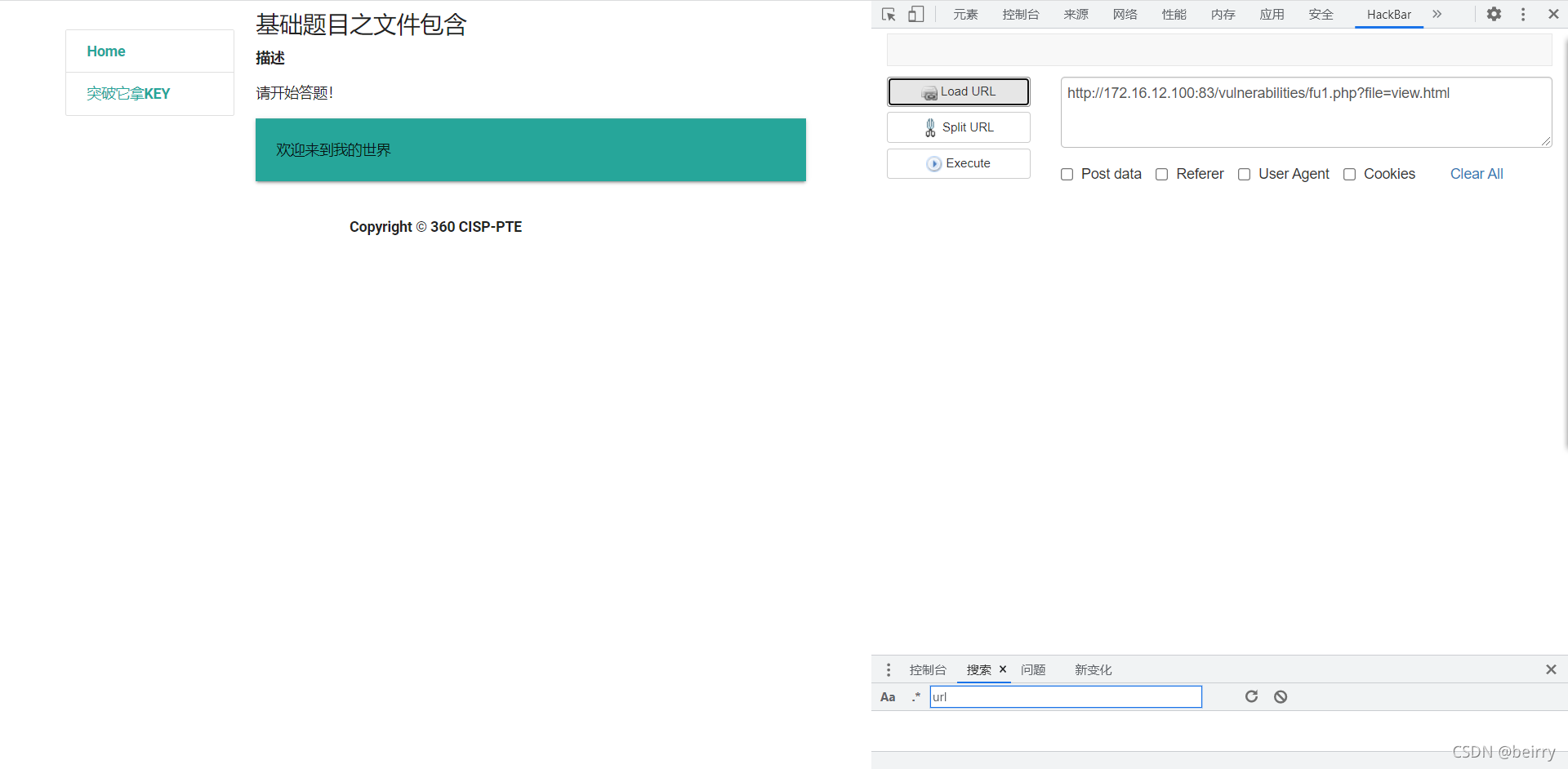
Cisp-pte practice explanation (II)
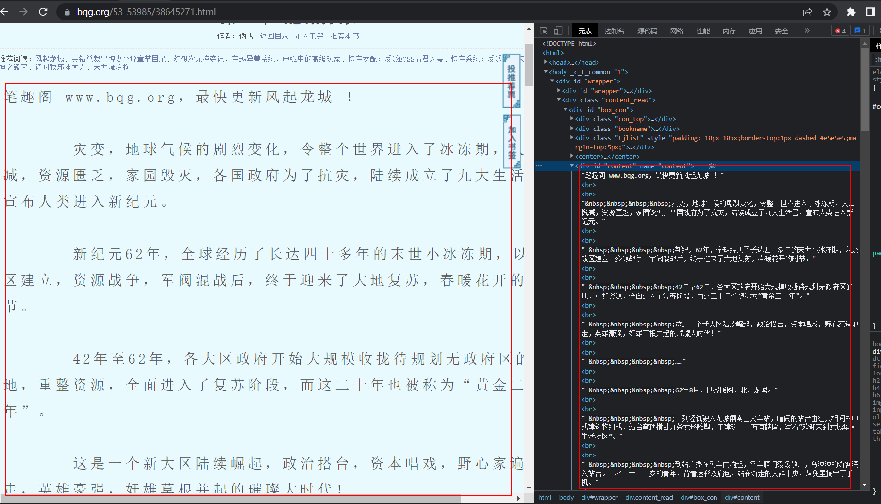
Reptile practice (VI): novel of climbing pen interesting Pavilion
Ros Learning (23) Action Communication Mechanism
Basic introduction and use of dvajs
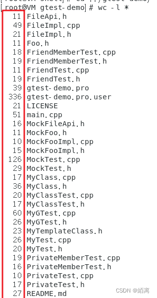
Shell script quickly counts the number of lines of project code
随机推荐
Shell script quickly counts the number of lines of project code
Telnet,SSH1,SSH2,Telnet/SSL,Rlogin,Serial,TAPI,RAW
Gin 入门实战
HDU 4661 message passing (wood DP & amp; Combinatorics)
sql中批量删除数据---实体中的集合
AcWing 1141. LAN problem solving (kruskalkruskal finding the minimum spanning tree)
ROS learning (24) plugin
一片叶子两三万?植物消费爆火背后的“阳谋”
Make DIY welding smoke extractor with lighting
拖拽改变顺序
ROS学习(二十)机器人SLAM功能包——rgbdslam的安装与测试
Mysqlbackup restores specific tables
grep查找进程时,忽略grep进程本身
AcWing 344. Solution to the problem of sightseeing tour (Floyd finding the minimum ring of undirected graph)
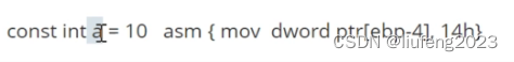
JS es5 peut également créer des constantes?
Yiwen takes you into [memory leak]
[unique] what is the [chain storage structure]?
Reptile practice (VI): novel of climbing pen interesting Pavilion
Cisp-pte practice explanation (II)
【唯一】的“万字配图“ | 讲透【链式存储结构】是什么?