当前位置:网站首页>FPGA course: application scenario of jesd204b (dry goods sharing)
FPGA course: application scenario of jesd204b (dry goods sharing)
2022-07-07 07:07:00 【MDYFPGA】
This article is an original article by Ming Deyang , Reprint please indicate the source !
One ,JESD204B Advantages and disadvantages of application
Come into contact with FPGA High speed data Collect design friends , I should have heard of new terms “JESD204B”. This is a new type based on high speed SERDES Of ADC/DAC Data transmission interface . With ADC/DAC The sampling rate is getting higher and higher , The throughput of data is getting bigger and bigger , about 500MSPS The above ADC/DAC, There are dozens of them G Data throughput of , If you still use the traditional CMOS and LVDS It has been difficult to meet the design requirements , therefore “JESD204B” emerge as the times require . Now the high speed of major manufacturers ADC/DAC Basically, this kind of interface is used .
And LVDS And CMOS Interface comparison ,JESD204B data The converter serial interface standard provides some significant advantages , For example, simpler layout and fewer pins . Therefore, it has won the favor and attention of more engineers , It has the following system level advantages :
1、 Smaller package size and lower package cost :JESD204B Not only with 8b10b Coding technology serial packaging data , It also helps support up to 12.5Gbps The data rate of . Significantly reduce data converters and FPGA Number of pins required on , This can help reduce the package size , Reduce packaging costs ;
2、 A simplified PCB Layout and routing : Fewer pins can significantly simplify PCB Layout and routing , Because there are fewer paths on the circuit board . As the demand for distortion management decreases , Therefore, the layout and wiring can be further simplified . This is because the data clock is embedded in the data stream , And it is combined with elastic buffer in the receiver , There is no need to pass “ wavy curve ” To match the length . The picture below is JESD204B Interface pair simplification PCB Examples of how helpful layout is ;
3、 Highly flexible layout :JESD204B Low requirements for distortion , It can realize longer transmission distance . This helps to deploy logic devices further away from the data converter , In order to avoid the impact on sensitive simulators ;
4、 Simpler timing control ;
5、 Meet future needs : The interface can adapt to different data converter resolutions . For future analog-to-digital converters (ADC) And digital to analog converter (DAC) for , There is no need to be right TX/RX The circuit board is physically redesigned .

chart :LVDSDAC Of PCB Layout ( Left ); use JESD204B In the same DAC Of PCB Layout ( Right )
The following table is JESD204B、LVDS The contrast between interfaces :

since JESD204B There are so many advantages of interfaces , Does this mean that everyone should choose JESD204B Interface What about it ?
not always . And LVDS Interface comparison ,JESD204B The disadvantage of is that it has a longer absolute delay , This is unacceptable for some applications .
Even though JESD204B Can provide many advantages , But some applications require very short delay , It is better to have no time delay . A good example is the signal shield used in electronic warfare . The device requires not only absolute time delay , And you need to minimize any possible delays .
For this application , You should still consider using LVDS Interface , So it's not in JESD204B The delay of data serialization on .
Two ,JESD204B Introduction to the agreement
1、 What is? JESD204B agreement
This standard describes the converter and the devices connected to it ( It's usually FPGA and ASIC) Number between GB Class a serial data link , In essence , It has the function of high-speed parallel serial conversion .
2、 Use JESD204B Reason for interface
a. No longer use the data interface clock ( The clock is embedded in the bitstream , Using recovery clock technology CDR)
b. Don't worry about channel offset ( Channel alignment fixes this problem ,RX End FIFO Buffer )
c. Don't use too much IO mouth , Wiring is convenient ( High speed serial deserializer achieves high throughput )
d. Multiple slices IC Convenient synchronization
JESD204A and JESD204B The parameter comparison is shown in the following figure :

3、 Key variables
M:converters/device, converter (AD/DA) Number
L:lanes/device(link), Number of channels
F:octets/frame(perlane), Every frame 8 Number of bits and bytes
K:frames/multiframe, The number of frames per frame
N:converterresolution, Converter resolution
N’:totalbits/sample,4 Multiple ,N’=N+ Control and pseudo data bits .
S:samples/converter/framecycle, The number of samples sent by each converter per frame . When S=1 when , Frame clock = Sampling clock
CS:controlbits/sample
CF:controlwords/framecycle/device(link), Usually only in HD=1 When using .
4、subclass0~2 Determine the delay
subclass0: Definite delay is not supported ;
subclass1:SYSREF,(AD9370 It supports subclasses 1,IP The kernel is also a subclass by default 1), Use the determined delay to align multiple slices IC;
subclass2:SYNC~.
5、subclass1 Three stages of
A、 The first stage , Code group synchronization (CGS)
a、RX take SYNC~ Pin down , Send a synchronization request .
b、TX Start with the next symbol , Send undisturbed /K28.5/ Symbol ( Every symbol 10 position ).
c、 When RX Received at least 4 An error free continuous /K28.5/ The symbol ,RX Sync , And then SYNC~ The pins are pulled up .
d、RX Must receive at least 4 No mistakes 8B/10B character , Otherwise, synchronization will fail , The link remains CGS Stage .
e、CGS End of the stage ,ILAS The stage begins .
Be careful :
a、 Serial data transmission has no interface clock , therefore RX Its digits and word boundaries must be aligned with TX Serial output alignment .RX towards TX send out ~SYNC Request signal , Let it send a known repeated bit sequence through all channels K28.5.RX Bit data on each channel will be moved , Until I find 4 A continuous K28.5 Until the character . here , It will not only know the bit and word boundaries , And it's done CGS.
b、RX~SYNC The output of must be consistent with RX Frame clock synchronization , Simultaneous requirements TX Frame clock and ~SYNC Sync ( It can be done by ~SYNC Reset TX Frame clock counter ).
c、 AC coupling cannot be used .
B、 The second stage , Initial channel synchronization (ILAS):
a、 stay JESD204B in , The sending module captures SYNC~ Signal transformation , In the next local multi frame (LMFC) Start on the boundary ILAS.
b、ILAS Mainly align all channels of the link , Verify link parameters , And determining the position of the frame and multi frame boundary in the input data stream of the receiver .
c、ILAS from 4 Multiple frames . The last character of each multi frame is the multi frame alignment character /A, First of all , 3、 ... and , Four multiple frames in /R Character start , With /A End of character . The receiver takes the last character of each channel /A Align the ends of multiple frames in each channel in the receiver .
d、 These specific control characters are only used in the initial path alignment sequence , Not at any other stage of data transmission .CGS and ILAS The stage is undisturbed .
e、RX Module FIFO Absorption channel offset .
C、 The third stage , Data transmission phase :
There are no control characters , Obtain the full bandwidth of the link . Use character substitution to monitor data synchronization , Multi frame counter LMFC.
6.Deviceclk
System reference clock , Provide sampling clock ,JESD204B The clock , Frame serializer clock . Generate frame clock and multi frame clock . Device clock is used to capture SYSREF, And complete the front phase alignment of frame and multi frame clock . Subclass 1 in , The multi frame clock cycle must be an integral multiple of the device clock .ADC/DAC/FPGA It can run at different speeds , But it must be homologous and frequency related .
7、 Synchronize the alignment process
The transmitter and receiver each maintain a multi frame counter (LMFC), All transmitters and receivers are connected to a common ( Source )SYSREF, These devices utilize SYSREF Reset its LMFC, That all LMFC Should be synchronized with each other ( In a clock cycle ).
SYSREFsignal(DeviceSubclass1):
a、 Time delay determination ( Less than 1 Multiple frame clock cycles ).
b、 The alignment is homologous with the device clock ,LMFC An integral multiple of a period , stay DeviceClk Sample as it changes SYSREF The signal , Time delay determination , Align multiple frames and frame clocks .SYSREF Used to align all transceiver devices LMFC phase .
SYNC~signal:
Synchronization request signal . The receiver : Synchronize with the receiver frame clock .CGS Then at the receiving end LMFC The edge is raised . Release SYNC( All devices will see ) after , The transmitter is next (TX)LMFC Bypass 0 Start when ILAS. If F*K Set appropriate , Greater than ( Transmitter coding time )+( Line propagation time )+( Receiver decoding time ), Then the received data will be in the next LMFC Previously from the receiver SERDES Spread it out . The receiver will send data into FIFO, And then next (RX)LMFC The boundary starts to output data . transmitter SERDES Input and receiver FIFO The known relationship between outputs is called deterministic delay .
3、 ... and ,JESD204B Specific application examples
1、 Application of phased array radar downlink synchronous acquisition technology
The synchronous acquisition of multi-channel data is the key problem to be solved in the downlink data receiving and processing of digital phased array radar . Proposed support JESD204B agreement Analog to digital converter and support JESD204B Agreed FPGA Design scheme combining soft core . utilize JESD204B Deterministic delay characteristics of the Protocol , As long as the mutual delay of downlink data between channels is not more than one multi frame clock cycle , Through the design and processing of key control signals , Data synchronization can be realized between channels , There are many pieces in the effective control board ADC Synchronous sampling between , So as to solve the phase consistency problem caused by the acquisition of digital phased array radar downlink data .
2、 Realization of radar multi-channel synchronous acquisition
The design is a simplified scheme combining software and hardware , Through reasonable design of hardware 、 Design SYSREF Fan out control logic of signal , Within a certain sampling rate range JESD204B agreement ADC The relative delay of sampling points between multiple slices and channels is fixed , So as to ensure that the phase of the collected signals of each channel is consistent .JESD204B agreement The deterministic delay feature supported ensures the design implementation . The test circuit of the verification scheme adopts Xilinx K7 series FPGA Control two pieces AD9694( Sampling rate 320Msps) Synchronous acquisition , Verify that the design scheme meets the application requirements .
3、 Design and implementation of synchronous transmission of radar video signal
Taking the multi beam amplitude comparison DF in the broadband DF receiver as the background , Designed based on JESD204B High speed backplane video signal synchronous transmission scheme of the Protocol . The clock 、JESD204B The design of protocol parameters is reasonable , Realized 2 Block multi-channel video amplitude acquisition board and 1 The linear rate between the data processing boards is 6.25Gbps High speed synchronous transmission , It solves the problem of multi-channel video signal transmission synchronization before multi beam amplitude comparison measurement .
4、 High speed ADC Application and research
In imaging equipment 、 signal communication 、 radar 、 Industrial instruments and other industries that need to transmit a large amount of data in real time , The sampling rate of its digital to analog converter is required to be higher and higher 、 The data bits are getting bigger 、 The bandwidth is getting wider 、 The transmission rate is getting faster and faster . This puts forward higher requirements for high-speed data acquisition and transmission system . Conventional ADC Most of them use parallel bus for data transmission , With the increase of sampling rate , The surge in the amount of captured data , The throughput of parallel bus needs to be greatly improved , This requires increasing the number of bits of the output data line , And the increase of bits requires a lot of chip pins , Make the chip and PCB It is difficult to realize the miniaturization of and control voltage noise while routing a large number of high-speed data signals .
With traditional parallel bus transmission ADC comparison , Using high-speed serial bus transmission ADC It has a very obvious advantage , The required signal transmission lines are greatly reduced , The bus transmission rate is also significantly improved , And it saves wiring space while improving the data transmission rate , At the same time, it also reduces the power consumption of the chip . Using high-speed serial bus transmission ADC Not only in volume 、 Power consumption and data transmission rate are higher than those of parallel bus transmission ADC More advantage . In the high-speed data acquisition and transmission system , Serial bus transmission ADC It has become the development trend in the future . After studying the high-speed serial transmission technology , Designed based on JESD204B Protocol serial bus technology ADC, And designed a high-speed based on this Protocol ADC Sampling circuit , The analog-to-digital conversion chip supports JESD204BSubclass1 Working mode , adopt FMC Interface and high performance FPGA Of GTH The interface is connected to receive ADC Sampled data , Finally through PCIE Golden finger and PC End for transmission .
5、JESD204B Design and implementation of auto Synchronous Scrambling and descrambling circuit in the Protocol
As JEDEC The latest revision of AD/DA Serial transmission protocol ,JESD204B Adopt self synchronous scrambling code to randomize the raw signal of data link layer , It effectively avoids the generation of spurious spectrum , Reduce the bit error probability of physical layer . Based on the classical state machine structure JESD204B agreement Design and implement the auto Synchronous Scrambling and descrambling circuit in , According to the principle of self synchronization scrambling in the Protocol , A design scheme of scrambling and descrambling state circuit is proposed , Finally, the scheme is implemented 、 Simulation and synthesis . Simulation and synthesis results show that the scheme is fully compatible with the protocol control signal , The function fully meets the requirements of the agreement , The stability and fault tolerance of the scrambling and descrambling circuit are enhanced , At the same time, the processing efficiency of the circuit is improved , It can be applied to JESD204B High speed serial interface circuit design .
That's about JESD204B Introduction of application scenarios , Mingdeyang can undertake based on JESD204B High speed data transmission project , To learn more , Contact .
边栏推荐
猜你喜欢
![[noi simulation] regional division (conclusion, structure)](/img/7d/4c66cd0a30e52ccd167b6138fcb4df.png)
随机推荐
Mysql---- import and export & View & Index & execution plan
Learning records on July 4, 2022
【mysqld】Can't create/write to file
工具类:对象转map 驼峰转下划线 下划线转驼峰
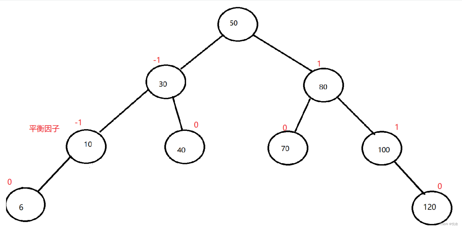
AVL树的实现
毕业设计游戏商城
华为机试题素数伴侣
Brand · consultation standardization
MATLAB小技巧(30)非线性拟合 lsqcurefit
MYSQL binlog相关命令
$refs:组件中获取元素对象或者子组件实例:
什么情况下考虑分库分表
From zero to one, I will teach you to build the "clip search by text" search service (2): 5 minutes to realize the prototype
带你刷(牛客网)C语言百题(第一天)
企业如何进行数据治理?分享数据治理4个方面的经验总结
Maze games based on JS
DB2获取表信息异常:Caused by: com.ibm.db2.jcc.am.SqlException: [jcc][t4][1065][12306][4.25.13]
unity3d学习笔记
2018 Jiangsu Vocational College skills competition vocational group "information security management and evaluation" competition assignment
How does an enterprise manage data? Share the experience summary of four aspects of data governance