当前位置:网站首页>Design of kindergarten real-time monitoring and control system
Design of kindergarten real-time monitoring and control system
2022-07-05 02:31:00 【Salted fish brother】
word The full version can be downloaded as follows >>>>>>>>
Objective record
Abstract ----------------------------------------------------------------- I
ABSTRACT------------------------------------------------------------ II
1 The introduction -------------------------------------------------------------- 1
1.1 Research background and significance ---------------------------------------------- 1
1.2 Research status at home and abroad -------------------------------------------- 1
1.3 Main contents of this paper ------------------------------------------------ 2
2 The overall design of the system ---------------------------------------------------- 3
2.1 Systematic research tasks ---------------------------------------------- 3
2.2 System structure design ------------------------------------------------ 3
3 System hardware design ------------------------------------------------------ 5
3.1 Control system module ------------------------------------------------ 5
3.2 Power module ---------------------------------------------------- 6
3.3 Temperature sensor module ---------------------------------------------- 7
3.4 Smoke sensor module ---------------------------------------------- 8
3.5 Positioning monitoring module ----------------------------------------------- 10
3.6 Image acquisition module ----------------------------------------------- 10
3.7 Wireless communication module ----------------------------------------------- 11
3.8 Display module --------------------------------------------------- 12
3.9 Overall circuit diagram of the system --------------------------------------------- 13
4 System software design ----------------------------------------------------- 14
4.1 Main program design ------------------------------------------------- 14
4.2 Software design of temperature sensor --------------------------------------- 15
4.3 Software design of smoke sensor --------------------------------------- 16
4.4 Design of location monitoring software ----------------------------------------- 17
4.5 Image acquisition software design ------------------------------------------- 18
4.6 WIFI Module software design ---------------------------------------- 20
4.7 Connection of mobile phone ----------------------------------------------- 21
5 System debugging --------------------------------------------------------- 23
5.1 Physical test --------------------------------------------------- 23
5.2 test result --------------------------------------------------- 24
6 Summary and prospect ------------------------------------------------------- 25
6.1 summary ------------------------------------------------------- 25
6.2 expectation ------------------------------------------------------- 25
reference ------------------------------------------------------------ 26
thank ---------------------------------------------------------------- 28
appendix ---------------------------------------------------------------- 29
pick want
Kindergarten education is based on safety , Only in a safe environment , We can talk about children's education and growth . It is related to the happiness of thousands of families and the long-term development and future of the country . In recent years , Various safety accidents often happen in kindergartens , The life safety and healthy growth of children are seriously threatened , We must attach great importance to children's life and health . Kindergartens are places for teaching and educating people , The safety guarantee of kindergartens is the basis of teaching and educating people .
This design mainly adopts STM32 Embedded is the core of processor , Use wireless communication ESP8266 And various sensors constitute a real-time monitoring and control system covering the whole campus . Realize temperature and humidity control through the mobile terminal 、 smoke 、 Real time monitoring of location and various states of students , And pass STM32 Set temperature and humidity 、 The smoke threshold control relay is switched on and off to control the power supply . At the same time, the system realizes the control relay of mobile terminal .
STM32 Main control circuit , Using temperature and humidity sensors DHT11 To monitor the temperature and humidity , When the temperature and humidity are too high, the system turns on the air conditioner , Create a comfortable classroom environment for children ; Use the smoke sensor to monitor the smoke concentration , When the smoke concentration is too high, control the exhaust fan to exhaust and alarm , To prevent fire ; Using RFID Technology KL4000 Design child positioning , Prevent children from getting lost ; utilize CMOS series OV7725 The camera completes the collection of various states in the children's room , Real time acquisition and transmission to the mobile terminal .
key word : Intelligent monitoring RFID Technology Remote control
ABSTRACT
Kindergarten education is all based on safety and only in a safe environment can we talk about the education and development of children. It is a matter of the well-being of thousands of families and the long-term development and future of the country. In recent years, various safety accidents have often occurred in kindergartens, and the safety and healthy growth of young children has been seriously threatened, and we must pay great attention to the lives and health of children. Kindergarten is a place for teaching and educating people, and the safety and security of kindergarten is the foundation of teaching and educating people.
The design mainly adopts STM32 embedded as the processor core, using wireless communication ESP8266 and various sensors to form a real-time monitoring control system covering the whole campus. Through the mobile phone terminal to achieve the monitoring of temperature and humidity, smoke, real-time location and various states of students, and through the STM32 set temperature and humidity, smoke threshold control relay suction to control the power on and off. The system also implements a mobile phone terminal to control the relays.
STM32 is the main control circuit, using the temperature and humidity sensor DHT11 to monitor the temperature and humidity degree, the system turns on the air conditioning when the temperature and humidity is too high to create a comfortable classroom environment for children; using the smoke sensor to monitor the smoke concentration, when the smoke concentration is too high to control the exhaust fan for exhaust and alarm to prevent fire; using the radio frequency identification technology KL4000 to design the positioning of children to prevent Using the CMOS series OV7725 camera to complete the collection of various states of the children's room, real-time collection and transmission to the mobile phone terminal.
Keywords: Intelligent Monitoring RFID Remote control
1 The introduction
1.1 Research background and significance
The development and implementation of the national medium and long-term curriculum has increased the importance of preschool education , The importance of preschool education has been recognized by more and more people , And take it as the foundation of basic education . Early childhood education is the starting point of school education and lifelong learning ....
In recent years , Kindergarten safety accidents occur frequently , It poses a great threat to the lives of young children , To the family 、 The school has caused certain injuries and losses .《 Kindergarten education guidelines 》 It is clearly stated in :“ Kindergartens should protect children's health .....
1.2 Research status at home and abroad
With the development of science and technology , Progress of the times , With the rapid development of the Internet of things and the Internet , Global education is diversified 、 Promotion of information technology 、 Personalization and security . With the development trend of education and the development of the Internet era ,.....
2014 Since then , China's major production and research manufacturers have begun to rapidly enter the intelligent industry ,.....
Judging from the development and achievements of intellectualization in recent years , It has changed a lot , Almost .....
At present, intelligent classrooms abroad 、 Intelligent campus construction and other aspects of artificial intelligence function .....
1.3 Main contents of this paper
This paper mainly analyzes the rapid development of science and Technology 21 century , Under the influence of Internet of things and Internet ,.... The text is arranged as follows .
The first chapter introduces the research background and significance of the system ,....
The second chapter puts forward the overall overview of the system according to the research task .....
The third chapter is based on the system framework research and analysis .....
The fourth chapter is the introduction of each module .....
The fifth chapter is the system test .....
The sixth chapter is the summary and outlook ....
2 The overall design of the system
2.1 Systematic research tasks
The whole kindergarten real-time monitoring and control system adopts a modular design , Effectively improve the compatibility of the system ,.....
(1) Through temperature and humidity 、 smoke 、 location 、 Sensors such as cameras can realize environmental 、 Children's position ....
(2) When the main control module receives the collected data, it will compare it with the threshold data in the system ,.....
(3) Users can use mobile phones APP Check the temperature and humidity of the kindergarten classroom in real time ....
(4) adopt OLED It can display the temperature and humidity collected by the sensor in real time 、 smoke ....
2.2 System structure design
The design is divided into core controller module 、 Acquisition module 、 Alarm module 、 Display module and mobile terminal ......
The basic controller of the kindergarten control system is STM32 Series of STM32F103C8T6 chip ,....
The acquisition module is mainly divided into temperature .....
(1) The choice is DHT11 The temperature and humidity sensor is sensitive to the indoor temperature and humidity .....
(2) choose MQ-2 Smoke sensor for indoor ......
The mobile terminal relies on the cloud platform of China Mobile Internet of things .....
The display module adopts OLED Screen to each .....
The internal communication of the system is to realize the communication between the controller and each .....
External communication of the system is the function realization of remote operation and control of household appliances by users through the Internet , And monitor the status of children in the kindergarten in real time . The overall block diagram of the system is shown in Figure 2-1 Shown .
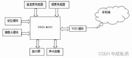
chart 2-1 Overall block diagram of system design
3 System hardware design
3.1 Control system module
This design adopts 32 Bit microcontroller STM32 Series of STM32F103C8T6,....
(1) Excellent energy management
High performance does not mean high energy consumption ......
(2) High performance and innovative chips .....
STM32 The advantage of processor on-chip peripherals comes from dual APB Bus structure , There is a high-speed APB(......
(3) Highly integrated
STM32 The processor maximizes integration , Minimize the impact on external devices ............
(4) Easy to develop
STM32 The processor family is easy to develop , Can quickly bring products to market .
about STM32 Compared with 51 complex .MCU tiny .........
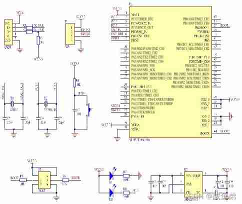
chart 3-1 STM32F103C8T6 Minimum system circuit diagram
This design selection uses LQPF44 Packaged STM32F103C8T6 Main control , As shown in figure, U1, The power supply is 3.3V, Mainly by the power filter circuit .......
The hardware control part of the system is the control core of the kindergarten monitoring system , Mobilize various tasks , The control system first judges the collected data ,.........
3.2 Power module
This design does not require too much power , Use basic USB5V Power supply can be achieved ,........
In order to ensure the normal operation of the kindergarten real-time monitoring system , The power module is required to provide sustainable power supply to the system , Because of the MCU STM32F103C8T6 chip 、WIFI modular 、........
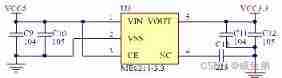
chart 3-2 Voltage stabilizing circuit diagram
3.3 Temperature sensor module
The temperature and humidity sensor module needs to collect the indoor temperature due to the design of the control system , The indoor temperature is relatively dispersed ,DHT11 The sensor can realize multipoint ..........
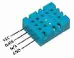
chart 3-3 DHT11 The physical picture of
DHT11 Type a temperature and humidity sensor is connected with single chip microcomputer to realize temperature and humidity collection , Then pass ........
sensor DHT11 Of 1 The pin is connected to the power supply ,2 The pin is the signal input and output pin DATA Connected to MCU ........
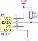
chart 3-4 DHT11 Circuit diagram of
3.4 Smoke sensor module
The application scenario of the smoke sensor module is in the kindergarten classroom , Therefore, smoke sensors need to have high sensitivity 、 Fast response .......
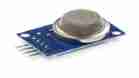
chart 3-5 MQ-2 The physical picture of
Smoke monitoring adopts MQ-2 Smoke sensor ,MQ-2 There are generally two kinds of application circuits for smoke sensors , One is to use comparator circuit for monitoring , The other is to adopt ADC The circuit is tested . This paper uses comparator circuit to monitor , The circuit is shown in the figure 3-6 Shown .

chart 3-6 Smoke signal comparison circuit diagram
MQ-2 Sensors 4 The smoke concentration output by the pin is a DC signal , The output signal is sent to the comparator , When the output voltage is higher than the intermediate threshold voltage , The output of the comparator is 0, The circuit gives an alarm ; conversely , Alarm off ; Can pass .....
This design adopts MQ-2 Integrated modules , There is no need to process the signal of the sensor , Directly through A/D The analog output pin of the converter is ok . Because the working voltage of this module is 5V, The range of analog output voltage is 0-4.5V about ....... The circuit connection diagram is shown in the figure 3-7 Shown .
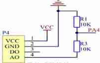
chart 3-7 MQ-2 Sensor circuit connection diagram
By consulting a large number of relevant literature , Combined with national unified standards ,......, As shown in the table 3-1 Shown .
surface 3-1 Threshold table of classroom environmental parameters
Environmental parameters | Threshold settings |
temperature | 18℃~28℃ |
humidity | 30%~80%RH |
smoke | <2000PM |
The system is mainly temperature 、 Control electrical equipment when the smoke is too high ,...... The circuit connection diagram is shown in the figure 3-8 Shown . Circuit and MCU PA0 Connected to a .
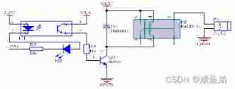
chart 3-8 Connection diagram of control circuit
3.5 Positioning monitoring module
Student position monitoring The selected integrated antenna module is KL400 Reader , There are 8 position 8051 Single chip microcomputer , Include 256B Memory ,16KB Program memory ,3 A timer , Serial data bit 8 position ,......
RFID The module is a monitoring of the position of students on campus , It is installed at the gate of the campus , adopt RFID Reader writer , Enter the student's personal information into the database as a tag , Sew the label on the school uniform , When ...... The connection diagram is shown in the figure 3-9 Shown .
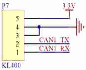
chart 3-9 KL400 modular Circuit connection diagram
3.6 Image acquisition module
The image sensor module adopts photoelectric conversion device , Convert the image of the photosensitive surface into an electronic signal corresponding to the image .......
This kind of sensor can directly convert the electrons in the semiconductor image into voltage signals without complex processing , fast ....... Used in CMOS Of OV7725 camera .
COMS Series of OV7725 Type a camera is used for image acquisition module , Its clock pixel rate can reach 24MHz, This makes it difficult to pass directly through the single chip computer IO Interface captures images , And it takes up a lot of CPU resources ,......
OV7725 yes CMOS The series has 30 Ten thousand resolution camera .....
AL422B It's for FIFO Design video memory , Support simultaneous write and read .
Its data foot D0-D7 With MCU PB8-PB15 Next to each other ...... The circuit connection diagram is shown in the figure 3-10 Shown .
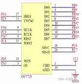
chart 3-10 OV7725 Connection diagram
3.7 Wireless communication module
Wireless communication module adopts WIFI technology ESP8266 chip , Realize the temperature and humidity monitoring in the classroom 、 Smoke detection 、 Upload the student flow status and monitoring , Through and with STM32 The serial communication of is connected to the wireless network ,...... The connection circuit diagram is shown in the figure 3-11 Shown .
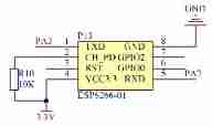
chart 3-11 ESP8266WIFI Module connection circuit diagram
3.8 Display module
The display module adopts OLED Monitor ,OLED It has low power consumption , Small volume , High display accuracy , And its function is powerful , Suitable for small embedded device development . It has low power consumption 、 The display is clear 、 Simple drive and other advantages . It's using OLED screen IIC-4 Pin interface display .
The OLED It has a variety of driving modes , The common ways are SPI and IIC drive , This time, we use IIC How to interface ,IIC Only two data lines are needed to drive the display , The principle of use is simple . The module has 4 One pin ,VCC Connect the power supply 3.3V Power supply ,GND ground wire ,SCL Pick up STM32F103C8T6 Of IICSCL foot PB6,SDA Pick up STM32F103C8T6 Of IICSDA foot PB7. The circuit connection diagram is shown in the figure 3-12 Shown .
chart 3-12 The circuit connection of the display
3.9 Overall circuit diagram of the system
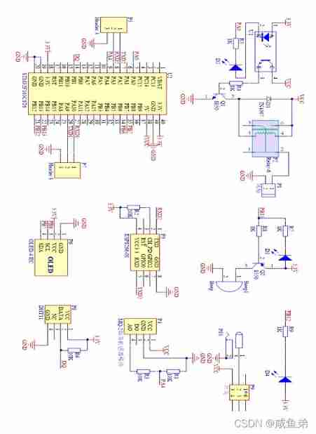
chart 3-13 The overall hardware circuit diagram of the system
4 System software design
4.1 Main program design
In the program development of hardware control system , With Keil5 For the compilation environment , use C Language compiler , And the output HEX file , actually , We use serial debugging assistant and network debugging assistant . Serial debugging assistant and network debugging assistant ,..... The main flow chart is shown in the figure 4-1 As shown in the figure .

chart 4-1 Main program flow chart
4.2 Software design of temperature sensor
It is used in the design DHT11 The temperature and humidity sensor reads the temperature and humidity , Using single chip microcomputer I/O Simulate a certain time sequence to realize the reading of temperature and humidity , The sensor has only one data input and output port , When temperature and humidity are read by single chip microcomputer ,..... Pictured 4-2 Shown DHT11 Work flow chart of temperature and humidity sensor .
chart 4-2 DHT11 Workflow
4.3 Software design of smoke sensor
MQ-2 There is the concentration value output through the analog-to-digital converter and TTL Two output modes of high and low level digital quantity . use STM32 Of ADC Collect flammable gas , And take samples .
When sampling, you need to set the serial port and the corresponding transmission function , And every 1 Seconds to the serial port ...... The work flow chart is shown in Figure 4-3 Shown .
chart 4-3 Smoke concentration collection
4.4 Design of location monitoring software
The position monitoring of students in school is completed by radio frequency identification technology , This module monitors electronic tags and reads personal information ....... Then the terminal sends an abnormal prompt . The subroutine is shown in the figure 4-4 Shown .
chart 4-4 RFID Student supervision flow chart
RFID The reader monitors learners' learning behavior by scanning electronic tags in real time . During the scan , After the reader reads the tag information , Immediately send it to the MCU for processing . The reader uses dual channel mode to process tag information :......
4.5 Image acquisition software design
The acquisition of captured images should be initialized before use , Video shooting OV7725 It should be through SCCB Bus and STM32 Communications , The camera internal register should be configured before use .
OV7725 Chip implementation QVGA Video capture with high resolution ......
When VSYNC Low power level , The image is being transmitted ; stay VSYNC From low level to high level , Indicates that the image has been transmitted .HREF The signal is VSYNC Value from 0 To 1 The use of .HREF Values are determined by 1 change 0 when , Indicates that it has been transmitted ......
The interruption signal of the camera is transmitted to the microprocessor . After the microprocessor receives the interrupt signal ,WEN The level of the pin rises , So you can write FIFO, Then store the complete image data in FIFO in . If the microcontroller receives another ...... The flow chart of image acquisition is shown in Figure 4-7 Shown .
chart 4-5 Flow chart of image acquisition interruption chart 4-6 Flow chart of image acquisition
4.6 WIFI Module software design
The system uses WIFI Wireless module ESP8266 Connect to the server , Therefore, the operation settings of the module must be configured ...... The work flow chart is shown in Figure 4-7 Shown .
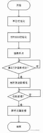
chart 4-7 WIFI Work flow chart
4.7 Connection of mobile phone
The mobile terminal of this design mainly relies on the cloud platform of China Mobile Internet of things , Realize the function of Internet of things . The connection between China Mobile Internet of things platform and MCU mainly includes the following steps .
(1) Registered account 、 Application creation 、 data .....
(2)Esp8266 Of AT Configuration of instructions , The first step is to initialize the serial port ,......
(3) Connect to the platform , Put the product ID、 equipment ID、 Authentication confidence and platform default ......
(4) Data upload , With EDP Of Type Format upload . Function .....
(5) Give orders to .
If the device does not send data or heartbeat packets to the platform within the default time of the platform ,.....
5 System debugging
5.1 Physical test
According to this design , Made the final circuit board , And welded each circuit module . The welding machine shall be operated in sequence , Weld the circuit module first , Rewelded circuit interface and power switch , Disconnect the power supply . Then use a multimeter to check whether each power point is normal , check ...... The final welded object is shown in the figure 5-1 Shown .
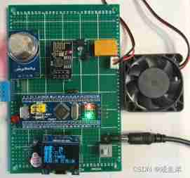
chart 5-1 A physical picture
After the system board starts working normally , wait for 5 About seconds , Green on the minimum system board LED It will light up , Express ESP8266 The module is OK ; On the contrary, it is abnormal .
The operation process is as follows : First of all, turn it on when you ensure that the mobile phone has a network OneNet official APP Device cloud ,......APP The interface is as shown in the figure 5-2 Shown .
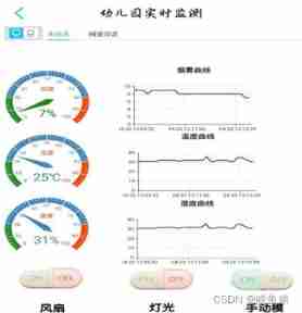
chart 5-2 APP Interface rendering
5.2 test result
(1) Smoke sensor module MQ-2 Test range 300ppm~10000ppm Between , When the device starts up ,......
(2) Temperature and humidity sensor module DHT11 The test scope is 5℃~45℃ Accuracy between 3%,......
(3) When the device starts up , Alarm module when smoke value 、 Either temperature value or humidity value .......
(4) When the device starts up ,WIFI Wireless communication module , stay 100 Rice range , The system is normally connected to the mobile hotspot , screen .......
6 Summary and prospect
6.1 summary
This design is mainly through STM32 Processors and various sensors have built a kindergarten real-time monitoring and control system , The system provides a comfortable classroom environment for children through the design of temperature and humidity sensors , Through the design of smoke sensor to prevent the occurrence of kindergarten fire ......
6.2 expectation
because RFID Radio frequency technology can only monitor the position and condition of children in school , It can't monitor a place where children go to and from school , Later stage can be combined GPS Technology implementation monitoring child positioning . Kindergarten children are too young , It can't express itself well ......
For more detailed documentation , You can download it from the link below .
边栏推荐
- Asynchronous and promise
- Tucson will lose more than $400million in the next year
- 如何搭建一支搞垮公司的技術團隊?
- Data guard -- theoretical explanation (III)
- How to build a technical team that will bring down the company?
- Some query constructors in laravel (2)
- 【附源码】基于知识图谱的智能推荐系统-Sylvie小兔
- Exploration of short text analysis in the field of medical and health (I)
- Unpool(nn.MaxUnpool2d)
- Practice of tdengine in TCL air conditioning energy management platform
猜你喜欢
Bert fine tuning skills experiment
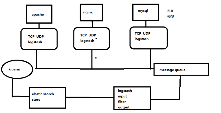
ELK日志分析系统
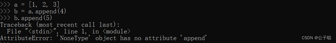
问题解决:AttributeError: ‘NoneType‘ object has no attribute ‘append‘
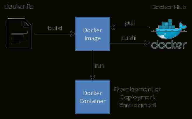
Bumblebee: build, deliver, and run ebpf programs smoothly like silk
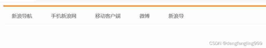
A tab Sina navigation bar
Yolov5 model training and detection
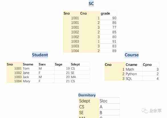
The MySQL team development specifications used by various factories are too detailed. It is recommended to collect them!
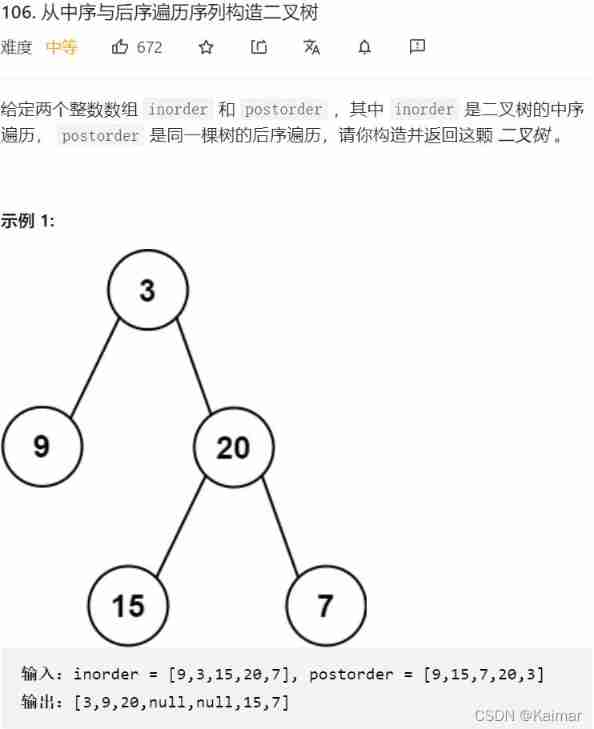
【LeetCode】106. Construct binary tree from middle order and post order traversal sequence (wrong question 2)
Tucson will lose more than $400million in the next year
The application and Optimization Practice of redis in vivo push platform is transferred to the end of metadata by
随机推荐
Talk about the things that must be paid attention to when interviewing programmers
Visual explanation of Newton iteration method
Visual studio 2019 set transparent background (fool teaching)
[download white paper] does your customer relationship management (CRM) really "manage" customers?
Missile interception -- UPC winter vacation training match
Tla+ through examples (XI) -- propositional logic and examples
[understanding of opportunity -38]: Guiguzi - Chapter 5 flying clamp - warning one: there is a kind of killing called "killing"
Which common ports should the server open
Binary tree traversal - middle order traversal (golang)
[source code attached] Intelligent Recommendation System Based on knowledge map -sylvie rabbit
[機緣參悟-38]:鬼穀子-第五飛箝篇 - 警示之一:有一種殺稱為“捧殺”
ASP. Net core 6 framework unveiling example demonstration [01]: initial programming experience
[技术发展-26]:新型信息与通信网络的数据安全
D3js notes
Privatization lightweight continuous integration deployment scheme -- 01 environment configuration (Part 1)
【LeetCode】501. Mode in binary search tree (2 wrong questions)
Icu4c 70 source code download and compilation (win10, vs2022)
[illumination du destin - 38]: Ghost Valley - chapitre 5 Flying clamp - one of the Warnings: There is a kind of killing called "hold Kill"
Stored procedure and stored function in Oracle
Grpc message sending of vertx