当前位置:网站首页>Introduction Guide to stereo vision (1): coordinate system and camera parameters
Introduction Guide to stereo vision (1): coordinate system and camera parameters
2022-07-05 08:54:00 【Li Yingsong~】
Dear students , Our world is 3D The world , Our eyes can observe three-dimensional information , Help us perceive distance , Navigation obstacle avoidance , So as to soar between heaven and earth . Today's world is an intelligent world , Our scientists explore a variety of machine intelligence technologies , Let the machine have the three-dimensional perception of human beings , And hope to surpass human beings in speed and accuracy , For example, positioning navigation in autopilot navigation , Automatic obstacle avoidance of UAV , Three dimensional scanning in the measuring instrument, etc , High intelligent machine intelligence technology is 3D Visual realization .
Stereo vision is an important direction in the field of 3D reconstruction , It simulates the structure of the human eye and simulates the binocular with two cameras , Project in Perspective 、 Based on triangulation , Through the logical complex homonymous point search algorithm , Restore the 3D information in the scene . It is widely used , Autopilot 、 Navigation obstacle avoidance 、 Cultural relic reconstruction 、 Face recognition and many other high-tech applications have its key figure .
This course will help you to understand the theoretical and practical knowledge of stereo vision from simple to profound . We will talk about the coordinate system and camera calibration , From passive stereoscopic to active stereoscopic , Even from deep recovery to grid construction and processing , Interested students , Come and explore the charm of stereovision with me !
This course is an electronic resource , So there will not be too many restrictions in the writing , But it will be logically clear 、 Easy to understand as the goal , Level co., LTD. , If there are deficiencies , Please give me some advice !
Personal wechat :EthanYs6, Add me to the technical exchange group StereoV3D, Talk about technology together .
CSDN Search for :Ethan Li Li Yingsong , see Web based courses .
Lesson code , Upload to github On , Address :StereoV3DCode:https://github.com/ethan-li-coding/StereoV3DCode
List of articles
Pinhole Model Pinhole mode
In scientific research , The internal process of a phenomenon is always complex and difficult to see clearly , And smart scholars always use the simplest model to make the initial description , Propose a relatively simple model . The imaging process is no exception , They use a geometric model to describe the process of mapping coordinate points in the three-dimensional world to the two-dimensional image plane , There are many kinds of this model , The simplest one is called pinhole model .
Everyone has learned the principle of pinhole imaging , In the real world, light from an object passes through a pinhole , It will be projected into an inverted image on the base plate . Pictured 1 Shown :
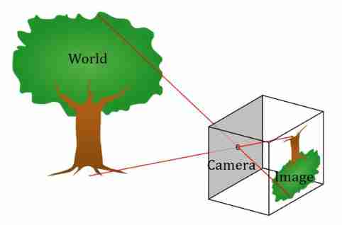
Map the pinhole model to the imaging process , Objects in the real world are imaging targets in three-dimensional space , The pinhole is the center of the camera , The reflection imaging plane is a two-dimensional image plane . As shown in figure 2 ( Left ) Shown , We use simple lines to draw such a relationship , The distance between the center of the camera and the imaging plane is called the focal length f f f. But the imaging of handstand always feels awkward , So switch , Bring the imaging plane to the front of the camera , Keep the focus at f f f, From the imaging process , The image is no longer inverted , Liberated everyone's neck , See the picture 2( Right ) Shown .
 |  |
From the pinhole model , We can find a feature , That's any point in the real world 、 Its projection point on the imaging plane 、 The center of the camera is in a straight line , This feature is called central projection or perspective projection , It is also the basis of imaging analysis . Perspective projection projects three-dimensional space onto a two-dimensional plane , Is a reduced rank space transmission transformation ( Three dimensional space is reduced to two-dimensional space ).
Introduction to coordinate system
Through the pinhole model , We learned about the imaging process , It seems very simple , But it's just a picture at this time , Give you sensory understanding , Based on it, complete complex 3D measurement , We must borrow a series of love hate mathematical formulas , And the foundation of the formula , Is a coordinate system , say concretely , It's a Cartesian coordinate system . If you don't know what the Cartesian coordinate system is , I don't think you will open my blog to see here , So the introduction is skipped .
I think you have mastered a prerequisite knowledge : The three key coordinate systems of stereo vision are Image coordinate system 、 Camera coordinate system 、 World coordinate system . without , Then I'll force this concept on you .
Image coordinate system
The image coordinate system is a two-dimensional coordinate system , Is the coordinate system established in the image , Describe the position of pixels in the image , Divided into pixels ( u , v ) (u,v) (u,v) Coordinate system and ( x , y ) (x,y) (x,y) Coordinate system . In computer vision , ( u , v ) (u,v) (u,v) The coordinate system takes the upper left corner as the origin , u u u Axis and v v v The axes are parallel to the two vertical edges of the image plane ( u u u Axis right , v v v Axis down ), Pictured 3 On the left ; ( x , y ) (x,y) (x,y) The coordinate system is like the main point ( u 0 , v 0 ) (u_0,v_0) (u0,v0) Origin , x x x Axis and y y y The axis is respectively connected with u u u Axis and v v v The axes are parallel and in the same direction , Pictured 3 On the right .
 |  |
above-mentioned Image principal point , Special note , It is the vertical point from the photography center to the imaging plane , It is a very important point .
If we know the conversion relationship between pixels and physical size , That is, the physical size of a pixel , That is, the pixel size is d x ∗ d y dx*dy dx∗dy( x x x The direction dimension is d x dx dx, y y y The direction dimension is d y dy dy), You can convert between the two coordinate systems :
u − u 0 = x / d x v − v 0 = y / d y \begin{aligned} u-u_0&=x / d_x\\ v-v_0&=y / d_y \end{aligned} u−u0v−v0=x/dx=y/dy
To facilitate matrix operations , We will write it in matrix form :
[ u v 1 ] = [ 1 d x 0 u 0 0 1 d y v 0 0 0 1 ] [ x y 1 ] \left[\begin{matrix}u\\v\\1\end{matrix}\right]=\left[\begin{matrix}\frac 1 {d_x}& 0&u_0\\ 0& \frac 1 {d_y}&v_0\\0&0&1\end{matrix}\right]\left[\begin{matrix}x\\y\\1\end{matrix}\right] ⎣⎡uv1⎦⎤=⎣⎡dx1000dy10u0v01⎦⎤⎣⎡xy1⎦⎤
The three-dimensional vector on both sides of the formula is a homogeneous expression , That is, set the third dimension to 1 To represent two-dimensional vectors with three-dimensional vectors , The advantage of this is that the transformation from three-dimensional to two-dimensional can be completed by matrix operation . Why do you want to do this conversion ? Because x y xy xy Close connection between coordinate system and camera coordinate system , Students, look back .
Camera coordinate system
The camera coordinate system is a three-dimensional space coordinate system , Is a very critical coordinate system , It undertakes the important task of establishing the connection between the image coordinate system and the world coordinate system . So when people built the camera coordinate system , A key consideration is how to better connect the image coordinate system with the world coordinate system .
Two three-dimensional coordinate systems ( Camera and the world ) The conversion between can be expressed easily by rotation and Translation , The key point is how to better convert the three-dimensional camera coordinate system and the two-dimensional image coordinate system . The plan is like this : The origin of the camera coordinate system is in the center of the camera , X Y XY XY Axes and images x y xy xy In coordinate system x y xy xy Axis parallel , Z Z Z The axis is perpendicular to and faces the image plane , Z Z Z The intersection of the axis and the image plane is the image x y xy xy Origin of coordinate system ( Image principal point ). Pictured 4 Shown .
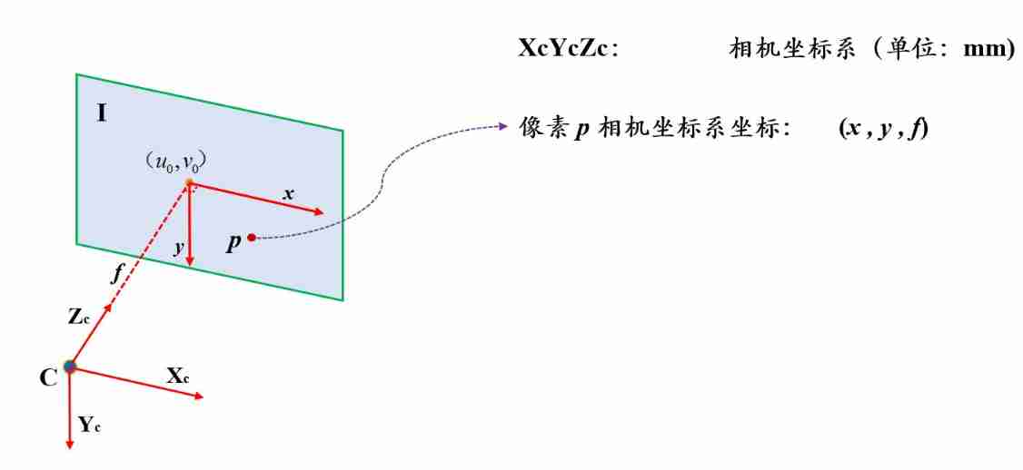
Under this scheme , Like all pixels on the plane in the camera coordinate system Z Z Z The coordinates are equal to the focal length f f f, X Y XY XY Coordinates and images x y xy xy The values in the coordinate system are equal , That is, if pixels p p p In the image x y xy xy The coordinates in the coordinate system are ( x , y ) (x,y) (x,y), Then its coordinate in the camera coordinate system is ( x , y , f ) (x,y,f) (x,y,f).
According to the characteristics of the central projection , Suppose pixels p p p It's a space point P P P The projection point of , So how to establish the coordinate relationship between two brothers ?
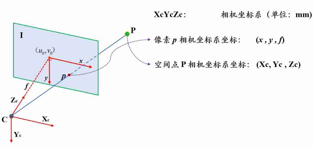
Let's assume pixels p p p The coordinates of the corresponding space point in the camera coordinate system are ( X c , Y c , Z c ) (X_c,Y_c,Z_c) (Xc,Yc,Zc)( Subscript c yes camera It means ). If two points are on the same straight line from the origin of the coordinate system , So what's the relationship between their coordinates ? The answer is proportional . namely
x X c = y Y c = f Z c \frac x {X_c}=\frac y {Y_c}=\frac f {Z_c} Xcx=Ycy=Zcf
To facilitate matrix operations , We will write it in matrix form :
[ x y 1 ] = [ f Z c 0 0 0 f Z c 0 0 0 1 Z c ] [ X c Y c Z c ] \left[\begin{matrix}x\\y\\1\end{matrix}\right]=\left[\begin{matrix}\frac f {Z_c}& 0&0\\ 0& \frac f {Z_c}&0\\0&0&\frac 1 {Z_c}\end{matrix}\right]\left[\begin{matrix}X_c\\Y_c\\Z_c\end{matrix}\right] ⎣⎡xy1⎦⎤=⎣⎢⎡Zcf000Zcf000Zc1⎦⎥⎤⎣⎡XcYcZc⎦⎤
Remember the last section , We put x y xy xy The coordinate system is transformed into u v uv uv Coordinate system , Combine the above formula , You can convert the camera coordinate system into u v uv uv Coordinate system , namely
[ u v 1 ] = [ 1 d x 0 u 0 0 1 d y v 0 0 0 1 ] [ f Z c 0 0 0 f Z c 0 0 0 1 Z c ] [ X c Y c Z c ] = 1 Z c [ f d x 0 u 0 0 f d y v 0 0 0 1 ] [ X c Y c Z c ] \left[\begin{matrix}u\\v\\1\end{matrix}\right]=\left[\begin{matrix}\frac 1 {d_x}& 0&u_0\\ 0& \frac 1 {d_y}&v_0\\0&0&1\end{matrix}\right]\left[\begin{matrix}\frac f {Z_c}& 0&0\\ 0& \frac f {Z_c}&0\\0&0&\frac 1 {Z_c}\end{matrix}\right]\left[\begin{matrix}X_c\\Y_c\\Z_c\end{matrix}\right]=\frac 1 {Z_c}\left[\begin{matrix}\frac f {d_x}& 0&u_0\\ 0& \frac f {d_y}&v_0\\0&0&1\end{matrix}\right]\left[\begin{matrix}X_c\\Y_c\\Z_c\end{matrix}\right] ⎣⎡uv1⎦⎤=⎣⎡dx1000dy10u0v01⎦⎤⎣⎢⎡Zcf000Zcf000Zc1⎦⎥⎤⎣⎡XcYcZc⎦⎤=Zc1⎣⎢⎡dxf000dyf0u0v01⎦⎥⎤⎣⎡XcYcZc⎦⎤
Usually put Z c Z_c Zc Called scale factor λ λ λ, Put in the middle of the 3x3 A matrix is called an internal parameter matrix K K K, Obviously, the internal parameter matrix K K K It describes the camera coordinate system to u v uv uv Transformation relationship of coordinate system . The simple expression is as follows
λ p = K P c \lambda p=KP_c λp=KPc
Internal parameter matrix
Internal parameter matrix K K K Is one of the key parameters of the camera , f d x \frac f{d_x} dxf and f d y \frac f{d_y} dyf It is actually the focal length in physical size f f f The focal length value converted into pixels , remember f x = f d x f_x=\frac f{d_x} fx=dxf, f y = f d y f_y=\frac f{d_y} fy=dyf, f x f_x fx and f y f_y fy Are the pixel unit values of the focal length in the two pixel directions respectively . Finally, the matrix expression of internal parameters is obtained :
K = [ f x 0 u 0 0 f y v 0 0 0 1 ] K=\left[\begin{matrix}f_x&0&u_0\\0&f_y&v_0\\0&0&1\end{matrix}\right] K=⎣⎡fx000fy0u0v01⎦⎤
One additional thing to know is , Due to manufacturing process deviation , Pixels are not absolute rectangles ( chart 6 Left ), But a parallelogram ( chart 6 Right ).
 |  |
At this time, the vertical boundary of pixels and y y y The axis is not parallel but inclined at a certain angle , So in K K K A skew factor is introduced into the matrix s s s( In fact, we can deduce s = f x t a n ( a ) s=f_xtan(a) s=fxtan(a), It's not going to unfold here , If you are interested, you can check the data and deduce it yourself ), here K K K The matrix is expressed as
K = [ f x s u 0 0 f y v 0 0 0 1 ] K=\left[\begin{matrix}f_x&s&u_0\\0&f_y&v_0\\0&0&1\end{matrix}\right] K=⎣⎡fx00sfy0u0v01⎦⎤
Finally, the camera coordinates to u v uv uv The conversion formula of coordinates is :
λ [ u v 1 ] = [ f x s u 0 0 f y v 0 0 0 1 ] [ X c Y c Z c ] \lambda \left[\begin{matrix}u\\v\\1\end{matrix}\right]=\left[\begin{matrix}f_x&s&u_0\\0&f_y&v_0\\0&0&1\end{matrix}\right]\left[\begin{matrix}X_c\\Y_c\\Z_c\end{matrix}\right] λ⎣⎡uv1⎦⎤=⎣⎡fx00sfy0u0v01⎦⎤⎣⎡XcYcZc⎦⎤
World coordinate system
The world coordinate system is a fixed three-dimensional coordinate system , Is an absolute coordinate system , It aims to unify all points in space to express in the same coordinate system , In different application scenarios , The definition of the world coordinate system is different , For example, in Geodesy , Take the horizontal origin as the origin of the world coordinate system ; In camera calibration , Take a corner of the calibration plate as the world coordinate system .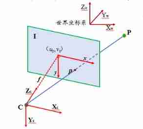
Both the world coordinate system and the camera coordinate system are three-dimensional coordinate systems , They can be transformed by rotation and Translation 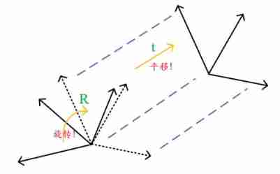
Suppose the space point P The coordinates in the world coordinate system are ( X w , Y w , Z w ) (X_w,Y_w,Z_w) (Xw,Yw,Zw), You can use a 3x3 The unit orthogonal rotation matrix of R R R and 3x1 Translation vector of t t t To convert to camera coordinates ( X c , Y c , Z c ) (X_c,Y_c,Z_c) (Xc,Yc,Zc):
[ X c Y c Z c ] = R 3 × 3 [ X w Y w Z w ] + t 3 × 1 \left[\begin{matrix}X_c\\Y_c\\Z_c\end{matrix}\right]=R_{3\times3}\left[\begin{matrix}X_w\\Y_w\\Z_w\end{matrix}\right]+t_{3\times1} ⎣⎡XcYcZc⎦⎤=R3×3⎣⎡XwYwZw⎦⎤+t3×1
Or write it in another form :
[ X c Y c Z c ] = [ R 3 × 3 t 3 × 1 ] [ X w Y w Z w 1 ] \left[\begin{matrix}X_c\\Y_c\\Z_c\end{matrix}\right]=\left[\begin{matrix}R_{3\times3}&t_{3\times1}\end{matrix}\right] \left[\begin{matrix}X_w\\Y_w\\Z_w\\1\end{matrix}\right] ⎣⎡XcYcZc⎦⎤=[R3×3t3×1]⎣⎢⎢⎡XwYwZw1⎦⎥⎥⎤
Let's put the rotation matrix R R R And the translation vector t t t Called a camera External parameter matrix .
External parameter matrix
The external parameter matrix is also one of the key parameters of the camera , By a 3x3 The unit orthogonal rotation matrix of R R R and 3x1 Translation vector of t t t form , They describe the transformation relationship between the world coordinate system and the camera coordinate system . It should be mentioned that , There are some differences in the definition of the external parameter matrix in different disciplines , For example, in photogrammetry , Transform the camera coordinate system to the rotation matrix of the world coordinate system R R R And the location of the photography center in the world coordinate system C C C As an external parameter . They have the same purpose , It is to describe the conversion relationship between the camera and the world coordinate system .
Similarly, a simple expression is used to describe the transformation from the world coordinate system to the camera coordinate system :
P c = [ R t ] [ P w 1 ] P_c=\left[\begin{matrix}R&t\end{matrix}\right]\left[\begin{matrix}P_w\\1\end{matrix}\right] Pc=[Rt][Pw1]
Projection matrix
Although we spent a lot of time introducing the camera coordinate system , But in practice , The most direct contact is the image u v uv uv Coordinate system and world coordinate system , In 3D image reconstruction , Usually the former is input , The latter is output , So convert the world coordinate system into u v uv uv Coordinate system is a key conversion .
The above has got the world to the camera , Camera to u v uv uv The conversion formula of , So the world to u v uv uv It's not that difficult :
λ [ u v 1 ] = [ f x s u 0 0 f y v 0 0 0 1 ] [ R 3 × 3 t 3 × 1 ] [ X w Y w Z w 1 ] \lambda \left[\begin{matrix}u\\v\\1\end{matrix}\right]=\left[\begin{matrix}f_x&s&u_0\\0&f_y&v_0\\0&0&1\end{matrix}\right]\left[\begin{matrix}R_{3\times3}&t_{3\times1}\end{matrix}\right] \left[\begin{matrix}X_w\\Y_w\\Z_w\\1\end{matrix}\right] λ⎣⎡uv1⎦⎤=⎣⎡fx00sfy0u0v01⎦⎤[R3×3t3×1]⎣⎢⎢⎡XwYwZw1⎦⎥⎥⎤
The transformation from world coordinate system to image coordinate system actually expresses the projection relationship from space point to image point in perspective projection , So the transformation matrix is called projection matrix M M M, Through matrix operation, we can know that the projection matrix is a 3x4 Matrix , It is the product of the internal parameter matrix and the external parameter matrix .
Also use a simple expression to express this transformation :
λ p = K [ R t ] [ P w 1 ] = M [ P w 1 ] , M = K [ R t ] \lambda p=K\left[\begin{matrix}R&t\end{matrix}\right]\left[\begin{matrix}P_w\\1\end{matrix}\right]=M\left[\begin{matrix}P_w\\1\end{matrix}\right],M=K\left[\begin{matrix}R&t\end{matrix}\right] λp=K[Rt][Pw1]=M[Pw1],M=K[Rt]
summary
In this section, we introduce a camera imaging model based on perspective projection through the pinhole model , And the source of all formula derivation : Three coordinate systems ( image / The camera / The world ) Made a detailed introduction , In the process of deeply understanding the coordinate system , Several key camera parameters ( Internal reference / External reference ) Also slowly out . Derivation with diagram and formula , Let everyone grasp this knowledge intuitively and logically , I hope I can give some help to the beginner , I'll see you in the next section .
Practice your homework
Here are some exercises for you , We can deepen our understanding through practice :
practice : Write a Camera class ( be based on Eigen library ), Use the internal parameter matrix K、 Rotation matrix R、 Translation matrix t( Or camera center C) To construct the
Implementation interface :
- Conversion from world coordinate system to camera coordinate system W2C
- Conversion from camera coordinate system to world coordinate system C2W
- Conversion from camera coordinate system to image coordinate system C2I
- Conversion from world coordinate system to image coordinate system W2I
- With depth as a parameter , Conversion from image coordinate system to camera coordinate system I2C
- With depth as a parameter , Transformation from image coordinate system to world coordinate system I2W
Please refer to the address :https://github.com/ethan-li-coding/StereoV3DCode
边栏推荐
- MPSoC QSPI Flash 升级办法
- Programming implementation of ROS learning 6 -service node
- Ros- learn basic knowledge of 0 ROS - nodes, running ROS nodes, topics, services, etc
- Summary of "reversal" problem in challenge Programming Competition
- Halcon shape_ trans
- Codeforces Round #648 (Div. 2) D. Solve The Maze
- 嗨 FUN 一夏,与 StarRocks 一起玩转 SQL Planner!
- Hello everyone, welcome to my CSDN blog!
- 319. Bulb switch
- 696. Count binary substring
猜你喜欢
Solution to the problems of the 17th Zhejiang University City College Program Design Competition (synchronized competition)
![[daiy4] copy of JZ35 complex linked list](/img/bc/ce90bb3cb6f52605255f1d6d6894b0.png)
[daiy4] copy of JZ35 complex linked list
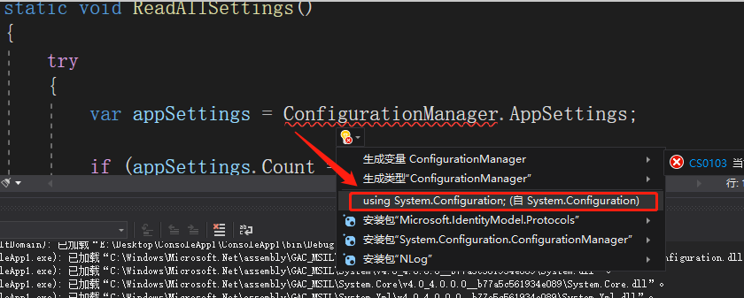
C#【必备技能篇】ConfigurationManager 类的使用(文件App.config的使用)

Wechat H5 official account to get openid climbing account
C [essential skills] use of configurationmanager class (use of file app.config)
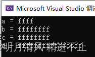
整形的分类:short in long longlong
Halcon blob analysis (ball.hdev)

Add discount recharge and discount shadow ticket plug-ins to the resource realization applet

Guess riddles (7)

Halcon affine transformations to regions
随机推荐
Solution to the problem of the 10th Programming Competition (synchronized competition) of Harbin University of technology "Colin Minglun Cup"
Array,Date,String 对象方法
Blue Bridge Cup provincial match simulation question 9 (MST)
Guess riddles (2)
AdaBoost use
The first week of summer vacation
Numpy pit: after the addition of dimension (n, 1) and dimension (n,) array, the dimension becomes (n, n)
golang 基础 —— golang 向 mysql 插入的时间数据和本地时间不一致
Business modeling of software model | overview
File server migration scheme of a company
12. Dynamic link library, DLL
Redis实现高性能的全文搜索引擎---RediSearch
【日常训练--腾讯精选50】557. 反转字符串中的单词 III
[daily training -- Tencent selected 50] 557 Reverse word III in string
12、动态链接库,dll
The combination of deep learning model and wet experiment is expected to be used for metabolic flux analysis
kubeadm系列-01-preflight究竟有多少check
Golang foundation - the time data inserted by golang into MySQL is inconsistent with the local time
Add discount recharge and discount shadow ticket plug-ins to the resource realization applet
TF coordinate transformation of common components of ros-9 ROS