当前位置:网站首页>Camera calibration (1): basic principles of monocular camera calibration and Zhang Zhengyou calibration
Camera calibration (1): basic principles of monocular camera calibration and Zhang Zhengyou calibration
2022-07-07 11:47:00 【@BangBang】
Why do I need to calibrate the camera
The mathematical meaning of camera :
- The real world is three-dimensional , Taking photos is two-dimensional
- The camera (
As a generalized function): Input 3D scene , The output is a two-dimensional picture ( Gray value ) - The color chart is
RGBThree channels , Each channel can be considered as a gray image function ( The mapping relationship ) It's irreversible, That is to say, we cannot recover the three-dimensional world from two-dimensional photos ( Two dimensional photos have no depth information )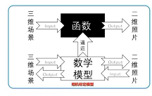
The significance of camera calibration
Camera calibration : Use a pattern Calibration board to solve the process of camera parameters- A simplified mathematical surface model is used to represent the complex three-dimensional to two-dimensional imaging process
- Camera parameters include :
Inside the camera( The focal length )、Camera external parameters( rotate 、 Translation matrix ),Lens distortion parameters purpose : Distortion correction , Binocular vision , Structured light , Three dimensional reconstruction ,SLAM, Camera calibration is required , Only after obtaining the parameters of the camera can it be applied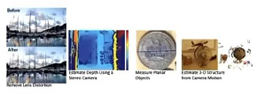
Coordinate system transformation
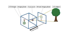
Principle of pinhole imaging
Pinhole imaging instructions
- Simple without lens
- There is a small light source ( candle )
- Real world 3D object , Send light through the aperture ( Pinhole )
- The other side of the camera , Like plane position , Get a real image of handstand
Introduction to coordinate system
Must know terminology :
World coordinate system (World Coords): The position of the point in the real world , Describe the location of the camera , The unit is mCamera coordinate system (Camera Coords):With the camerasensorCenter as origin , Resume camera coordinate system , Company mImage physical coordinate system :The two-dimensional coordinate system obtained after small hole imaging , The unit is mm, The coordinates of new year's day are the points in the graph C C CPixel coordinate system (Pixel Coords): The imaging point is in the camerasensorThe number of rows and columns of the upper pixel , Without any physical unitsPrincipal point: Intersection of optical axis and image plane , The points in the picturep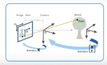
In a binocular or multiocular system , The world coordinate system does not coincide with the camera coordinate system , You need to rotate the world coordinate system through the matrix R Peaceshift matrix T, To the camera coordinate system .
In the above two-dimensional plane , O i O_{i} Oi Is the origin of the image coordinate system , O d O_{d} Od Is the pixel coordinate system , The pixel coordinate system is slightly offset from the origin of the image coordinate system .
(1) World coordinate system to camera coordinate system
spot p Representation in different coordinate systems
- World coordinate system (World Coords): P ( x w , y w , z w ) P(x_{w},y_{w},z_{w}) P(xw,yw,zw)
- Camera coordinate system (World Coords): P ( x c , y c , z c ) P(x_{c},y_{c},z_{c}) P(xc,yc,zc)
The transformation matrix between the world coordinate system and the camera coordinate system :
- R R R: The rotation matrix of the camera coordinate system relative to the world coordinate system
- T T T: The translation matrix of the camera coordinate system relative to the world coordinate system
Mathematical expression of transformation relation :
[ x c y c z c 1 ] = [ R 3 × 3 T 3 × 1 O 1 ] ⋅ [ x w y w z w 1 ] \begin{bmatrix} x_c \\ y_c \\ z_c \\ 1 \\ \end{bmatrix} = \begin{bmatrix} R_{3\times3} & T_{3\times1} \\ O & 1 \\ \end{bmatrix} \cdot \begin{bmatrix} x_w \\ y_w \\ z_w \\ 1 \\ \end{bmatrix} ⎣⎢⎢⎡xcyczc1⎦⎥⎥⎤=[R3×3OT3×11]⋅⎣⎢⎢⎡xwywzw1⎦⎥⎥⎤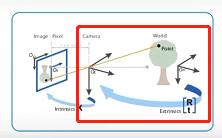
World coordinate system By rotating the matrix R And offset matrix T, Convert to Camera coordinate system , If the world coordinate system coincides with the camera coordinate system , be R It's an identity matrix ,T It's a zero matrix , In this way, the real world point , Convert to a point in the camera coordinate system
(2) Camera coordinate system to image coordinate system
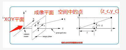
- Suppose the point on the camera p ( x c , y c , z c ) p(x_c,y_c,z_c) p(xc,yc,zc) The imaging point in the image coordinate system is p ′ ( x , y ) p^{'}(x,y) p′(x,y)
- Based on the principle of small hole imaging
- A point in space is imaged in a plane , And X c Y XcY XcY Plane ( The lens ) parallel , From the origin f f f The plane of the
- Take a section Z c Y ZcY ZcY, You can get the right figure , The black dot in the right figure ( z c , y c ) (z_c,y_c) (zc,yc), According to the similar triangle relationship, we can calculate :
y y c = f z c \frac{y}{y_c}=\frac{f}{z_c} ycy=zcf - Take a section X c Y XcY XcY, According to the similar triangle relationship, we can calculate :
x x c = y y c \frac{x}{x_c}=\frac{y}{y_c} xcx=ycy - Combine two triangular transformation relations , Yes :
x x c = y y c = f z c \frac{x}{x_c}=\frac{y}{y_c}=\frac{f}{z_c} xcx=ycy=zcf
After simplification, we can get :
x = f z c ⋅ x c x=\frac{f}{z_c} \cdot x_{c} x=zcf⋅xc
y = f z c ⋅ y c y=\frac{f}{z_c} \cdot y_{c} y=zcf⋅yc
- In matrix form :
z c ⋅ [ x y 1 ] = [ f 0 0 0 0 f 0 0 0 0 1 0 ] ⋅ [ x c y c z c 1 ] z_{c}\cdot \begin{bmatrix} x \\ y \\ 1 \\ \end{bmatrix} = \begin{bmatrix} f &0&0&0 \\ 0 &f&0&0 \\ 0 &0&1&0 \\ \end{bmatrix} \cdot \begin{bmatrix} x_c \\ y_c \\ z_c \\ 1 \\ \end{bmatrix} zc⋅⎣⎡xy1⎦⎤=⎣⎡f000f0001000⎦⎤⋅⎣⎢⎢⎡xcyczc1⎦⎥⎥⎤
(3) Image coordinate system to pixel coordinate system conversion
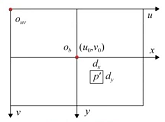
Above picture , Image midpoint O b O_b Ob Represents the origin of the image coordinate system , top left corner O u v O_{uv} Ouv Represents the origin of the pixel coordinate system
Transformation of coordinate system :
- Point of image coordinate system p ′ ( x , y ) p^{'}(x,y) p′(x,y) To the pixel coordinate system ( u , v ) (u,v) (u,v) Transformation
- The origin of the image coordinate system is sensor In the middle of , The unit is mm
- The origin of the pixel coordinate system is sensor Top left corner of , Unit is Pixel, That is, the number of rows and columns of pixels
- The transformation relationship between them :
u = x d x + u 0 , v = y d y + v 0 u=\frac{x}{dx} + u_0 ,v=\frac{y}{dy} + v_0 u=dxx+u0,v=dyy+v0 - In matrix form :
[ u v 1 ] = [ 1 d x 0 u 0 0 1 d y v 0 0 0 1 ] ⋅ [ x y 1 ] \begin{bmatrix} u \\ v \\ 1 \\ \end{bmatrix} = \begin{bmatrix} \frac{1}{dx} &0&u_0 \\ 0 &\frac{1}{dy}&v_0 \\ 0 &0&1 \\ \end{bmatrix} \cdot \begin{bmatrix} x \\ y \\ 1 \\ \end{bmatrix} ⎣⎡uv1⎦⎤=⎣⎡dx1000dy10u0v01⎦⎤⋅⎣⎡xy1⎦⎤- d x d_x dx, d y d_y dy: yes sensor Gu you parameter , Represents the number of millimeters per pixel
- u 0 u_0 u0, v 0 v_0 v0: Represents the origin of the image coordinate system ( Light heart ) The offset from the origin of the pixel coordinate system
Sum up : Conversion formula from camera coordinate system to pixels :
[ u v 1 ] = [ 1 d x 0 u 0 0 1 d y v 0 0 0 1 ] ⋅ 1 z c ⋅ [ f 0 0 0 0 f 0 0 0 0 1 0 ] ⋅ [ x c y c z c 1 ] \begin{bmatrix} u \\ v \\ 1 \\ \end{bmatrix} = \begin{bmatrix} \frac{1}{dx} &0&u_0 \\ 0 &\frac{1}{dy}&v_0 \\ 0 &0&1 \\ \end{bmatrix} \cdot \frac{1}{z_c} \cdot \begin{bmatrix} f &0&0&0 \\ 0 &f&0&0 \\ 0 &0&1&0 \\ \end{bmatrix} \cdot \begin{bmatrix} x_c \\ y_c \\ z_c \\ 1 \\ \end{bmatrix} ⎣⎡uv1⎦⎤=⎣⎡dx1000dy10u0v01⎦⎤⋅zc1⋅⎣⎡f000f0001000⎦⎤⋅⎣⎢⎢⎡xcyczc1⎦⎥⎥⎤
You can get :
u = f x ∗ x c z c + u 0 u=f_x * \frac{x_c}{z_c}+ u_0 u=fx∗zcxc+u0
v = f y ∗ y c z c + v 0 v=f_y * \frac{y_c}{z_c}+ v_0 v=fy∗zcyc+v0
- In the above formula : f x = f d x f_x=\frac{f}{dx} fx=dxf, f y = f d y f_y=\frac{f}{dy} fy=dyf, Focal length divided by the size of a single pixel
- During camera calibration , f , d x , d y f,dx,dy f,dx,dy Cannot be calibrated , f x , f y f_x,f_y fx,fy It can be obtained by calibration
(4) Complete coordinate system conversion
Conversion from world coordinate system to pixel coordinate system
[ u v 1 ] = [ 1 d x 0 u 0 0 1 d y v 0 0 0 1 ] ⋅ [ x y 1 ] \begin{bmatrix} u \\ v \\ 1 \\ \end{bmatrix} = \begin{bmatrix} \frac{1}{dx} &0&u_0 \\ 0 &\frac{1}{dy}&v_0 \\ 0 &0&1 \\ \end{bmatrix} \cdot \begin{bmatrix} x \\ y \\ 1 \\ \end{bmatrix} ⎣⎡uv1⎦⎤=⎣⎡dx1000dy10u0v01⎦⎤⋅⎣⎡xy1⎦⎤- d x d_x dx, d y d_y dy: yes sensor Gu you parameter , Represents the number of millimeters per pixel
- u 0 u_0 u0, v 0 v_0 v0: Represents the origin of the image coordinate system ( Light heart ) The offset from the origin of the pixel coordinate system
Sum up : Conversion formula from camera coordinate system to pixels :
z c ⋅ [ u v 1 ] = [ 1 d x 0 u 0 0 1 d y v 0 0 0 1 ] ⋅ [ f 0 0 0 0 f 0 0 0 0 1 0 ] ⋅ [ R 3 × 3 T 3 × 1 O 1 ] ⋅ [ x w y w z w 1 ] = M 1 M 2 [ x w y w z w 1 ] z_c\cdot\begin{bmatrix} u \\ v \\ 1 \\ \end{bmatrix} = \begin{bmatrix} \frac{1}{dx} &0&u_0 \\ 0 &\frac{1}{dy}&v_0 \\ 0 &0&1 \\ \end{bmatrix} \cdot \begin{bmatrix} f &0&0&0 \\ 0 &f&0&0 \\ 0 &0&1&0 \\ \end{bmatrix} \cdot \begin{bmatrix} R_{3\times3} & T_{3\times1} \\ O & 1 \\ \end{bmatrix} \cdot \begin{bmatrix} x_w \\ y_w \\ z_w \\ 1 \\ \end{bmatrix} = M_1M_2 \begin{bmatrix} x_w \\ y_w \\ z_w \\ 1 \\ \end{bmatrix} zc⋅⎣⎡uv1⎦⎤=⎣⎡dx1000dy10u0v01⎦⎤⋅⎣⎡f000f0001000⎦⎤⋅[R3×3OT3×11]⋅⎣⎢⎢⎡xwywzw1⎦⎥⎥⎤=M1M2⎣⎢⎢⎡xwywzw1⎦⎥⎥⎤
- Inside the camera : The focal length of the camera , Relative offset of pixel coordinates
M 1 = [ f x 0 u 0 0 f y v 0 0 0 1 ] M_1= \begin{bmatrix} f_x &0&u_0 \\ 0 &f_y&v_0 \\ 0 &0&1 \\ \end{bmatrix} M1=⎣⎡fx000fy0u0v01⎦⎤ - Camera external parameters : The conversion relationship between the world coordinate system and the camera coordinate system , The pose matrix of the camera in the world coordinate system
M 2 = [ R 3 × 3 T 3 × 1 ] = [ r 11 r 12 r 13 t 1 r 21 r 22 r 23 t 2 r 31 r 32 r 33 t 3 ] M_2=\begin{bmatrix} R_{3\times3} & T_{3\times1} \\ \end{bmatrix} = \begin{bmatrix} r_{11}&r_{12}&r_{13}&t_{1} \\ r_{21}&r_{22}&r_{23}&t_{2} \\ r_{31}&r_{32}&r_{33}&t_{3} \\ \end{bmatrix} M2=[R3×3T3×1]=⎣⎡r11r21r31r12r22r32r13r23r33t1t2t3⎦⎤
Lens distortion
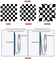
Lens distortion
Ultra wide angle shooting distortion will be more obvious , The more to the edge, the more obvious the distortion
- The error between the actual imaging and the ideal imaging after passing through the lens is the lens distortion
- It is mainly divided into meridional distortion and tangential distortion
Radial distortion - The additive lens shape results in , Along the radial distribution of the lens
- It is divided into barrel distortion and pillow distortion
- The place away from the center of the lens is more curved than the place near the center of the lens
- The distortion at the optical center is 0, The farther away from the optical center, the greater the distortion
- Cheap cameras , Abnormal changes are serious
- Mathematical polynomial description of radial distortion
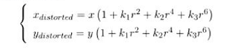
- (x,y) It is a pixel without distortion , ( x d i s t o r t e d , y d i s t o r t e d ) (x_{distorted},y_{distorted}) (xdistorted,ydistorted) Position after distortion
- k 1 , k 2 , k 3 k_1,k_2,k_3 k1,k2,k3: Radial distortion coefficient , The internal reference of the camera , Generally, the first two items are used , Fisheye camera will use the third item
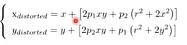
Tangential distortion
- The camera sensor Not parallel to the lens , If the camera is better, there is generally no tangential distortion . Therefore, the influence of radial distortion is generally studied .
- Mathematical representation of distortion :
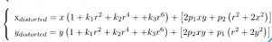
- The two distortions merge :
边栏推荐
- 分布式数据库主从配置(MySQL)
- Swiftui swift internal skill how to perform automatic trigonometric function calculation in swift
- 人大金仓受邀参加《航天七〇六“我与航天电脑有约”全国合作伙伴大会》
- Qt|多个窗口共有一个提示框类
- 总结了200道经典的机器学习面试题(附参考答案)
- R language uses the quantile function to calculate the quantile of the score value (20%, 40%, 60%, 80%), uses the logical operator to encode the corresponding quantile interval (quantile) into the cla
- 本地navicat连接liunx下的oracle报权限不足
- VIM command mode and input mode switching
- Unsupervised learning of visual features by contracting cluster assignments
- Suggestions on one-stop development of testing life
猜你喜欢
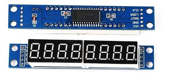
STM32F1与STM32CubeIDE编程实例-MAX7219驱动8位7段数码管(基于SPI)
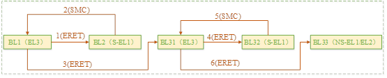
聊聊SOC启动(十) 内核启动先导知识

竟然有一半的人不知道 for 与 foreach 的区别???
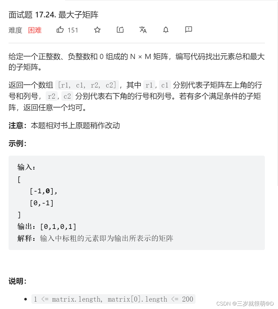
LeetCode - 面试题17.24 最大子矩阵

. Net Maui performance improvement
![[system design] index monitoring and alarm system](/img/8e/9c4c168f7f2b8e1f0786a5fe158544.png)
[system design] index monitoring and alarm system
How much do you know about excel formula?

La voie du succès de la R & D des entreprises Internet à l’échelle des milliers de personnes
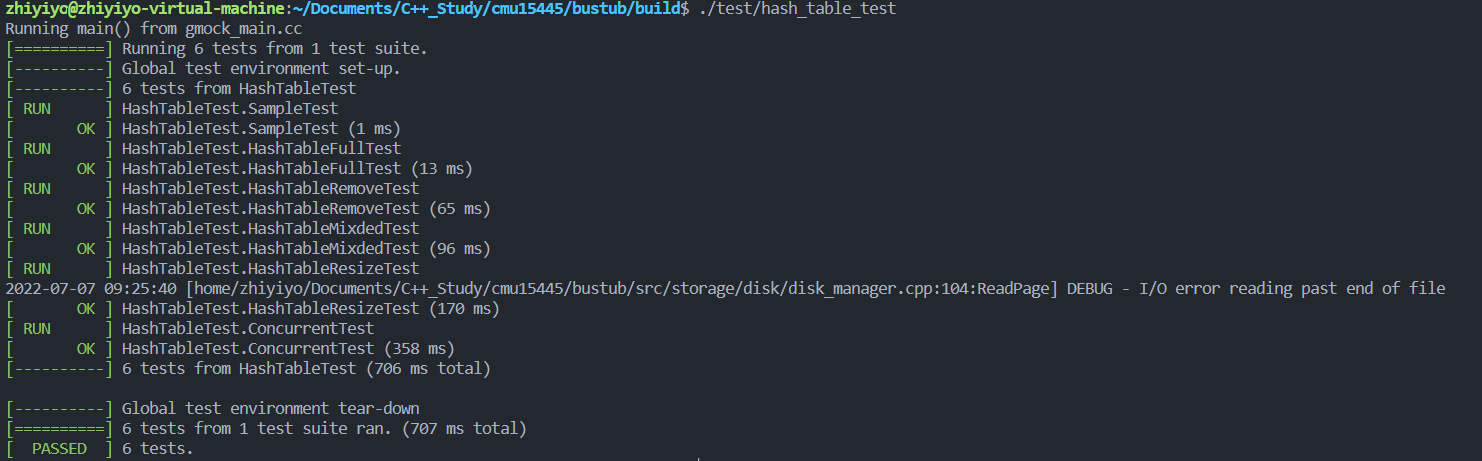
CMU15445 (Fall 2019) 之 Project#2 - Hash Table 详解

Flet教程之 14 ListTile 基础入门(教程含源码)
随机推荐
In depth learning autumn recruitment interview questions collection (1)
R language uses the quantile function to calculate the quantile of the score value (20%, 40%, 60%, 80%), uses the logical operator to encode the corresponding quantile interval (quantile) into the cla
STM32入门开发 采用IIC硬件时序读写AT24C08(EEPROM)
【滤波跟踪】基于matlab扩展卡尔曼滤波EKF和无迹卡尔曼滤波UKF比较【含Matlab源码 1933期】
《论文阅读》Neural Approaches to Conversational AI(1)
R language uses image of magick package_ Mosaic functions and images_ The flatten function stacks multiple pictures together to form a stack layers on top of each other
Electron adding SQLite database
QT implements the delete method of the container
SwiftUI Swift 内功之如何在 Swift 中进行自动三角函数计算
About the application of writing shell script JSON in JMeter
Solve the problem that vscode can only open two tabs
【最短路】Acwing1128信使:floyd最短路
【神经网络】卷积神经网络CNN【含Matlab源码 1932期】
audit 移植
Talk about SOC startup (IX) adding a new board to uboot
深度学习秋招面试题集锦(一)
【紋理特征提取】基於matlab局部二值模式LBP圖像紋理特征提取【含Matlab源碼 1931期】
Software design - "high cohesion and low coupling"
‘module‘ object is not callable错误
Le Cluster kubernets en cours d'exécution veut ajuster l'adresse du segment réseau du pod