当前位置:网站首页>Superscalar processor design yaoyongbin Chapter 9 instruction execution excerpt
Superscalar processor design yaoyongbin Chapter 9 instruction execution excerpt
2022-07-07 11:54:00 【Qi Qi】
9.1 summary
The execution stage is responsible for the execution of instructions , So many things have been done in the previous stage of the assembly line , Is to send instructions to this stage for execution . In the execution phase , The source operand that accepts the instruction , Carry out the specified operation , For example, addition and subtraction 、 Access memory 、 Judgment conditions, etc , Then the result of this execution will be greater than the status of the processor to update , For example, write to the physical register heap , Write to memory , Or get instructions from a specific address , At the same time, the execution result can be used as the source operand of other instructions ( This is the bypass ).
commonly RISC The instruction set includes the following operation types :
(1) Arithmetic operations , For example, addition and subtraction 、 Multiplication and division 、 Logical operation and shift operation ;
(2) Access memory ;
(3) Control the operation of program flow , Including branches 、 Jump 、 Subroutine call 、 Subroutines return equal types ;
(4) Special instructions , Instructions used to implement some special functions , For example, for supporting software processing TLB Missing architecture , Access coprocessor , Memory isolation, etc .
Different types of instructions have different complexity , So in FU The execution time in is also different , This is called different latency, And in modern processors , To achieve greater parallelism , Generally, several will be used at the same time FU Perform parallel operations .
Every FU There are different delay times ,FU The number of determines the maximum number of instructions executed in parallel per cycle , That's what I said earlier issue width.
FU After the operation is completed , It will not use its results to update the status of the processor immediately (Architecture state), For example, it will not immediately write the result to the logical register , Instead, write the results in a temporary place , For example, write to physical register , These states are called speculative States (speculative state), Wait until an instruction leaves the assembly line smoothly , It will really update the status of the processor .
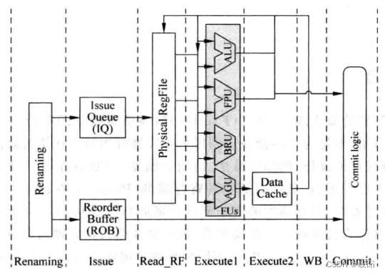
among ,FPU Used to calculate floating-point numbers ;ALU Used for arithmetic and logical operations on integers ;AGU(Address Genneration Unit) Used to calculate the address of access memory , When using virtual storage ,AGU The calculated address is a virtual address , You also need to convert it to a physical address ;BRU(Branch Unit) It is used to calculate the target address of the instructions that control the program flow .
Another important part of the implementation phase is the bypass network bypassing network, It will be complicated FU The result of the operation is immediately sent to the place where it is needed , For example, physical register heap , all FU The input end of the ,Store Buffer secondary . In modern superscalar processors , If you want to execute adjacent related instructions back-to-back , Bypass network is necessary , But as the number of instructions that can be executed in parallel per cycle increases , The bypass network becomes more and more complex , It has become a key part of the processor that restricts the speed improvement .
Suppose we don't consider the bypass network first , Then the operand of the instruction can come from the physical register heap ( Corresponding to non data capture structure ), Or from payload RAM( Corresponding data capture structure ), Then there is still a problem to consider here : Every FU And physical register heap or payload RAM How should each read port of correspond ?
Actually , This is related through the arbitration circuit mentioned before , Every FU All with one 1-of-M The arbitration circuit of is one-to-one correspondence , If an instruction is selected for each arbitration circuit , This instruction will read the physical register heap or payload, So as to get the corresponding operand , Then you can send this instruction to the corresponding FU To perform the .
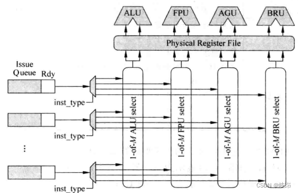
Each of the FU There is one. 1-of-M Arbitration circuit , This arbitration circuit corresponds to the fixed read port of the physical register stack . The total number of read ports required by the physical register stack and issue width Is directly related , If we pursue greater parallelism for processors , You need bigger issue width, This means that the physical register stack needs more read ports , This will restrict the improvement of processor speed , Therefore, modern processors in order to solve this contradiction , Use more cluster structure .
9.2 FU The type of
9.2.1 ALU
It is responsible for the calculation of integer type data , Get the result of integer type , It is generally called ALU. Addition and subtraction of integers , Logic , Shift operation , Even simple multiplication and division , Data transfer instructions , for example mov Instructions and data exchange type instructions , Target address calculation of branch instruction , Address calculation of access memory , It's all going to be here FU Finish in , The specific operation type depends on the design of the processor microarchitecture .
stay ALU After adding multiplication and division operations in , Can make ALU The execution time of is a variable value , For example, it takes a cycle to execute a simple addition and subtraction instruction , And performing multiplication and division requires 32 A cycle , This will bring some trouble to the bypass function .
A typical ALU May be :
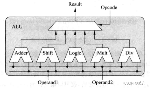
ALU All computing units in receive the operands of the same instruction , So they all calculate , Finally, you need to choose the appropriate result according to the type of this instruction , Because an instruction only needs one computing unit to calculate , But in fact, all the computing units are operated , This will waste part of the power consumption , Registers can be added before each computing unit to lock the operands of the instruction , These operand registers are selectively updated according to the type of instruction , It can save a certain amount of power .
In order to pursue a relatively simple degree of parallelism , High performance processors will choose to use a multiplier alone FU To achieve , And in this FU The function of multiplication and accumulation is supported in , In this way, multiply accumulate type instructions in the instruction set can be executed quickly . Sometimes processors are driven by power and cost considerations , The multiplication function of integer type will be used in floating-point operation FU Finish in . This will definitely lead to a larger number of execution cycles required for multiplication instructions , But considering that this practice will save area , And many applications don't use too many multiplication and division , So I can also accept .
9.2.2 AGU
AGU Used to calculate the address , Instructions for accessing memory types (load/store) They usually carry the memory address they want to use in the instructions ,AGU Be responsible for processing these instructions , Calculate the address carried in the instruction . In fact, in ordinary pipeline processors , It's all in ALU Calculate this address in , But in superscalar processors , Because instructions need to be executed in parallel , And the execution efficiency of accessing memory type instructions directly affects the performance of the processor , So use one alone FU To calculate its address .AGU The calculation process of depends on the instruction set .
If the processor supports virtual addressing , So after AGU The address obtained by the operation is the virtual address , It still needs to go through TLB And other components are converted to physical addresses , Only physical addresses can directly access memory ( In general processors ,L2 Cache And lower level memory are addressed by physical address ), So in processors that support virtual memory ,AGU Only a small part of address translation has been completed , It's just the tip of the iceberg , The real play is to convert virtual addresses to physical addresses , And the process of getting data from the physical address .
9.2.3 BRU
BRU Responsible for handling program control flow control flow Type of instruction , Such as branch instruction branch, Jump instruction jump, Subroutine call and subroutine return instructions . This FU Be responsible for calculating the destination address carried by these instructions , And decide whether to use these customizations according to certain conditions , At the same time FU It also checks whether the branch prediction is correct , Once the branch prediction fails , You need to start the corresponding recovery mechanism . about RISC The processor PC For example , It comes from three sources :
(1) When the sequence is executed ,next_PC = PC + N, N Equal to the word length of each instruction ;
(2) Jump of direct type ,next_PC = PC + offset, offset Is the immediate number carried by the instruction , It specifies... Relative to the current branch instruction PC Value offset , Because this immediate number will not change with the execution of the program , Therefore, the target address of this type of instruction is also relatively easy to predict .
(3) Indirect instructions , The instruction directly specifies the value of a general-purpose register as PC value ,next_PC=GPR[Rs], This type of instruction is also called an absolute type jump . Because with the execution of the program , The value of the general register will change , So the target address of this type of instruction is not easy to predict , If you can directly use direct type jump instructions to achieve the same function , Try not to use this indirect type of jump instruction .
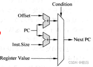
BRU Schematic diagram of operation unit , This FU It mainly completed two parts of work , That is, calculate the target address of the branch instruction , And judge whether the branching condition is true .
Generally speaking , Branch instructions can be divided into two types , One is conditional , One is unconditional .
ARM and PowerPC And other processors use different methods , The condition code is added to the coding of each instruction , Determine whether the instruction is executed according to the value of the condition code . Because every instruction has this condition code , So every instruction can be executed unconditionally , Not limited to branch type instructions , This is equivalent to replacing the control correlation in the program with data correlation .
The advantage of using conditional execution for each instruction is that it can reduce the frequency of branch instructions , In superscalar processors , Just use branch instructions , There may be a risk of wrong prediction , So from this point of view , This implementation of conditional execution can achieve better performance , But it is also a double-edged sword , Because the condition code occupies a part of instruction decoding , As a result, there are fewer parts of the instruction that can actually be allocated to general-purpose registers .
When there are many instructions that require conditional execution , There will be a lot of invalid instructions in the pipeline , In this way, the efficiency is reduced , From these perspectives , Using conditional execution for each instruction reduces performance .
Using conditional execution in superscalar processors , It will cause extra trouble in the process of register renaming . Because the register rename stage cannot get the required condition value , Therefore, the register cannot be renamed selectively , Led to problems .
Superscalar processors implement conditional execution , To solve the problem of register renaming , The simplest way is to stop the pipeline . Wait until the condition of this instruction is calculated , Just rename the instructions behind it , Although no errors will occur , But the efficiency is really not high . Of course , Prediction can also be used to solve this problem , And when the prediction is wrong , The state of the processor needs to be restored , Erase it and subsequent instructions from the pipeline , And put these instructions on RAT Change of , Then fetch these instructions into the pipeline again .
Conditionally executed instructions need to decide whether to execute according to the value of the condition register , for example ARM Each conditionally executed instruction in the processor needs to read the condition register CPSR.
For each item, it needs to be modified CPSR Register instructions ,CPSR Registers are equivalent to a destination register of this instruction . In superscalar processors , We need to get to CPSR Register rename , Subsequent conditional execution instructions will CPSR Register is regarded as a source register . however , because CPSR The width of registers is smaller than that of ordinary general registers , So it is generally CPSR The renaming process of registers uses a separate physical register stack . This is equivalent to adding a destination register and a source register to ordinary instructions , This increases the complexity of register renaming , Resulting in increased power consumption .
Unconditional branch instructions always write the adjustment address to PC in , Used to call subroutines CALL Instructions and subroutines return Return Instructions .
For superscalar processors that implement branch prediction ,BRU The functional unit also has a more important function , It is responsible for checking whether the branch prediction is correct . In the pipeline instruction fetching stage or decoding stage, all branch instructions predicted to jump will be saved to a cache in the order specified in the program , This cache can be called a branch cache branch stack, All branch instructions that predict jumps are stored in the branch cache .
Check the correctness of branch prediction , There will be four results :
(1) A branch instruction is in BRU The result obtained in the functional unit is a jump , And found this branch instruction in the branch cache , The jump address is also the same , Prove that the branch prediction is correct .
(2) A branch instruction is in BRU The result obtained in the functional unit is a jump , And this branch instruction is not found in the branch cache , The jump address is also the same , Prove branch prediction failed .
(3) A branch instruction is in BRU The result obtained in the functional unit is no jump , And this branch instruction is not found in the branch cache , The jump address is also the same , Prove that the branch prediction is correct .
(4) A branch instruction is in BRU The result obtained in the functional unit is no jump , And found this branch instruction in the branch cache , The jump address is also the same , Prove branch prediction failed .
If branch instruction prediction fails , Then you need to start the state recovery process of the processor . If the branch prediction is found to be correct , And all the branch instructions before this branch instruction have been executed correctly , Then you just need to release the resources occupied by this branch instruction and cry .
Another question to consider is whether branch instructions need to be executed out of order ?
There can be multiple branch instructions in the pipeline at the same time , These branch instructions will be predicted , And then put it all together BRU In the transmission queue corresponding to the functional unit , Because branch instructions have the following two main source operands .
(1) Condition register , The branch instruction decides whether to jump according to the value of the condition register , The value of the condition register may not be calculated when the branch instruction enters the transmit queue .
(2) Source operands , For branch instructions that jump directly , The destination address is calculated from PC+offset, among offset It usually exists in the instruction in the form of an immediate number .
All branch instructions entering the transmit queue , It is possible that all the source operands of the branch instruction that enters the pipeline later are ready , Can enter the BRU Function unit for calculation , The branch instruction that enters first may not be ready . In this respect , Using out of order execution of branch instructions can improve some performance , However, the branch instructions that enter the pipeline later heavily depend on the results of the previous branch instructions , If the previous branch instruction finds that its branch prediction fails , These subsequent branch instructions are in BRU The process of being executed in is to do useless work , Waste power .
All in all , If performance comes first , Then you can execute branch instructions in an out of order way , And if we need to consider power consumption , Then executing branch instructions sequentially is a wise choice .
9.2.4 other FU
For example, if the processor supports floating-point operation , Then we need floating-point operation FU; Many processors also support multimedia extensions , Then corresponding FU To deal with it .
9.3 Bypass network
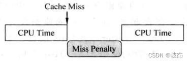
Because the instructions in superscalar processor are executed out of order , And there are branch predictions , So the result of this instruction may not be correct , At this time, the result is called speculative state , An instruction can only leave the assembly line smoothly , Will be allowed to update its results to the processor , At this time, the state of this instruction changes to the correct state (Architecture state), It may have been a long time since this result was calculated , Subsequent instructions cannot wait until this one leaves the pipeline smoothly to use its result .
Only at the execution stage of the pipeline does an instruction really need operands , At the end of the execution phase, you can get its results , So just start from FU Set up a path from the output end to the input end of , It can be FU The results are sent to all FU The input end of the . Of course , This result may also be needed in many places inside the processor , For example, physical register heap 、payload RAM etc. , Therefore, it is necessary to FU The results are also sent to these places , These paths are composed of wires and multiplexers , It is often called a bypass network , It is a superscalar processor that can work in such a deep pipeline , The key technology that can execute adjacent related instructions back-to-back .
In order to reduce the impact of processor cycle time , After the source operand is read from the physical register heap , It still needs a cycle time , To reach FU The input end of the , This cycle is called Source Derive Stage . Empathy ,FU After calculating the result of an instruction , It also needs to go through a complex bypass network to reach all FU The input end of the , Therefore, this stage page is made into a separate assembly line .
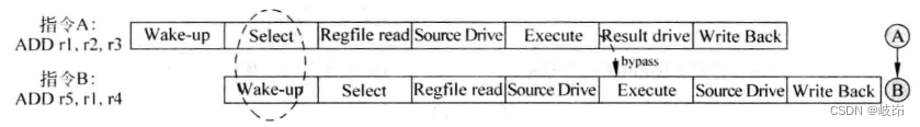
Now you can know , To make two instructions with write read correlation execute back-to-back , There must be two conditions , The instruction wakes up in the cycle selected by the arbitration circuit , There is also bypass network .
Arbitration and wake-up operations in a cycle will seriously restrict the cycle time of the processor , And now the bypass network is introduced , Need to put FU The results are sent to every possible place , In a real processor , Bypass networks require a lot of cabling and multiplexers , It has become a key part of modern processors , It affects the area of the processor 、 Power waste 、 Critical path and physical layout .
stay IBM Of Power In the processor , When two adjacent related instructions are executed , There are bubbles between them bubble, But these bubbles can be replaced by other irrelevant instructions , Because they are all out of order processors , As long as you can find irrelevant instructions , Can alleviate the negative impact of this design on performance .
9.3.1 Simply designed bypass network
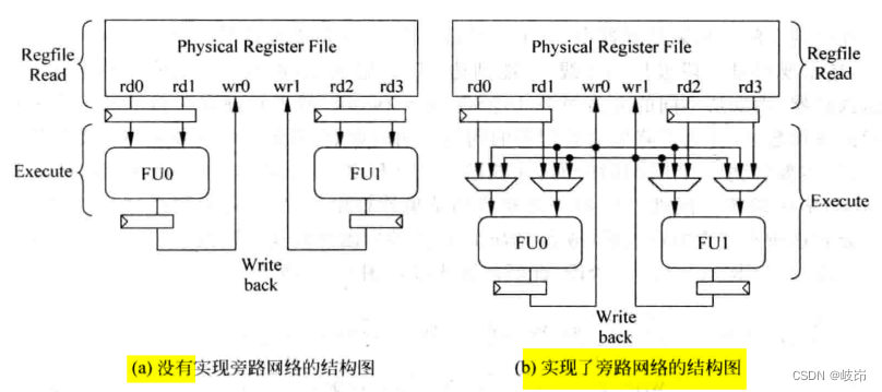
In a bypass network that is not implemented ,FU The operand of comes directly from the physical register file ,FU The result of is also sent directly to the physical register file , One FU To use another FU The calculation result of can only be obtained through the physical register .
In implementing bypass Networks , Every FU The operand of can have three sources , Physical register , Oneself FU Result , other FU Result . meanwhile , Every FU The output processing of is sent out of the physical register heap , It also needs to be sent to all through a bus FU In the multiplexer at the input .
quite a lot FU All have multiple functions , That is, there are multiple computing units . For this FU You need to use a multiplexer , Select appropriate results from different computing units and send them to the bypass network , Such a design becomes bypass sharing. however , When one FU, Different computing units require different cycles , For example, multiplication requires 32 A cycle , Logical operation requires 1 A cycle , At this time, if normal execution is adopted , The same FU The results of the two calculation units in are calculated in the same cycle , All want to pass this FU Corresponding bypass network for transmission , So there's a conflict .
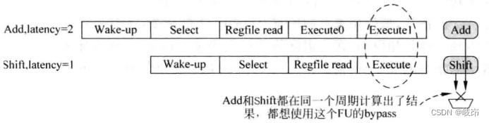
For the conflict of bypass network use , The simplest way is to assume that there will be no conflict .
Suppose an arbitration circuit corresponds to FU Three types of instructions can be computed , In this FU There are three calculation units in , Their latency Namely 1,2 and 3, be :
(1) When this cycle is executed latency=3 Time instruction , It is not allowed to execute in the next cycle latency=2, It is not allowed to execute in the next cycle latency=1 Instructions ;
(2) When this cycle is executed latency=2 Time instruction , It is not allowed to execute in the next cycle latency=1 Instructions ;
(3) When this cycle is executed latency=1 Time instruction , There is no limit to ;
In order to achieve this function , For each arbitration circuit, a control register with a bit width of two bits is set , The high bit is used to intercept all latency=2 Instructions , The low bit is used to intercept all latency=1 Instructions , These two two two bit control registers will be logically shifted to the right every cycle . Corresponding , Two models are added to each table item in the transmission queue , Respectively used to indicate the instructions in it latency yes 1 still 2.
9.3.2 Complex design bypass network
In a more complex assembly line , After the data is read from the physical register , It takes a cycle Source Drive Stage can be reached FU The input end of the , and FU The output results also need to go through a cycle Result Derive To get to the place you need , These changes lead to corresponding changes in the bypass network .
Add a bypass network to the complex pipeline , Make the complexity of the design increase , It has a certain negative impact on the cycle time of the processor .
In the execution phase of the pipeline , Its operands are from the upper pipeline , It can also come from two FU The result of the calculation , They come from the assembly line Result Derive Stage ; And in the assembly line Source Drive Stage , Its operands are from the upper pipeline , It can also come from the results of previous instructions , It can be seen from the previous assembly line diagram , These results are distributed in Result Drive Phase and Write back result . To realize such a bypass network , It requires complex wiring resources and the cooperation of multiplexers to complete .
The process of using a bypass network in a complex pipeline , An instruction from FU Calculate the result , It needs to go through two stages of the assembly line Result Derive and Write Back, Can be written to the general register , In these two cycles , The results of this instruction can be output to the bypass network ; After an instruction reads the general register , Until it really comes FU The first two stages of implementation Source Drive and Execute, Can receive the value sent by the bypass network .
When an instruction is in the pipeline Data Read Stage , When you need to read physical registers , The instruction that generates its operand is now in the pipeline Write back Stage , In this case, bypass network is not required , Because this instruction can read the required operand directly from the physical register ( Suppose the physical register is written in the first half of the cycle , The second half cycle reads ).

When there are more than two instructions separated between two instructions , You no longer need to obtain operands through the bypass grid , Instead, operands can be obtained directly from registers , For two dependent instructions :
(1) When two related instructions are in adjacent cycles , This bypass network can only occur in the pipeline Execute and Result Derive Between the two stages .
(2) When there is a cycle difference between two related instructions , An instruction uses the result of the instruction in the previous cycle before it , Therefore, the bypass network may occur in the pipeline Source Derive and Result Derive Between the two stages , It can also happen in Execute and Write back Between .
(3) When there are two cycles between two related instructions , An instruction uses the result of the previous instruction before it , Therefore, this bypass grid can only occur in Source Derive and Write Back Between .
Two stages are added to the assembly line , At this time, the complexity of the bypass network is already very high , Processing requires a large number of multiplexers , More and longer buses are needed to transmit values that need to be bypassed .
Modern processors all pursue fast speed , High parallelism , That is, we need more FU, Therefore, it is impossible to FU Bypass paths are set between , This will require a lot of cabling resources , Cause serious connection delay .
actually , It doesn't need to be at all FU Bypass networks are set between . for example ,AGU When calculating the address , Generally used ALU Calculated results of , conversely ,ALU Can't use AGU Calculated results of , So in ALU and AGU The bypass network between is unidirectional .
meanwhile load/store unit , Only load The result of the instruction will be used by other instructions ,store Instructions do not have such a need .
Floating point units generally have their own dedicated bypass network , Integer instructions do not directly use floating-point results , So floating point FU To integer FU The bypass network of does not need . As the number of assembly lines increases , The bypass network cannot continue to follow , This is also one reason why we cannot arbitrarily increase the number of pipeline stages .
9.4 Selection of operands
stay FU The input end of the , You need to choose from the output from physical storage or all bypass Networks , find FU The source operand that you really need , This task is accomplished by multiplexers , Since there are so many sources to choose from , The corresponding signal is needed to control the multiplexer , So where does this control signal come from ?
This information of all physical registers can be saved in a table , This form is ScoreBoard, In this table , It records where a physical register passes in its life cycle .
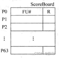
stay ScoreBoard in , For each register , Two contents are recorded :
(1)FU#: From which FU Calculated in , When the value of the physical register needs to be obtained from the bypass network , Need to know which one he comes from FU, In this way, the multiplexer can be controlled to select the corresponding value , When an instruction is selected by the arbitration circuit , If this instruction exists in the destination register , Just put this instruction in which FU The information executed in is written in the above table .
(2)R: Indicates that the value of this physical register has changed from FU Calculated from , And it is written to the physical register file , If subsequent instructions use this physical register , You can directly from PRF Read from , Because you only need to indicate whether this register is PRF in , Just use one bit signal ,0 Indicates that this physical register is no longer PRF in , You need to get this value from the bypass network ,1 Indicates that the PRF Read this value from .
An instruction is in the pipeline Select Stage , Will put it there FU The information executed in is written to SocreBoard The status of the table is FU# in , At the end of the assembly line Write Back Stage , The result of the calculation will be written to the physical register file , At the same time ScoreBoard Also updated , Will read this table , You can get instructions there FU Information executed in , You can also select the appropriate value from the corresponding bypass network .
Because of reading ScoreBoard The process of takes place in the pipeline Execute Stage , This will have a certain negative impact on the cycle time of the processor , When the frequency requirement of the processor is relatively high , This practice may not meet the requirements .
Every FU While broadcasting the calculation result of an instruction , Also broadcast the destination register number of this instruction together .
stay FU Many comparators are added beside the multiplexer at the input , Correspondingly, it will also increase some area and power consumption , But this design structure is simple , No control logic is required , To a certain extent, it can also reduce the complexity of design , Thus reducing the area and power consumption .
With the increase of flow segments that can produce bypass data , The input source of these multiplexers will also be increased , This produces a lot of comparison logic next to each multiplexer , This is also the negative impact of the deep assembly line .
A powerful tool for modern processors to improve the frequency is to reduce the size of the process , At the same time, the improvement of processor performance mainly depends on some prediction algorithms in architecture .
9.5 cluster
Current superscalar design methods lead to more and more complex hardware , For example, physical registers and memory of more ports are required 、 More bypass Networks , These multi port components will increase the area and power consumption of the processor , It seriously restricts the improvement of processor frequency . Therefore, a design concept has emerged -Cluster
Previously in the launch queue , By dividing a unified transmission queue into multiple independent transmission queues , It can reduce the design complexity of arbitration circuit and other components , And speed up . stay FU In the design of , Floating point FU And integer FU The bypass network of , It can greatly reduce the complexity of bypass network, etc .
Cluster Structure extends the above idea , Apply to the physical register heap inside the processor , Launch queue , Bypass network and other components .
9.5.1 Cluster IQ
As the number of instructions that can be executed in parallel per cycle increases , For the centralized transmission queue , It requires more read-write ports and larger capacity , The area and delay will increase , In addition, the transmission queue is already on the critical path inside the processor , Therefore, it is difficult to meet the performance requirements of modern processors by using centralized transmission queues . By dividing it into multiple known distributed transmission queues , Each transmission queue corresponds to one or a few arbitration circuits and FU, In this way, each distributed transmission queue only needs to store the corresponding FU Instructions that can be executed in , Reduce the complexity , such Cluster IQ The advantage is :
(1) It can reduce the number of ports in each distributed transmission queue ;
(2) The arbitration circuit of each distributed transmission queue only needs to choose from a small number of instructions , Therefore, the speed of each blanking circuit can be accelerated .
(3) Because the capacity of distributed transmission queue is relatively small , It will wake up faster .
、 The disadvantage is : In a distributed transmission queue , When the command selected by the arbitration circuit wakes up the queue in other transmission queues , Because it needs to go through a longer main line , So the delay in this part will increase . Across different Cluster The process of wakeup between needs to add a level of pipeline , In this way, when two adjacent instructions with correlation happen to belong to different Cluster when , They can't perform back-to-back , Instead, it introduces a bubble.
For each use cluster The transmission queue of the structure uses a physical register stack . This is equivalent to copying a copy of the physical register heap , For each cluster For internal instructions , Can read operands directly from the physical register heap , Every FU All in their own cluster Bypass network is used inside , The complexity of bypass network is reduced . Of course , Such a design requires the contents of the two physical register files to be consistent , Ask for each FU Updating your Cluster Stack of registers , Another one needs to be updated cluster Register in , Therefore, it seems that , Such a design can reduce the number of read ports of the register heap by half , But the number of write ports in the register heap has not decreased .
By reducing the number of ports in the register heap , Avoid an overly bloated register heap becoming a critical path in the processor .
Physical registers cluster The shortcomings of the design are obvious , In order to reduce the complexity , The bypass network cannot be crossed cluster, When two consecutive instructions with correlation belong to two different cluster when , Subsequent instructions wait until the previous instruction updates the register heap , To read operands from the register heap .
9.5.2 Cluster bypass
To improve the performance of the processor , More instructions can be executed in parallel per cycle , It needs more FU To support , This will lead to a significant increase in the complexity of the bypass network .
Use for bypass Networks cluster structure , Put two FU Distributed in two Cluster in , Every FU You can't send its results to others FU in , It can only be sent to its own bypass network , in other words , The bypass network can only be distributed in each cluster Inside .
When the complexity of bypass network decreases , In the assembly line Source Drive and Result Drive Both flow sections can be removed , This is equivalent to saving two-stage assembly line , Speed up the crossing of different cluster The speed of execution of related instructions . If the relevant instructions belong to different cluster, Then the operands can only be passed through the register heap , When the assembly line is gone Source Drive and Result Drive After the stage , It only needs to be separated by one cycle between two related instructions that belong to different types . It is easy for hardware to find an irrelevant instruction to insert into this cycle to execute , This simplifies the bypass network at the same time , It did not cause a significant decline in performance .
At the same time, the improvement of the main frequency of the processor requires the cycle time to be smaller and smaller , It may cause that the register cannot be as before , Write in the first half cycle , Read in the second half of the cycle , This leads to an increase in the number of cycles between adjacent correlation instructions .
In a sequential processor , Generally, it is not radical to adopt bypass network cluster structure , Instead, try to use a complete bypass network , To reduce the pipeline bubbles introduced by adjacent correlation instructions .
The current story Cluster IQ In the design method of , If two adjacent related instructions belong to two different transmission queues , Then the wake-up process across the transmission queue will introduce a periodic delay , The two related instructions belong to two different cluster FU, Then cross FU The bypass network also needs a period of delay , So take it all together , Will the two delays be superimposed ? The answer is yes !
9.6 Acceleration of memory instructions
9.6.1 memory disambiguation
When talking about the correlation between registers , namely RAW,WAW,WAR, Can be found and solved in the pipeline decoding stage . For memory type instructions , The address of access memory is dynamically calculated during execution , Only after the execution stage of the pipeline , To get the real address to access the memory , for example :
ST R0 #15[R1]
LD R3 #10[R2]
In the decoding stage of the pipeline, it is impossible to know that these two instructions to access memory do not exist RAW The correlation , Only after the execution stage of the assembly line , When the address of this instruction is calculated , Only then can we know .
For instructions that access memory , There is no way to rename these addresses to eliminate WAW and WAR These two correlations .
For instructions that access memory , These three correlations WAW,WAR, RAW All need to be considered , Although theoretically , Instructions accessing memory can also be executed in disorder , But once any of these three correlations is found to be in violation . It needs to be dealt with . This increases the design difficulty to a certain extent , Also in order to maintain the correctness of the memory , In most processors store Instructions are executed sequentially , This can be avoided WAW The correlation ,load Instructions can be implemented in different ways , There are mainly three kinds of :
(1) Complete sequential execution , This is the most conservative method ;
(2) Partially out of order , In sequence store Instructions divide the program into different blocks , Whenever one store After the address of the instruction is calculated , This article store Instructions and subsequent store All between instructions load Instructions can be executed out of order , This way avoid WAR The occurrence of Correlation , At the same time, it can also reduce the impact on RAW The difficulty of correlation detection .
(3) Completely disordered execution ,load Instructions are no longer subject to store Limitations of instructions , as long as load The instructions are ready , You can send it to FU In the implementation of .WAR and RAW These two kinds of correlations need to be processed in the pipeline .
1. Complete sequential execution
because load Instructions are usually at the top of the Correlation , This method cannot make load Instructions are executed as early as possible , As a result, the execution of all relevant instructions is relatively late , Processors using this method , The performance is naturally low , Especially in superscalar processors , Basically, such a conservative design method will not be adopted .
2. Partial disordered execution
although store Instruction is in-order perform , But for two reasons store All between instructions load Instructions can be executed out of order , When one store After the instruction is selected by the arbitration circuit , All behind it load The order is qualified to participate in the arbitration process .
The essence of this method is to be a store After the address carried by the instruction is calculated , After it, enter all of the assembly line load Instructions can be qualified to judge RAW The relevance of , Every one of them load After the instruction calculates the address it carries , Need and front store Compare the carrying address of the instruction . In order to achieve this function , You need a cache to save those that have been selected by the blanking circuit , But they haven't left the assembly line smoothly store Instructions , This cache can be called store buffer.
Even if laod Instructions and store The addresses carried by the instructions are equal , There is no RAW The correlation ,load The data required by the instruction should not come from store Instructions , So this requires a mechanism . When load Instructions and store buffer Of store When comparing addresses with instructions , What do you need to know store Instructions are in front of oneself , Which? store Instructions are behind yourself , about RAW for , Just focus on what's ahead of you store Command can , Therefore, we need to deal with these load/store Mark in sequence before and after the instruction , The sources of tags are as follows :
(a)PC value , But when store When there is a forward jump instruction after the instruction , adopt PC Value can't distinguish the real order .
(b)ROB The number of , stay ROB The sequence of all instructions entering the pipeline is recorded in , So the instruction is ROB The address of can be used to indicate the order between them . however ROB All instructions stored in , Only a part of it is load/store Instructions , If you use this label , It must be very sparse , And these labels should be compared with the size , This causes the comparator to use a larger bit width , Wasted area and power consumption .
(c) In the decoding stage of pipeline , For each load/store The instruction is assigned a number , The width of this number needs to be based on the most supported load/store The number of instructions .
Anyway? , This will partially load Although the method of out of order execution of instructions can improve some performance , But in many cases, it is still not possible to maximize the parallelism between programs .
3. Completely disordered execution
store The instructions are still in-order, however load The instruction will no longer be limited to the store Instructions , as long as laod The operand is ready , It can be submitted to the arbitration circuit according to certain principles , for example oldest-first principle , Choose a suitable load Instructions are sent to FU In the implementation of . In this way , You can make load/store Instructions share a transmit queue , Select only one in each cycle load/store The design of instructions , You can also choose one at the same time in each cycle laod And a store The design of instructions .
You can also make load/store Instructions use separate transmit queues , in other words ,load Instructions use the transmit queue alone ,store Instructions also use a separate transmit queue , such store Instructions can be used simply FIFO structure , There is no need to use age comparison type arbitration circuit .
about RISC For the processor , There are a large number of general registers , So many variables in the program can be directly put into registers , So in the actual procedure ,store/load Between instructions RAW There are not many correlations , and , By executing in advance load Instructions , You can wake up more relevant instructions as soon as possible .
take the reverse into consideration CISC processor , Because there are few registers available , So we often need to deal with memory , Many operands need to be put into memory , such store/load between RAW There are many correlations .
9.6.2 Non blocking Cache
I-Cache Because you only need to read , And taking instructions requires serial order , So his treatment is special , You cannot simply use non blocking methods . Therefore, this section only introduces D-Cache.
In memory , Only instructions to access memory , for example load/store Instructions , To access D-Cache.
(1) about laod The order says , If the required data is not D-Cache in , There is a lack , You need to get data from the next level of physical memory , And in D-Cache According to some algorithm , Find one Cache line To write , If written Cache line yes dirty, You also need to put this line Of data block First write back to physical memory .
(2) about store The order says , If the address it carries is not D-Cache in , So for write back+write allocate Type of Cache Come on , First, you need to find the corresponding address from the physical memory datablock, Read it out , and store Combine the data carried by the instruction , And from D-Cache According to some algorithm , Find one Cache line, Write the merged data to this Cache line in ; If this is replaced Cache line Has been marked as dirty, Then before it is written , You also need to cover this line in data block Write back to physical memory , Only in this way can the merged data be written to this Cache line in .
Whether it's load still store Instructions , Happen when D-Cache miss when ,D-Cache And physical memory need to exchange data , This process usually takes several cycles to complete . If in this cycle , It happened again D-Cache miss, How to deal with ?
The easiest way is to D-Cache Before the missing occurs and is resolved , send D-Cache The data path with physical memory is locked , Only deal with the current missing data , The processor cannot perform other load/store Instructions . Such blocking greatly reduces the parallelism that can be found during program execution . The performance of the processor cannot be improved .
produce D-Cache miss Of laod/store The instruction blocks the following load/store Execution of instructions , So this design method is blocking Cache, During the period of congestion , The processor can only pause execution , Can't do other useful things .
If it's happening D-Cache When it's missing , The processor can continue to execute the following load/store Instructions , This design method is called non blocking Cache, Sometimes called lookup-free Cache, Non blocking Cache Allow the processor to take place D-Cache miss It's time to continue with the new load/store Instructions .
Actually, it's not blocking Cache It is not exclusive to superscalar processors that execute out of order , This method is also available in sequential processors .
face store The order says , Happen when misss when , You need to merge the stored data with this data block , Then write the merged data to D-Cache in .
Drugs support non blocking operation , In the processor, you need to put those that have been generated D-Cache miss Of load/store Save the instructions . utilize Miss Status Holding Register parts , This part consists of two parts :
(a) Missing for the first time : For a given address , visit D-Cache The first deletion is called the first deletion ;
(b) Missing again : Before the first deletion occurs and is not solved , Subsequent instructions to access memory access this missing Cache line, This is called missing again , Two points need to be noted here , First, another loss does not just mean a single loss , In this Cache line Be retrieved to D-Cache Before , Follow up visit this Cache line All of the load/store Instructions will be missing again ; Second, the address missing again may not be the same as the address missing for the first time , As long as they belong to the same Cache line that will do .
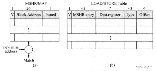
MSHR The main body includes three contents :
(a)V:valid position , Used to indicate whether the current table item is occupied , When the first deletion occurs ,MSHR A table item in the ontology will be occupied , here valid Bits will be marked 1, When needed Cache line When retrieving from the lower level memory , Will release MSHR The table items occupied in the ontology , therefore valid The bit will be cleared .
(b)Block Address: refer to Cache line The public address of the data block in , Suppose the physical address is 32 position , For a size of 64 Byte data block , need 6 Bit address to find a byte of the data block , Therefore, the public address of the data block needs 32-6=26 position . Every time when load/store Command occurs D-Cache miss when , Will be in MSHR Check whether the data block it needs is in the process of being retrieved , It needs a Block Address Only by comparing this item can we know , In this way , All instructions accessing the same data block only need to be processed once , Avoid wasting storage bandwidth .
(c)Issueed: Indicates the first missing load/store Whether the instruction has started processing , That is, whether the process of retrieving data from the next level memory has started , Due to the limited bandwidth of memory , Occupy MSHR The first absence of ontology is not necessarily dealt with immediately , But wait until the conditions are met , Will send a request to read data to the next level memory .
There's one more thing to note , For a missing data , If you access all of this data load/store Instructions are on the path where branch prediction failed , Then even if this data is taken out of the next level memory , Nor should it be written D-Cache in , This will protect you D-Cache Will not be affected by branch prediction failure instructions .
In superscalar processors , Due to disordered execution , It may lead to too many load/store The instruction is on the path where branch prediction failed , This increases D-Cache The probability of missing , As a result, there are more D-Cache Missing needs to be handled .
9.6.3 Keyword first
Occurs when an instruction to access memory is executed D-Cache miss when , The whole data block required by this instruction will be taken out of the next level memory , If prefetching is considered , You also need to take out the next adjacent data block page , Usually, a data block contains more data , for example 64 byte .
If you wait until all the data in the data block is written D-Cache Then send the required data to CPU, This may lead to CPU Wait for a while , To speed up execution , It can be done to D-Cache The next level of memory is transformed , Change the reading order of data .
If the data required by the instruction to access the memory is located in the... Of the data block 6 A word , At this time, the next level memory can be read from 6 Start with two words , When reading to the end of data , And then start from the beginning and put the remaining 0~5 Read out words , The advantage of this is that when the lower level memory returns the first word ,CPU You can get the required data and continue to execute , and D-Cache We will continue to complete the filling of other data , This is equivalent to putting CPU Implementation and Cache The two parts of filling work overlap , It improves the overall execution efficiency , This is keyword Limited Critical Word First. Of course , The lower level memory system needs to add Archie hardware to support this feature , This increases the area and power consumption of silicon chip to a certain extent .
9.6.4 Start early
If you don't pay the cost , Then you can start in advance Early Restart Methods . This method does not change the order in which the memory system reads data .
When the data required by the instruction , That is the first. 6 A word , When taken out from the next level of memory , You can make CPU Resume execution , At this time, the remaining data in the data block can be read , This part of time and CPU The execution time overlaps , So it improves CPU Efficiency of execution .
边栏推荐
- Mastering the new functions of swiftui 4 weatherkit and swift charts
- Test the foundation of development, and teach you to prepare for a fully functional web platform environment
- The road to success in R & D efficiency of 1000 person Internet companies
- Time bomb inside the software: 0-day log4shell is just the tip of the iceberg
- [texture feature extraction] LBP image texture feature extraction based on MATLAB local binary mode [including Matlab source code 1931]
- Electron adding SQLite database
- Fleet tutorial 19 introduction to verticaldivider separator component Foundation (tutorial includes source code)
- 聊聊SOC启动(十一) 内核初始化
- Ask about the version of flinkcdc2.2.0, which supports concurrency. Does this concurrency mean Multiple Parallelism? Now I find that mysqlcdc is full
- 聊聊SOC启动(七) uboot启动流程三
猜你喜欢
总结了200道经典的机器学习面试题(附参考答案)
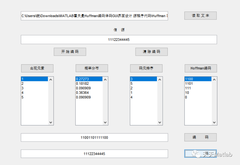
Matlab implementation of Huffman coding and decoding with GUI interface
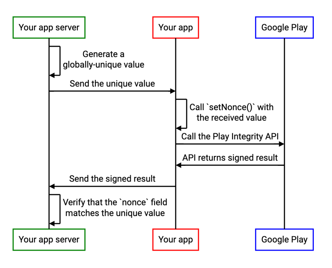
Improve application security through nonce field of play integrity API
Test the foundation of development, and teach you to prepare for a fully functional web platform environment
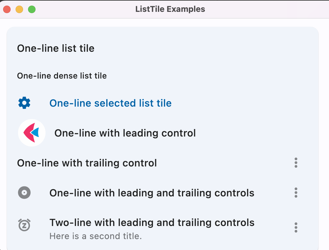
Flet教程之 14 ListTile 基础入门(教程含源码)
Talk about SOC startup (11) kernel initialization

Half of the people don't know the difference between for and foreach???
MATLAB实现Huffman编码译码含GUI界面
Visual Studio 2019 (LocalDB)\MSSQLLocalDB SQL Server 2014 数据库版本为852无法打开,此服务器支持782版及更低版本
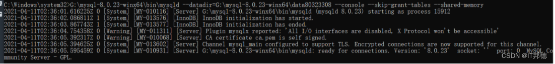
MySQL安装常见报错处理大全
随机推荐
Swiftui tutorial how to realize automatic scrolling function in 2 seconds
Leetcode - interview question 17.24 maximum submatrix
Talk about SOC startup (VII) uboot startup process III
Internet Protocol
[shortest circuit] acwing 1127 Sweet butter (heap optimized dijsktra or SPFA)
Summed up 200 Classic machine learning interview questions (with reference answers)
[filter tracking] strapdown inertial navigation pure inertial navigation solution matlab implementation
浙江大学周亚金:“又破又立”的顶尖安全学者,好奇心驱动的行动派
超标量处理器设计 姚永斌 第10章 指令提交 摘录
Mastering the new functions of swiftui 4 weatherkit and swift charts
Android interview knowledge points
La voie du succès de la R & D des entreprises Internet à l’échelle des milliers de personnes
The road to success in R & D efficiency of 1000 person Internet companies
聊聊SOC启动(九) 为uboot 添加新的board
In SQL, I want to set foreign keys. Why is this problem
Flet教程之 19 VerticalDivider 分隔符组件 基础入门(教程含源码)
sql里,我想设置外键,为什么出现这个问题
STM32F1与STM32CubeIDE编程实例-MAX7219驱动8位7段数码管(基于SPI)
Audit migration
SwiftUI Swift 内功之 Swift 中使用不透明类型的 5 个技巧