当前位置:网站首页>Small guide for rapid formation of manipulator (11): standard nomenclature of coordinate system
Small guide for rapid formation of manipulator (11): standard nomenclature of coordinate system
2022-07-07 20:23:00 【Lie on me】
Directory :
Quick completion guide of mechanical arm ( zero ): Main contents and analysis methods of the guide
Quick completion guide of mechanical arm ( One ): The development of manipulator
Quick completion guide of mechanical arm ( Two ): Application of mechanical arm
Quick completion guide of mechanical arm ( 3、 ... and ): Mechanical structure of mechanical arm
Quick completion guide of mechanical arm ( Four ): Reducer of key components of mechanical arm
Quick completion guide of mechanical arm ( 5、 ... and ): End actuators
Quick completion guide of mechanical arm ( 6、 ... and ): Stepper motor driver
Quick completion guide of mechanical arm ( 7、 ... and ): Description method of robot arm posture
Quick completion guide of mechanical arm ( 8、 ... and ): Kinematic modeling ( standard DH Law )
Quick completion guide of mechanical arm ( Nine ): Forward kinematics analysis
Quick completion guide of mechanical arm ( Ten ): Reachable workspace
Quick completion guide of mechanical arm ( 11、 ... and ): Standard naming of coordinate system
Quick completion guide of mechanical arm ( Twelve ): Inverse kinematics analysis
******************** Here is the main body ********************
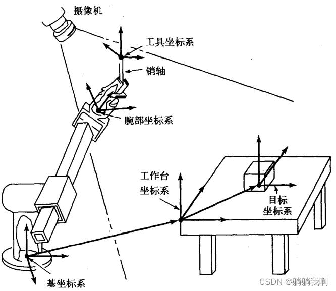
In order to describe the pose relationship between the manipulator and the operating object , We need to give special names to the manipulator and workspace and determine special “ standard ” Coordinate system . The five coordinate systems shown in the following figure are the coordinate systems that need to be named in this chapter . The naming of these five coordinate systems and their subsequent application in the programming and control system of the manipulator provide a kind of universality with the characteristics of simple and easy to understand . The motion of all manipulators will be described according to these coordinate systems .
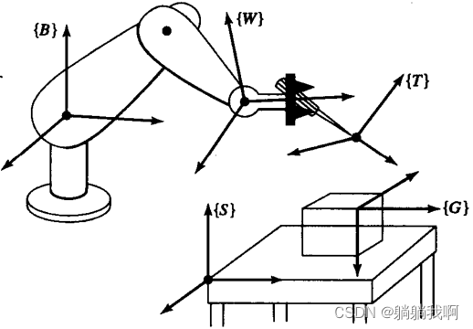
1. Base coordinate system {B}
Base coordinate system {B} Located on the base of the operating arm . It just gives the coordinate system {0} Another name for . Because it is fixedly connected to the static part of the manipulator , So it is sometimes called connecting rod 0.
2. Table coordinate system {S}
Table coordinate system {S} The location of is related to the task . As shown in the figure below , It is located on a corner of the manipulator workbench . For users of the manipulator system , Table coordinate system {S} It is a general coordinate system , All the movements of the manipulator are performed relative to it . Sometimes called task coordinate system 、 World coordinate system or universal coordinate system . The workbench coordinate system is usually determined according to the base coordinate system , namely BT.
3. Target coordinate system {G}
Target coordinate system {G} It is the description of the tool position when the manipulator moves the tool . Especially at the end of the manipulator movement , The tool coordinate system should coincide with the target coordinate system . Target coordinate system {G} It is usually determined according to the workbench coordinate system . In the diagram above , The target coordinate system is located at the shaft hole where the pin shaft is to be inserted . Generally speaking , The motion of all manipulators can be described according to these coordinate systems , They provide a standard for describing the operation of the manipulator .
4. Working coordinate system {T}
Tool coordinate system {T} Attached to the end of the tool held by the mechanical arm . When there is no clamping tool in the hand of the manipulator , Tool coordinate system {T} The origin of is between the fingers of the manipulator . The tool coordinate system is usually determined according to the wrist coordinate system . In the diagram above , The origin of the tool coordinate system is defined at the end of the gripper pin shaft of the manipulator .
5. Wrist coordinate system {W}
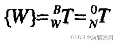
Wrist coordinate system {W} The end link attached to the mechanical arm . The coordinate system fixed on the connecting rod at the end of the manipulator can also be called the coordinate system {N}. In most cases , Wrist coordinate system {W} The origin of is located on the wrist of the manipulator , It moves with the end link of the manipulator . It is defined relative to the base coordinate system , namely
边栏推荐
- You want to kill a port process, but you can't find it in the service list. You can find this process and kill it through the command line to reduce restarting the computer and find the root cause of
- Opencv learning notes high dynamic range (HDR) imaging
- 搞定带WebKitFormBoundary post登录
- Useful win11 tips
- 网络原理(1)——基础原理概述
- [MySQL - Basic] transactions
- TS快速入门-泛型
- 一文读懂数仓中的pg_stat
- 凌云出海记 | 赛盒&华为云:共助跨境电商行业可持续发展
- Micro service remote debug, nocalhost + rainbow micro service development second bullet
猜你喜欢
With st7008, the Bluetooth test is completely grasped
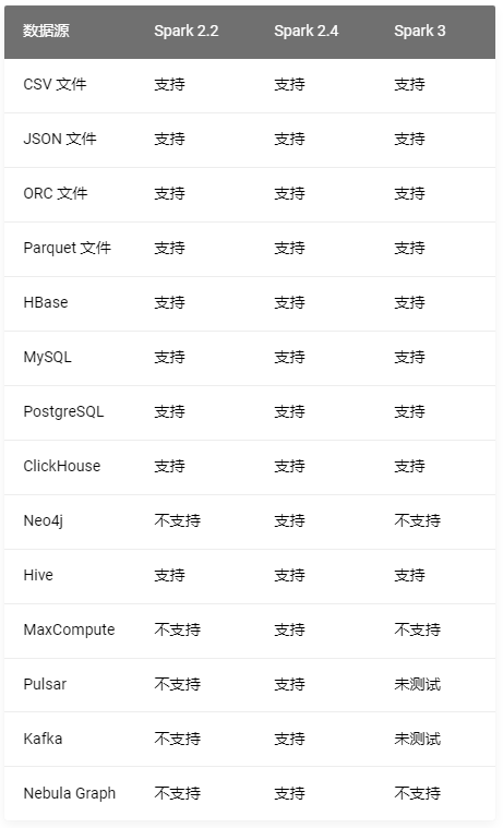
Nebula importer data import practice
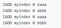
Implement secondary index with Gaussian redis

Chapter 9 Yunji datacanvas company won the highest honor of the "fifth digital finance innovation competition"!
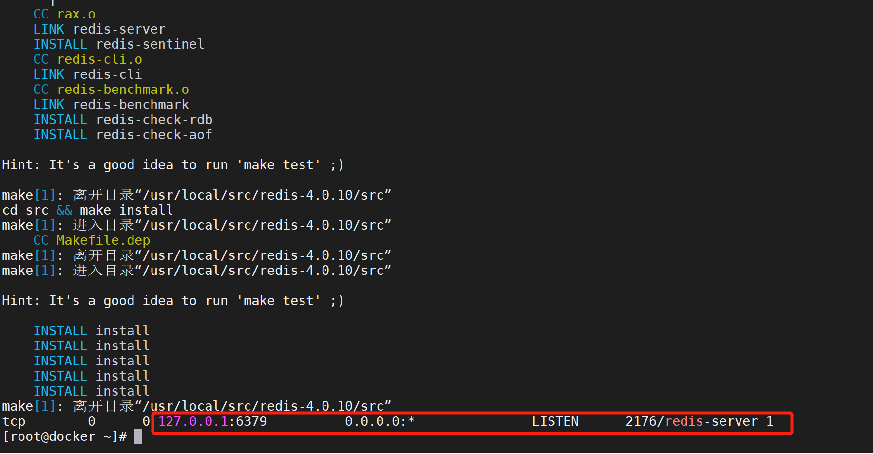
一键部署Redis任意版本

CodeSonar网络研讨会

机械臂速成小指南(十二):逆运动学分析
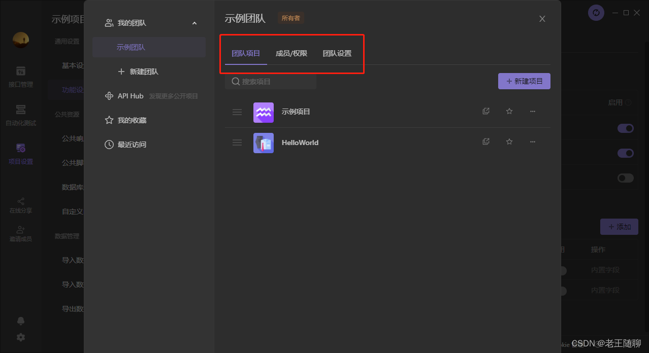
Apifox 接口一体化管理新神器
【mysql篇-基础篇】事务
Data island is the first danger encountered by enterprises in their digital transformation
随机推荐
字符串中数据排序
智能软件分析平台Embold
H3C S7000/S7500E/10500系列堆叠后BFD检测配置方法
论文解读(ValidUtil)《Rethinking the Setting of Semi-supervised Learning on Graphs》
Force buckle 459 Duplicate substring
使用 BR 恢复 Azure Blob Storage 上的备份数据
Force buckle 674 Longest continuous increasing sequence
测量楼的高度
One click deployment of any version of redis
ASP. Net learning & ASP's one word
写了个 Markdown 命令行小工具,希望能提高园友们发文的效率!
[philosophy and practice] the way of program design
Force buckle 599 Minimum index sum of two lists
Vulnhub's funfox2
微服务远程Debug,Nocalhost + Rainbond微服务开发第二弹
Force buckle 88 Merge two ordered arrays
Data island is the first danger encountered by enterprises in their digital transformation
[concept of network principle]
POJ 1742 coins (monotone queue solution) [suggestions collection]
Prometheus remote_write InfluxDB,unable to parse authentication credentials,authorization failed