当前位置:网站首页>[experiment sharing] log in to Cisco devices through the console port
[experiment sharing] log in to Cisco devices through the console port
2022-07-07 23:38:00 【GLAB-Mary】
The experiment purpose
Learn how to login to Cisco The equipment Console mouth
Experimental instructions
Console Port is the most direct configuration Cisco Interface of equipment , Password Recovery , This port must be used for router hang up restore
The experimental steps
1. adopt Console Interface login device
generally speaking , Network devices ( For example, router 、 Switch 、 Firewall, etc ) There will be a dedicated interface for configuration and management on the device panel -Console mouth , Through this interface , And use special cables to connect the equipment and management PC Connect , It can realize the configuration and management of equipment , This is one of the most commonly used equipment configuration and management methods in our project implementation . After the equipment is unpacked and powered on , Usually through the equipment first Console The interface configures the device .
Simply put, there are four steps :
1. Recognize the equipment Console mouth
2. Prepare relevant cables
3. Set up the configuration environment
4. Log in to the device through the terminal management software 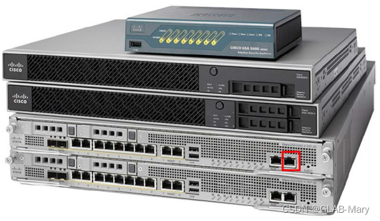
Industrial data communication equipment : Router 、 Switch 、 Firewall, etc , It's usually equipped with Console mouth , Used for equipment configuration and management , The interface will mark Console word , as follows :

The picture above shows a RJ45 Of Console mouth , That is, the crystal head with ordinary network cable Console Line connection interface , Most network devices are RJ45 Of Console Interface .
Now there are also some devices through mini USB Console Interface for connection control .
2. Prepare relevant cables 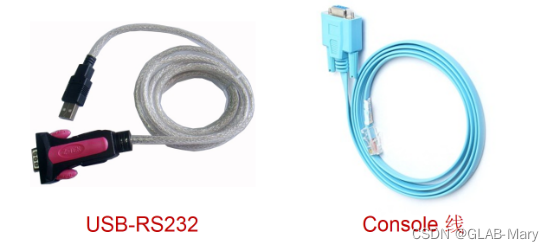
Console Line ( Top right ) Generally, it will be packed with the equipment ( It used to be free , Now? Cisco There's a charge ), One end of the cable is RJ45 Crystal head , The other end is DB9 Serial port connector .RJ45 Connectors are used to connect network devices RJ45 The standard Console mouth , The serial port at the other end of the cable is used to connect PC machine , Early machines were basically equipped with serial ports as standard (COM) Connect , Most of today's machines don't have this interface , So we need another cable ( Above the left ) This is it. USB-RS232 Transfer line . This cable can be said to be one of the necessary equipment for network engineers to travel in the Jianghu , All major electronic cyberports have sales prices ranging from a few to hundreds , A few dozen yuan is almost enough ( You need to install a driver to use ).
3. With these equipment, we can build the experimental topology 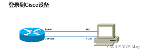
4. Connect the cables according to the following figure , Insert the crystal head into the network device Console mouth
USB End insertion PC Of USB Interface 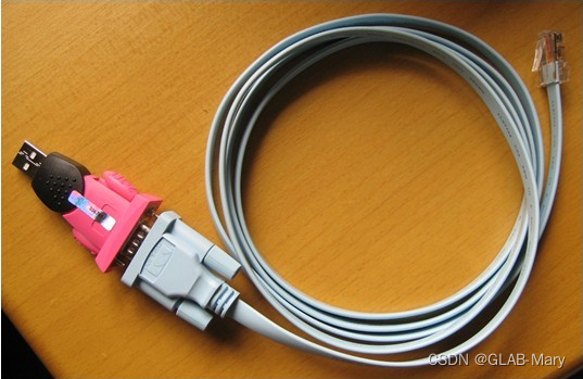
5. open SecureCRT(PUTTY perhaps XP Super terminal win7 It has been eliminated )
Follow the steps below : Click on Quick Connect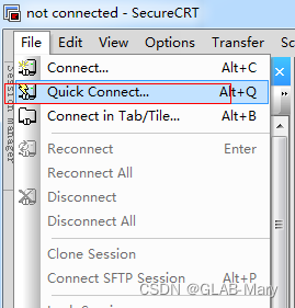
Set relevant parameters according to the following figure :Port Later on , Other parameters are fixed 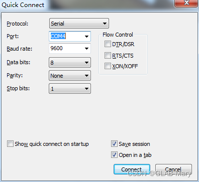
Port You need to open the device manager to check 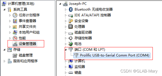
everything OK, Click on Connect Enter the configuration
6. Turn on the router power switch , Observe the router startup process . If the router has been started at this time ,show version Check and fill in the following parameters of the router :
Router model :
Router memory :
IOS Version number :
Type and number of interfaces :
FLASH Capacity :
NVRAM Capacity :
7. example
G-LAB#sh version
Cisco IOS Software, 7200 Software (C7200-ADVSECURITYK9-M), Version 12.4(20)T, RELEASE SOFTWARE (fc3)
Technical Support: http://www.cisco.com/techsupport
Copyright 1986-2008 by Cisco Systems, Inc.
Compiled Fri 11-Jul-08 04:22 by prod_rel_team
ROM: ROMMON Emulation Microcode
BOOTLDR: 7200 Software (C7200-ADVSECURITYK9-M), Version 12.4(20)T, RELEASE SOFTWARE (fc3)
G-LAB uptime is 3 hours, 30 minutes
System returned to ROM by unknown reload cause - suspect boot_data[BOOT_COUNT] 0x0, BOOT_COUNT 0, BOOTDATA 19
System image file is “tftp://255.255.255.255/unknown”
This product contains cryptographic features and is subject to United
States and local country laws governing import, export, transfer and
use. Delivery of Cisco cryptographic products does not imply
third-party authority to import, export, distribute or use encryption.
Importers, exporters, distributors and users are responsible for
compliance with U.S. and local country laws. By using this product you
agree to comply with applicable laws and regulations. If you are unable
to comply with U.S. and local laws, return this product immediately.
A summary of U.S. laws governing Cisco cryptographic products may be found at:
http://www.cisco.com/wwl/export/crypto/tool/stqrg.html
If you require further assistance please contact us by sending email to
Cisco 7206VXR (NPE400) processor (revision A) with 491520K/32768K bytes of memory.
Processor board ID 4294967295
R7000 CPU at 150MHz, Implementation 39, Rev 2.1, 256KB L2 Cache
6 slot VXR midplane, Version 2.1
Last reset from power-on
PCI bus mb0_mb1 (Slots 0, 1, 3 and 5) has a capacity of 600 bandwidth points.
Current configuration on bus mb0_mb1 has a total of 200 bandwidth points.
This configuration is within the PCI bus capacity and is supported.
PCI bus mb2 (Slots 2, 4, 6) has a capacity of 600 bandwidth points.
Current configuration on bus mb2 has a total of 0 bandwidth points
This configuration is within the PCI bus capacity and is supported.
Please refer to the following document "Cisco 7200 Series Port Adaptor
Hardware Configuration Guidelines" on Cisco.com http://www.cisco.com
for c7200 bandwidth points oversubscription and usage guidelines.
1 FastEthernet interface
4 Serial interfaces
125K bytes of NVRAM.
4096K bytes of ATA PCMCIA card at slot 0 (Sector size 512 bytes).
8192K bytes of Flash internal SIMM (Sector size 256K).
Configuration register is 0x2102
8. The experiment is finished
边栏推荐
- Idea automatically generates serialVersionUID
- 伸展树(一) - 图文解析与C语言实现
- Installing gradle
- 包装行业智能供应链S2B2B商城解决方案:开辟电商消费新生态
- Deep understanding of MySQL lock and transaction isolation level
- 2022 certified surveyors are still at a loss when preparing for the exam? Teach you how to take the exam hand in hand?
- MongoDB快速入门
- Sequence of entity layer, Dao layer, service layer and controller layer
- Markdown
- Digital procurement management system for fresh food industry: help fresh food enterprises solve procurement problems and implement online procurement throughout the process
猜你喜欢
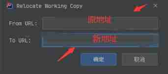
Svn relocation
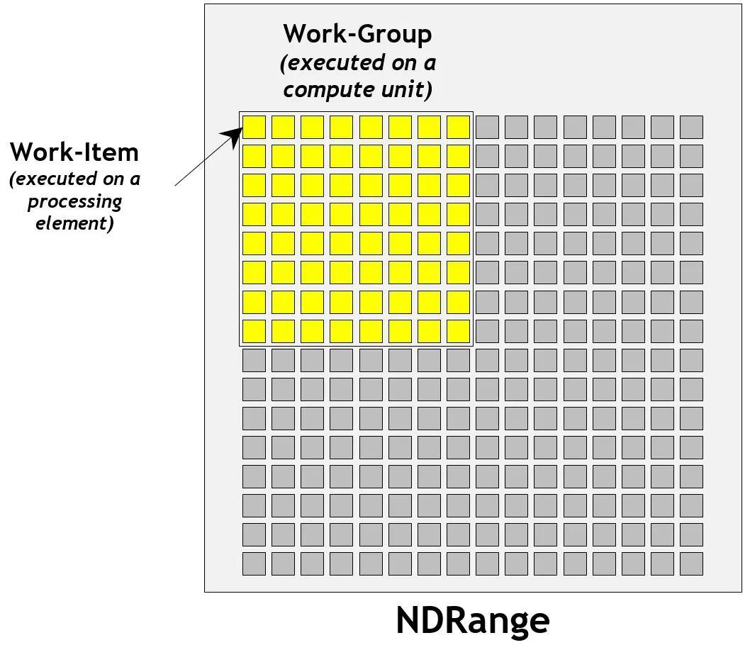
移动端异构运算技术 - GPU OpenCL 编程(基础篇)

B / Qurt Utilisateur Guide (36)
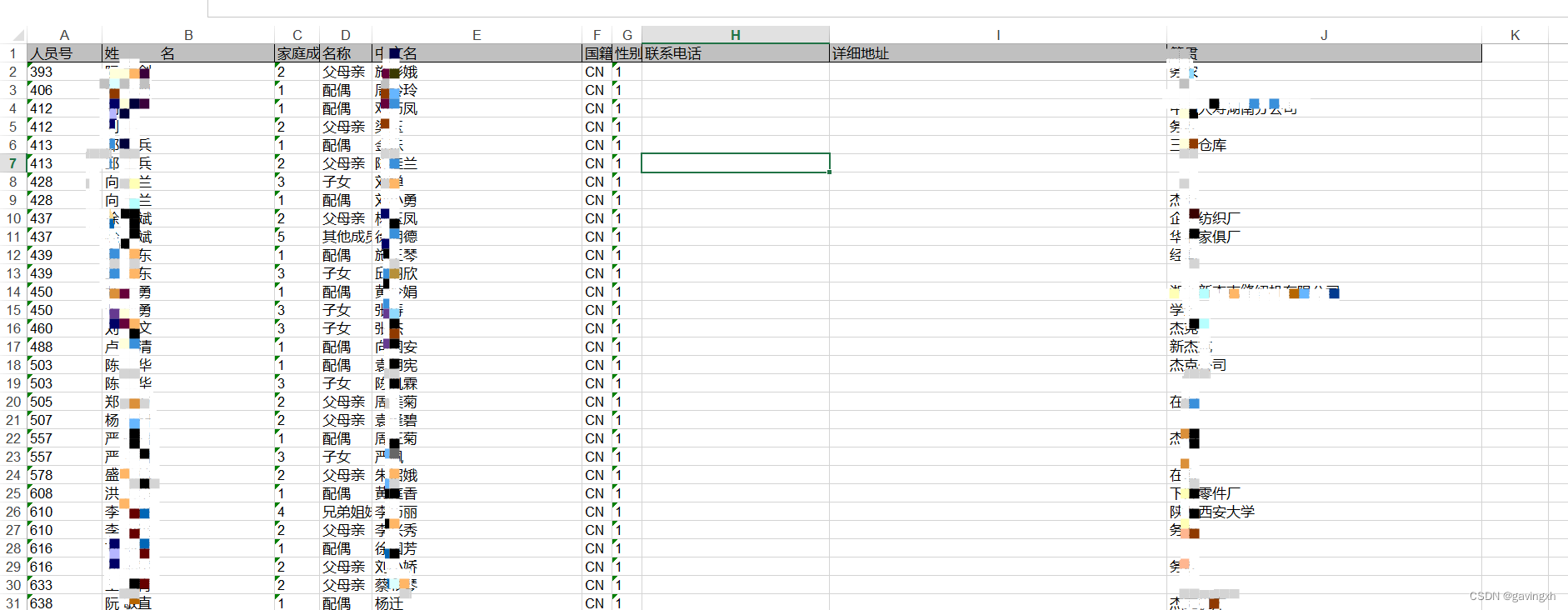
SAP HR family member information

Unity3d Learning Notes 6 - GPU instantiation (1)
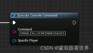
UE4_ Use of ue5 blueprint command node (turn on / off screen response log publish full screen display)

Unity3d learning notes 5 - create sub mesh
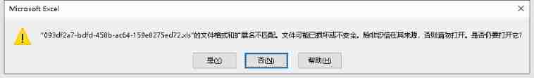
The file format and extension of XLS do not match
![给出一个数组,如 [7864, 284, 347, 7732, 8498],现在需要将数组中的数字拼接起来,返回「最大的可能拼出的数字」](/img/21/2e99dd6173ab4925ec22290cd4a357.png)
给出一个数组,如 [7864, 284, 347, 7732, 8498],现在需要将数组中的数字拼接起来,返回「最大的可能拼出的数字」
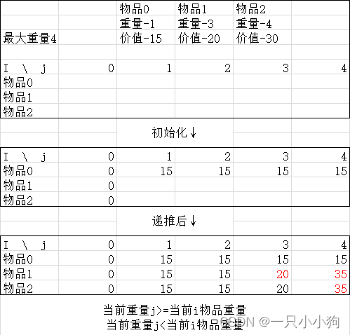
0-1背包问题
随机推荐
The for loop realizes 1-100 addition and eliminates the 4-digit tail number
POJ2392 SpaceElevator [DP]
Summary of SQL single table query 2020.7.27
USB (XV) 2022-04-14
Progress broadcast | all 29 shield machines of Guangzhou Metro Line 7 have been launched
欢聚时代一面
Navicat connects Oracle
Illegal behavior analysis 1
【7.5】15. Sum of three numbers
电子设备行业智能供应链协同平台解决方案:解决低效, 赋能产业数字化升级
Windows set redis to start automatically
Unity3d learning notes 5 - create sub mesh
SAP HR labor contract information 0016
SAP memory parameter tuning process
2022注册测绘师备考开始 还在不知所措?手把手教你怎么考?
B_QuRT_User_Guide(37)
V-for traversal object
移动端异构运算技术 - GPU OpenCL 编程(基础篇)
windows设置redis开启自动启动
C # exchange number, judge to pass the exam