当前位置:网站首页>C # realizes the communication between Modbus protocol and PLC
C # realizes the communication between Modbus protocol and PLC
2022-07-07 22:30:00 【Eva215665】
The project needs to use C# Write an upper computer , use Modbus/TCP Deal with the PLC signal communication , Control the start and stop of servo motor 、 Speed, etc .D:\Code\C#\ConsoleApp1
1. obtain PLC Of IP Address
To be continued ...
2.
“ start-up ” The code for is as follows ,btn_stop_Click yes “ start-up ” The code corresponding to this button , Start a new thread , The actual code is StopEnginer Function
        private void btn_stop_Click(object sender, EventArgs e) // Control the motor to stop
        {

            r_timer.Stop();
            t_timer.Stop();
            Thread t = new Thread(StopEnginer) {
     IsBackground = true };
            t.Start();
        }
private void StopEnginer()
        {

            string cmd_str = "0105081E0000";
            //01 Slave address salve address
            //05 Function code   Write a single coil function WriteSingleCoil( Open source communication library Nmodbus)
            //Nmodbus  Address https://github.com/NModbus/NModbus
            //081E Is to write a single coil address , Refer to delta PLC Application Manual 161 page DVP Device communication address and x Work for excel surface
            //081E = M30 Is the address to control start and stop
            //0000 The last four bits are the values written
            // string cmd_str = (tbx_cmdString.Text).ToUpper();

            ushort[] returnValues = new ushort[30];
            // The string cmd_str Cut into addresses 、 Function code 、 Write address 、 Write the value
            byte address = Convert.ToByte(cmd_str.Substring(0, 2), 16);
            byte Function = Convert.ToByte(cmd_str.Substring(2, 2), 16);
            ushort start = Convert.ToUInt16(cmd_str.Substring(4, 4), 16);
            ushort values = Convert.ToUInt16(cmd_str.Substring(8, 4), 16);
            Console.WriteLine(" This is the call of the fault platform stop process ");
            try
            {

                bool value_TrueOrFalse = Convert.ToUInt16(values) == 0xFF00;

                // call WriteSingleCoil function
                master.WriteSingleCoil(address, start, value_TrueOrFalse);
            }
            catch (Exception ex)
            {

                MessageBox.Show(ex.ToString());
            }
        }
The code is explained as follows , need Modbus agreement 、PLC Knowledge of communication protocols , as well as PLC Address table . For the project PLC The model is delta DELTA DVP series
1. PLC Address table
| name | Corresponding delta DVP series PLC Address |
|---|---|
| Speed setting | D520 |
| Torque setting | D502 |
| Real time speed | D46 |
| Real time torque | D26 |
| Start stop | M30 |
| Torque meter range | D410 |
| Speed range | D414 |
| Loader range | D422 |
| PLC Digital quantity | D418 |
| Speed coefficient | D426 |
| Servo acceleration time | D504 |
| Servo deceleration time | D506 |
| Acceleration and deceleration coefficient | D508 |
among , It controls the start and stop of the motor PLC The address is M30. Delta DVP series PLC in ,S, X, D, M Equal representation PLC device ( Should be the same PLC Related to the internal structure ?? They represent different coil areas ? I'm not sure ), Anyway, I know the address M30 Just OK 了 .
Now check M30 What is the corresponding hexadecimal code address , Because with C to PLC When sending a signal , It needs to be sent in hexadecimal number . The following table is from Delta PLC Application Manual ( as thick as 743 page ) No 161 page , It can be seen that ,M30 stay 000~255 This area , The area is encoded in hexadecimal 08 start , further ,30 The hexadecimal of is 1e, therefore ,PLC Address M30 The hexadecimal address of is 0x081e, among 0x For hexadecimal . Allied ,256~511 The address of this area , Its code is in hexadecimal 09 start ,256~511 They correspond to each other 0x00 ~ 0xFF. for example ,M267, Its hexadecimal address is calculated as :267-256=11,11 The hexadecimal of is 0b, therefore M267 The hexadecimal address of is 0x090b.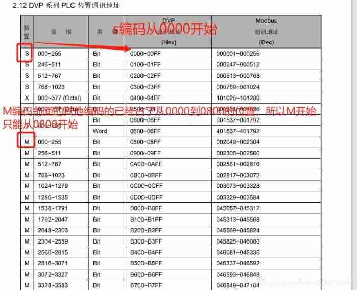
This project PLC The communication with the host computer uses an open source communication library NModbus , Download address https://github.com/NModbus/NModbus.
stay VS2017 in , You can download and install in the following ways :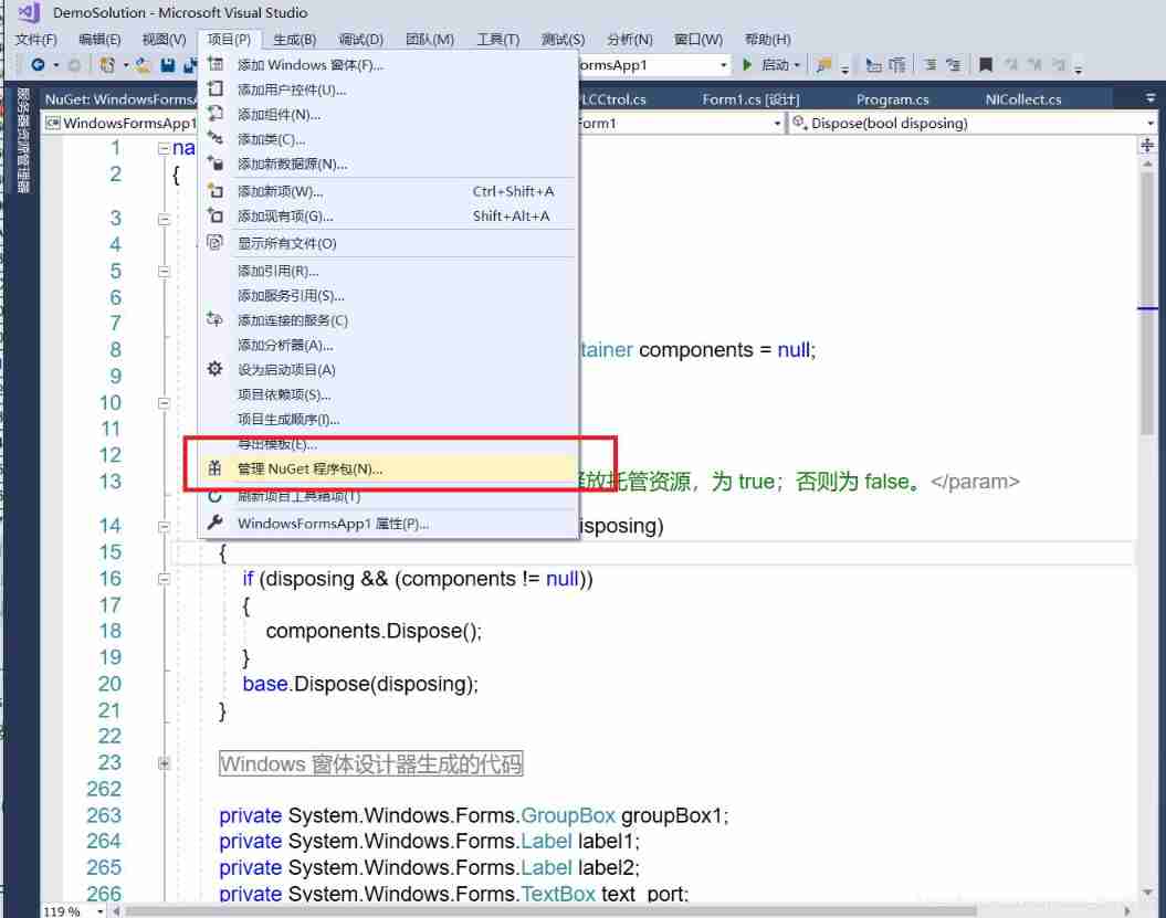
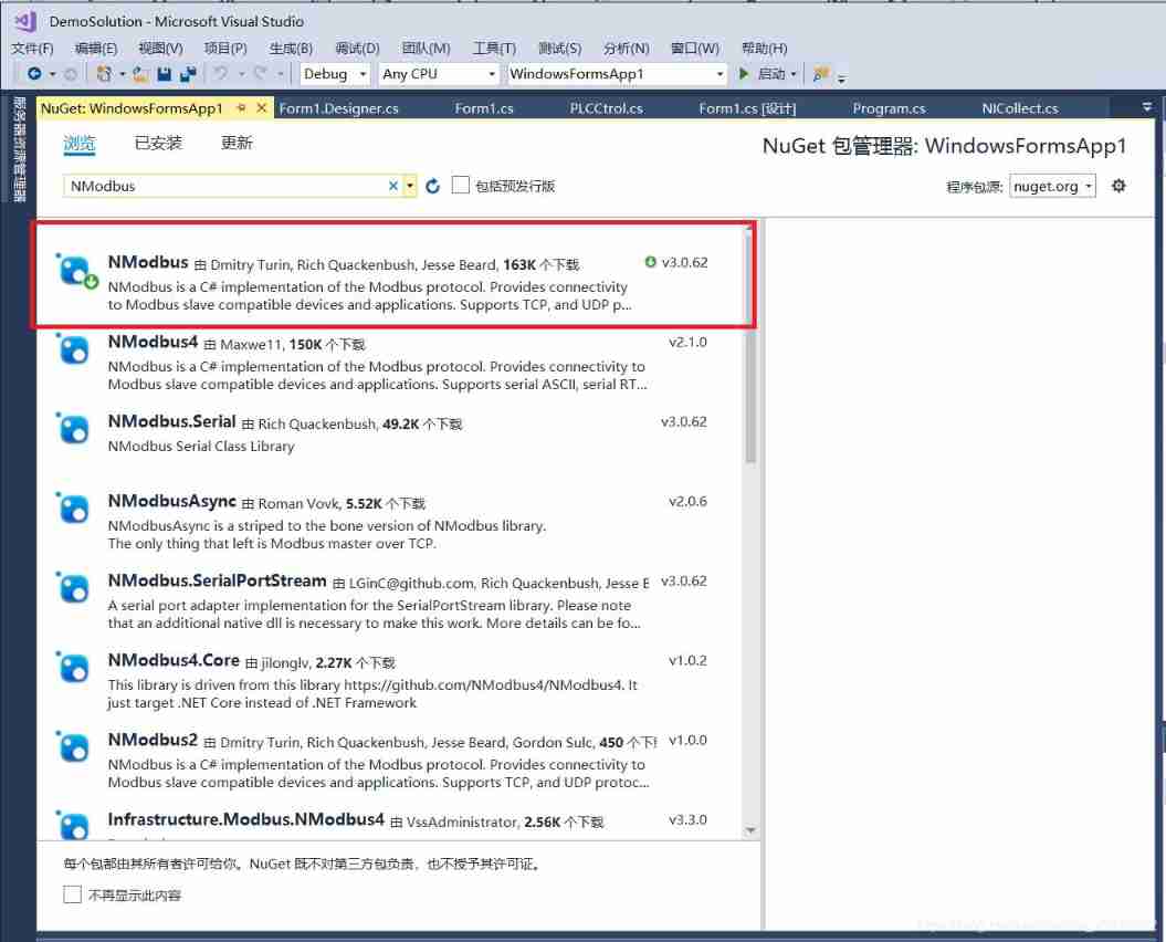
Insert picture description here
After downloading , Define member variables in the corresponding business processing classes
private NModbus.IModbusMaster master;
after , call IModbusMaster Member functions of can communicate , You can see IModbusMaster Some of them are commonly used API Function as follows .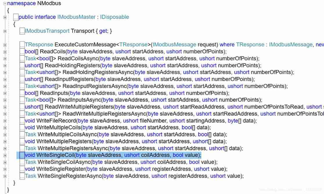
In this case , Will use WriteSingleCoil Function to M30 Write data to the address , Control the start and stop of the motor .WriteSingleCoil The function prototype of is void WriteSingleCoil(byte slaveAddress, ushort coilAddress, bool value);, Three parameters ,slaveAddress,coilAddress It represents the slave station address and coil address respectively , The types are byte and ushort,vlaue It's Boolean , Its value is trueorfalse. to PLC Of M30 The code of the address sending signal starting motor is as follows .
public void start() // to PLC Of M30 Address sends a signal to start the motor
    {

        check();
        byte slaveAddress = 1; // Unit identifier
        ushort coilAddress = 0x81e; // Initial address
        bool value = true;
        master.WriteSingleCoil(slaveAddress, coilAddress, value);
        // void WriteSingleCoil(byte slaveAddress, ushort coilAddress, bool value); The function prototype
    }
2. DELTA DVP series PLC Communication protocol details
Translated from DELTA DVP series PLC Official documents
Communication data framework (Communication Data Frame) as follows :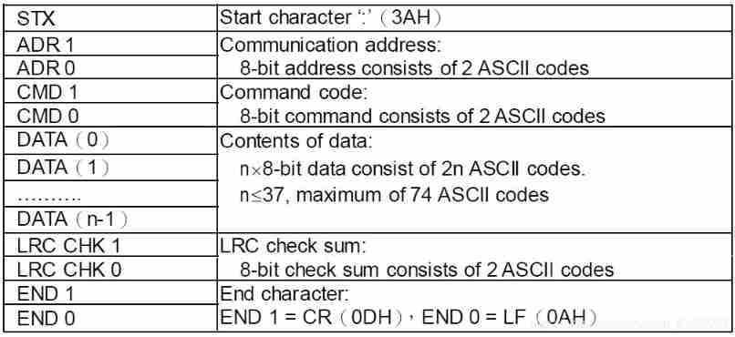
Explain the following :
- STX: Start character , by “:”
- ADR1 and ADR0: mailing address , from 2 individual ASCII Code composition , The valid mailing address range is 0…31.
- CMD1 and CMD0: Command code , from 2 individual ASCII Code composition , To tell PLC What tasks should be performed . This series of PLC The command code of Modbus Some function codes of the Protocol ,Modbus The agreement is shown in the table below . complete Modbus See... For the agreement xxxx. In the table Description yes PLC Corresponding components
| Code | Name | Translation | Function | Description |
|---|---|---|---|---|
| 01 | Read Coil Status | Read coil status | Get the current state of a set of logic coils (on/off) | S, Y, M, T, C |
| 02 | Read Input Status | Read input status | Gets the current state of a set of switch inputs (on/off) | S,X,Y,M,T,C |
| 03 | Read Holding Registers | Read holding register | Gets the current binary value in one or more holding registers | T,C,D |
| 05 | Force Single Coil | Forced single coil | Force the on-off state of a logic coil | S,Y,M,T,C |
| 06 | Preset Signle Register | Preset single register | Load the specific binary into a holder | T,C,D |
| 15 | Force Multiple Coils | Forced multi coil | Force the on / off of a series of continuous logic coils | S,Y,M,T,C |
| 16 | Preset Multiple Register | Preset Multiple Registers | Put the specific binary value into a series of continuous hold | T,C,D |
| 17 | Report Slave ID | None |
- DATA(0)~DATA(n-1): Data content to be sent ,DATA The format of characters depends on the function code . The content of the data includes n individual 8 Bit data , from 2n individual ASCII Code composition ( One 8-bit Data from 2 individual ASCII Code said ),n<=37, therefore DATA Maximum can contain 74 individual ASCII code
Example :Reading Coils T20~T27 from slave device 01, Slave device address 01 Start reading the coil T20-T27 The content in , altogether 8 Bytes (8 words)
PC issue PLC Code for
PC→PLC “:01 03 06 14 00 08 DA CR LF”
The code is parsed as follows :
| Field Name | Example(Hex) |
|---|---|
| Heading | 3A |
| Slave Address | 01 |
| Command code | 03 |
| Starting Address Hi | 06 |
| Starting Address Lo | 14 |
| Number of Points Hi | 00 |
| Number of points Lo | 08 |
| Error Check (LRC) | DA |
| End character 1 | CR |
| End character 2 | LF |
PLC Send to PC Code for :
:01 03 10 00 01 00 02 00 03 00 04 00 05 00 06 00 07 00 08 B8 CR LF
The code is parsed as follows :
| Field Name | Example(Hex) |
|---|---|
| Slave Address | 01 |
| Command code | 03 |
| Bytes Count | 10 |
| Data Hi(T20) | 00 |
| Data Lo (T20) | 01 |
| Data Hi (T21) | 00 |
| Data Lo (T21) | 02 |
| Data Hi (T22) | 00 |
| Data Lo (T22) | 03 |
| Data Hi (T23) | 00 |
| Data Lo (T23) | 04 |
| Data Hi (T24) | 00 |
| Data Lo (T24) | 05 |
| Data Hi (T25) | 00 |
| Data Lo (T25) | 06 |
| Data Hi (T26) | 00 |
| Data Lo (T26) | 07 |
| Data Hi (T27) | 00 |
| Data Lo (T27) | 08 |
| Error Check (LRC) | C8 |
LRC(Longitudinal Redundancy Check) Longitudinal redundancy check ,
DELTA DVP Series of PLC The device address of
边栏推荐
- How to turn on win11 game mode? How to turn on game mode in win11
- 大数据开源项目,一站式全自动化全生命周期运维管家ChengYing(承影)走向何方?
- [azure microservice service fabric] how to transfer seed nodes in the service fabric cluster
- The whole network "chases" Zhong Xuegao
- OpeGL personal notes - lights
- 如何实现横版游戏中角色的移动控制
- Pre sale 179000, hengchi 5 can fire? Product power online depends on how it is sold
- Main functions of OS, Sys and random Standard Libraries
- Remember an experience of using selectmany
- How to quickly check whether the opening area ratio of steel mesh conforms to ipc7525
猜你喜欢
Two methods of calling WCF service by C #
大数据开源项目,一站式全自动化全生命周期运维管家ChengYing(承影)走向何方?
How to judge whether the input content is "number"

Why can't win11 display seconds? How to solve the problem that win11 time does not display seconds?

IP network active evaluation system -- x-vision
Where is the big data open source project, one-stop fully automated full life cycle operation and maintenance steward Chengying (background)?
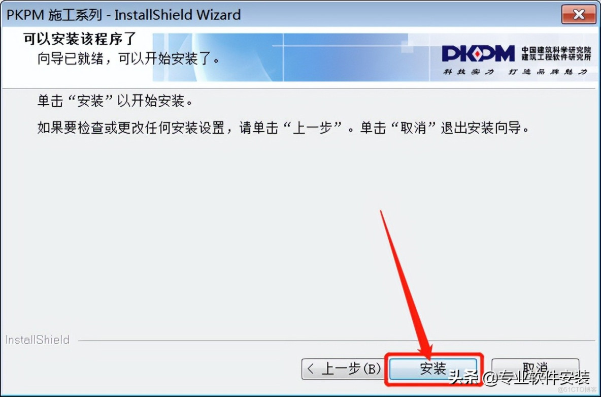
PKPM 2020 software installation package download and installation tutorial
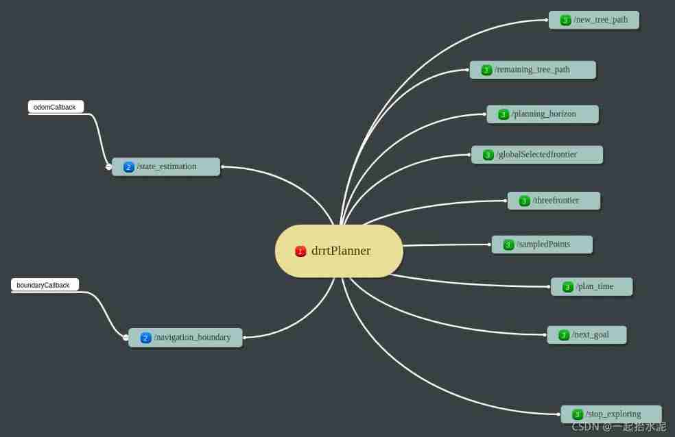
Robot autonomous exploration DSVP: code parsing

Blender exchange group, welcome to the water group ~
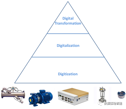
How to make agile digital transformation strategy for manufacturing enterprises
随机推荐
Unity development --- the mouse controls the camera to move, rotate and zoom
双塔模型的最强出装,谷歌又开始玩起“老古董”了?
Revit secondary development - cut view
Aspose. Word operation word document (II)
Aspose. Words merge cells
php 记录完整对接腾讯云直播以及im直播群聊 所遇到的坑
[azure microservice service fabric] the service fabric cluster hangs up because the certificate expires (the upgrade cannot be completed, and the node is unavailable)
Tsconfig of typescript TS basics JSON configuration options
UnicodeDecodeError: ‘gbk‘ codec can‘t decode byte 0xf9 in position 56: illegal multibyte sequence
Welcome to CSDN markdown editor
How does win11 time display the day of the week? How does win11 display the day of the week today?
Add get disabled for RC form
用语雀写文章了,功能真心强大!
Pdf document signature Guide
How to write an augmented matrix into TXT file
npm uninstall和rm直接删除的区别
How to close eslint related rules
苹果在iOS 16中通过'虚拟卡'安全功能进一步进军金融领域
Interview question 01.02 Determine whether it is character rearrangement - auxiliary array algorithm
How to make agile digital transformation strategy for manufacturing enterprises