当前位置:网站首页>Final review notes of single chip microcomputer principle
Final review notes of single chip microcomputer principle
2022-07-07 13:21:00 【10000hours】
explain :
- Reference Content :《 Principle and application of single chip microcomputer ( The third edition )》 Zhang Yigang ; hfut Single chip microcomputer principle course ppt
- Only take notes to back up the blog , Update from time to time
- Some of the pictures are from ppt Screenshot , Apologize for the breach
- The notes of each chapter are divided into text version and mind map version , Mind mapping is derived from text notes , Some chapters have arranged exercises , You can browse the table of contents to find out which chapters have exercises 、
2022/7/5 Repeat the exam :
- The topic is more basic , I have investigated more basic knowledge points
- choice 、 Fill in the blanks 、 Judgment and correction questions are basically an investigation of basic knowledge points , The investigation of memory is basically in this part
- Did not examine the serial port programming problem , Programming problems are also very basic , One is to move data from on-chip to off chip ; One is the output waveform , It's about interrupts and timers
- Then I want to say : Trust your first instinct , The first intuition chose the right answer , When checking the test paper, I put it there for a long time to analyze and reselect the wrong answer , I really appreciate
List of articles
MCS-51 Hardware structure
Note taking mind map
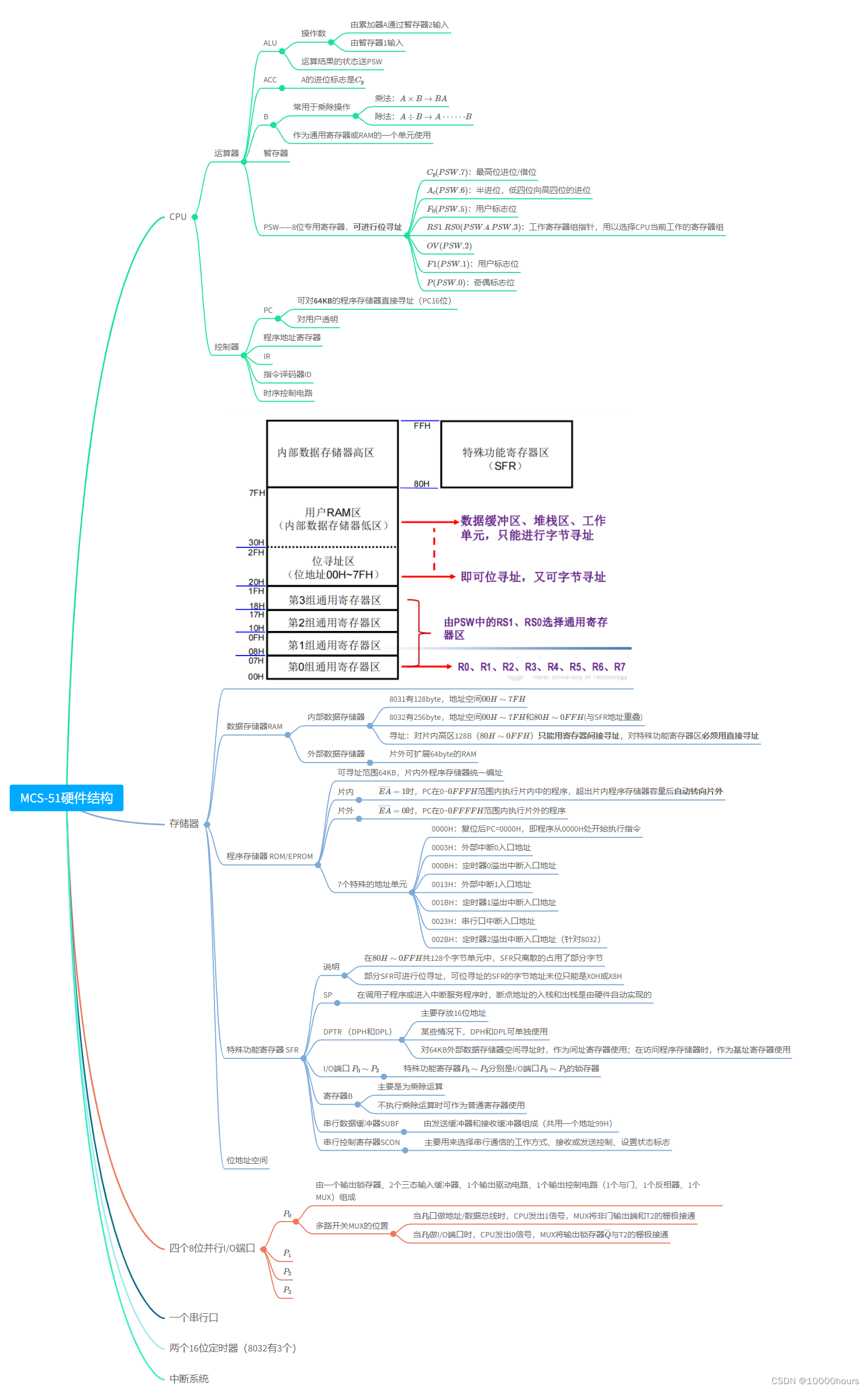
Notes text part
MCS-51 Hardware structure
- CPU
- Arithmetic unit
- ALU
- Operands
- By the accumulator A Through the register 2 Input
- By register 1 Input
- The state of the operation result is sent to PSW
- Operands
- ACC
- A The carry flag of is C y C_y Cy
- B
- Commonly used in multiplication and division
- Multiplication : A × B → B A A\times B \rightarrow BA A×B→BA
- division : A ÷ B → A ⋅ ⋅ ⋅ ⋅ ⋅ ⋅ B A\div B\rightarrow A······ B A÷B→A⋅⋅⋅⋅⋅⋅B
- As a general-purpose register or RAM A unit of uses
- Commonly used in multiplication and division
- Register
- PSW——8 Bit specific register , Bit addressable
- C y ( P S W . 7 ) C_y(PSW.7) Cy(PSW.7): Highest carry / Borrow position
- A c ( P S W . 6 ) A_c(PSW.6) Ac(PSW.6): Half carry , Carry from the lower four bits to the upper four bits
- F 0 ( P S W . 5 ) F_0(PSW.5) F0(PSW.5): User flag bit
- R S 1 R S 0 ( P S W . 4 P S W . 3 ) RS1\ RS0(PSW.4\ PSW.3) RS1 RS0(PSW.4 PSW.3): Working register group pointer , To select CPU Current working register set
- O V ( P S W . 2 ) OV(PSW.2) OV(PSW.2)
- F 1 ( P S W . 1 ) F1(PSW.1) F1(PSW.1): User flag bit
- P ( P S W . 0 ) P(PSW.0) P(PSW.0): Parity flag bit
- ALU
- controller
- PC
- But for 64KB Program memory direct addressing (PC16 position )
- Transparent to users
- Program address register
- IR
- Instruction decoder ID
- Timing control circuit
- PC
- Arithmetic unit
- Memory
![![[Pasted image 20220703095115.png]]](/img/f6/cf8ff647f985a4866f3942f27bc984.png)
Data storage RAM
- Internal data storage
- 8031 Yes 128byte, address space 00 H ∼ 7 F H 00H\sim 7FH 00H∼7FH
- 8032 Yes 256byte, address space 00 H ∼ 7 F H 00H\sim 7FH 00H∼7FH and 80 H ∼ 0 F F H 80H\sim 0FFH 80H∼0FFH( And SFR Address overlap )
- Addressing : For the high area in the film 128B( 80 H ∼ 0 F F H 80H\sim 0FFH 80H∼0FFH) Only registers can be used for indirect addressing , For special function register area Must use direct addressing
- External data storage
- Off chip scalability 64byte Of RAM
- Internal data storage
Program memory ROM/EPROM
- Addressable range 64KB, The on-chip and off-chip program memory is uniformly addressed
- Intraslice
- E A ‾ = 1 \overline{EA}=1 EA=1 when ,PC stay 0~ 0 F F F H 0FFFH 0FFFH Execute the on-chip program within the scope , After exceeding the on-chip program memory capacity Automatic steering wheel outer
- Off slice
- E A ‾ = 0 \overline{EA}=0 EA=0 when ,PC stay 0~ 0 F F F F H 0FFFFH 0FFFFH Execute off chip programs within the scope
- 7 A special address unit
- 0000H: After reset PC=0000H, That is, the program starts from 0000H Start executing instructions at
- 0003H: External interrupt 0 Entrance address
- 000BH: Timer 0 Overflow interrupt entry address
- 0013H: External interrupt 1 Entrance address
- 001BH: Timer 1 Overflow interrupt entry address
- 0023H: Serial port interrupt entry address
- 002BH: Timer 2 Overflow interrupt entry address ( in the light of 8032)
special function register SFR
- explain
- stay 80 H ∼ 0 F F H 80H\sim 0FFH 80H∼0FFH common 128 In byte units ,SFR Only some bytes are occupied discretely
- part SFR Bit addressable , Bit addressable SFR The last bit of the byte address of can only be X0H or X8H
- SP
- When calling subroutine or entering interrupt service program , The input and output of breakpoint address are automatically realized by hardware
- DPTR (DPH and DPL)
- Main storage 16 Bit address
- In some cases ,DPH and DPL Can be used alone
- Yes 64KB When addressing external data memory space , Used as an address register ; When accessing program memory , Used as a base register
- I/O port P 0 ∼ P 3 P_0\sim P_3 P0∼P3
- special function register P 0 ∼ P 3 P_0\sim P_3 P0∼P3 Namely I/O port P 0 ∼ P 3 P_0\sim P_3 P0∼P3 The latch of
- register B
- Mainly for multiplication and division
- It can be used as a general register when multiplication and division are not performed
- Serial data buffer SUBF
- It is composed of transmit buffer and receive buffer ( Share one address 99H)
- Serial control register SCON
- It is mainly used to select the working mode of serial communication 、 Receive or send control 、 Set status flag
- explain
Bit address space
- four 8 Bit parallel I/O port
- P 0 P_0 P0
- By an output latch 、2 Three state input buffers 、1 An output drive circuit 、1 An output control circuit (1 An and gate 、1 Two inverters 、1 individual MUX) form
- Multiplex switch MUX The location of
- When P 0 P_0 P0 Oral address / Data bus ,CPU issue 1 The signal ,MUX Connect the not gate output and T2 The grid of is on
- When P 0 P_0 P0 do I/O Port time ,CPU issue 0 The signal ,MUX Output latch Q ‾ \overline{Q} Q And T2 The grid of is on
- P 1 P_1 P1
- P 2 P_2 P2
- P 3 P_3 P3
- P 0 P_0 P0
- A serial port
- Two 16 Bit timer (8032 Yes 3 individual )
- Interrupt the system
MCS-51 Command system
Instruction list
This picture is from the textbook

- CPU
Instruction system exercises
- It is known that before executing the following instructions ,(A)=01H, (SP)=6AH, (69H)=50H, (6AH)=80H, How many are they after implementation ?
POP DPH		    ;((SP))->DPH, (SP)-1->SP
		        ;(6AH)=80H->DPH, (SP)-1=6AH-1=69H->SP
POP DPL		    ;((SP))->DPL, (SP)-1->SP
		        ;(69H)=50H->DPL, (SP)-1=69H-1=68H->SP
MOV DPTR, #3000H;30H->DPH, 00H->DPL
RL A		    ;(A)=02H
MOV B,A 		;(B)=02H
MOVC A, @A+DPTR ;(A)=33H
PUSH ACC	    ;(SP)+1->SP, (A)->(SP)
		        ;68H+1=69H->SP, 33H->(69H)
MOV A, B		;02H->(A)
RL A		    ;(A)=04H
MOVC A, @A+DPTR ;(A)=55H
PUSH ACC	    ;(SP)+1->SP, (A)->(SP)
		        ;69H+1=6AH->SP, 55H->(6AH)
RET		        ;((SP))->PCH,(SP)-1->SP
                ;((SP))->PCL,(SP)-1->SP
		        ;(6AH)=55H->PCH, 6AH-1=69H->SP
		        ;(69H)=33H->PCL, 69H-1=68H->SP
ORG 3000H
DB 11H, 22H, 33H, 44H, 55H, 66H
So after execution ,(A)=55H, (SP)=68H, (69H)=33H, (6AH)=55H, (PC)=5533H
- hypothesis (A)=57H, (R0)=63H, (63H)=0A1H, After execution (A)=?
ANL A, #63H ;(A)=43H
ORL 63H, A  ;(63H)=E3H
XRL A, @R0  ;(A)=A0H
CPL A       ;(A)=5FH
After execution (A)=5FH
Programming , Look inside RAM Of 30H~50H Whether there is 0AAH This data , If you have any , Will 51H Unit set 01H, otherwise , take 51H Unit set 00H
      ORG 0000H
      MOV R0, #30H    ; Starting address of internal unit
      MOV R2, #21H    ; Number of searches
LOOP: MOV A, @R0
      CJNE A, #0AAH, NOT
      MOV 51H, #01H
      SJMP DEND
NOT:  INC R0
      DJNZ R2, LOOP
      MOV 51H, #00H
DEND: SJMP DEND
MCS-51 The interrupt system of
Note taking mind map
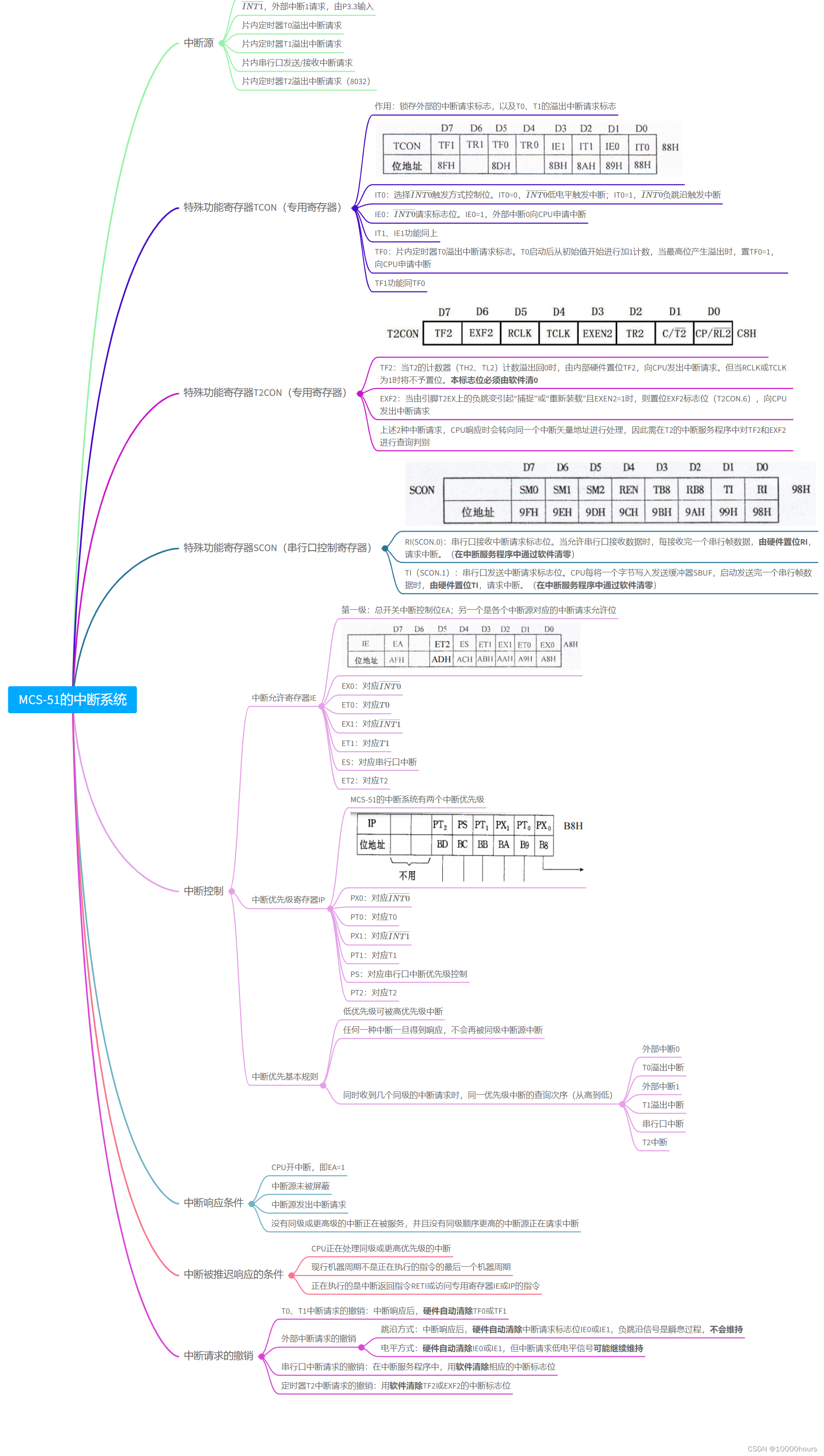
Notes text part
- MCS-51 The interrupt system of
- Interrupt source
- I N T 0 ‾ \overline{INT0} INT0, External interrupt 0 request , from P3.2 Input .
- I N T 1 ‾ \overline{INT1} INT1, External interrupt 1 request , from P3.3 Input
- On chip timer T0 Overflow interrupt request
- On chip timer T1 Overflow interrupt request
- On chip serial port sending / Receive interrupt request
- On chip timer T2 Overflow interrupt request (8032)
- special function register TCON( Special register )
effect : Latch the external interrupt request flag , as well as T0、T1 Overflow interrupt request flag

IT0: choice I N T 0 ‾ \overline{INT0} INT0 Trigger mode control bit .IT0=0, I N T 0 ‾ \overline{INT0} INT0 Low level trigger interrupt ;IT0=1, I N T 0 ‾ \overline{INT0} INT0 Negative jump edge triggers interrupt
IE0: I N T 0 ‾ \overline{INT0} INT0 Request flag bit .IE0=1, External interrupt 0 towards CPU Application interruption
IT1、IE1 The function is the same as above
TF0: On chip timer T0 Overflow interrupt request flag .T0 After starting, add... From the initial value 1 Count , When the highest bit overflows , Set up TF0=1, towards CPU Application interruption
TF1 Same function TF0
- special function register T2CON( Special register )

TF2: When T2 The counter of (TH2、TL2) Count overflow back 0 when , Set by internal hardware TF2, towards CPU Make an interrupt request . But when RCLK or TCLK by 1 It will not be set when . This flag bit must be cleared by the software 0
EXF2: When by pin T2EX The negative jump on the causes “ capture ” or “ Reload ” And EXEN2=1 when , Then set EXF2 Sign a (T2CON.6), towards CPU Make an interrupt request
Above 2 Interrupt request ,CPU When responding, it will turn to the same interrupt vector address for processing , Therefore, it is necessary to T2 Interrupt service program for TF2 and EXF2 Query and judge
- special function register SCON( Serial port control register )

RI(SCON.0): Serial port receives interrupt request flag bit . When the serial port is allowed to receive data , After receiving a serial frame data , Set by hardware RI, Request interrupt .( Reset by software in the interrupt service program )
TI(SCON.1): Serial port sends interrupt request flag bit .CPU Each byte is written to the transmit buffer SBUF, When starting to send a serial frame data , Set by hardware TI, Request interrupt .( Reset by software in the interrupt service program )
- Interrupt control
- Interrupt allow register IE
first stage : Master switch interrupt control bit EA; The other is the interrupt request permission bit corresponding to each interrupt source

EX0: Corresponding I N T 0 ‾ \overline{INT0} INT0
ET0: Corresponding T 0 T0 T0
EX1: Corresponding I N T 1 ‾ \overline{INT1} INT1
ET1: Corresponding T 1 T1 T1
ES: Corresponding serial port interrupt
ET2: Corresponding T2
- Interrupt priority register IP
MCS-51 The interrupt system of has two interrupt priorities

PX0: Corresponding I N T 0 ‾ \overline{INT0} INT0
PT0: Corresponding T0
PX1: Corresponding I N T 1 ‾ \overline{INT1} INT1
PT1: Corresponding T1
PS: Corresponding serial port interrupt priority control
PT2: Corresponding T2
- Interrupt priority basic rule
- Low priority can be interrupted by high priority
- Once any interrupt is responded , Will no longer be interrupted by the same level interrupt source
- When receiving interrupt requests from several peers at the same time , The query order interrupted by the same priority ( From high to low )
- External interrupt 0
- T0 Overflow interrupt
- External interrupt 1
- T1 Overflow interrupt
- Serial port interrupt
- T2 interrupt
- Interrupt allow register IE
- Interrupt response condition
- CPU Open the interrupt , namely EA=1
- The interrupt source is not masked
- Interrupt source sends interrupt request
- No peer or higher level interrupts are being serviced , And no interrupt source with higher peer order is requesting an interrupt
- Interrupt the condition that the response is delayed
- CPU Processing interrupts of the same or higher priority
- The current machine cycle is not the last machine cycle of the instruction being executed
- What is executing is the interrupt return instruction RETI Or access special registers IE or IP Instructions
- Revocation of interrupt request
- T0、T1 Revocation of interrupt request : After interrupt response , Hardware Auto clear TF0 or TF1
- Cancellation of external interrupt request
- Edge skipping mode : After interrupt response , Hardware Auto clear Interrupt request flag bit IE0 or IE1, The negative edge jump signal is a transient process , Will not maintain
- Level mode : Hardware Auto clear IE0 or IE1, But interrupt request low level signal May continue
- Revocation of serial port interrupt request : In the interrupt service program , use Software clear Corresponding interrupt flag bit
- Timer T2 Revocation of interrupt request : use Software clear TF2 or EXF2 Interrupt flag bit of
- Interrupt source
MCS-51 Timer / Counter
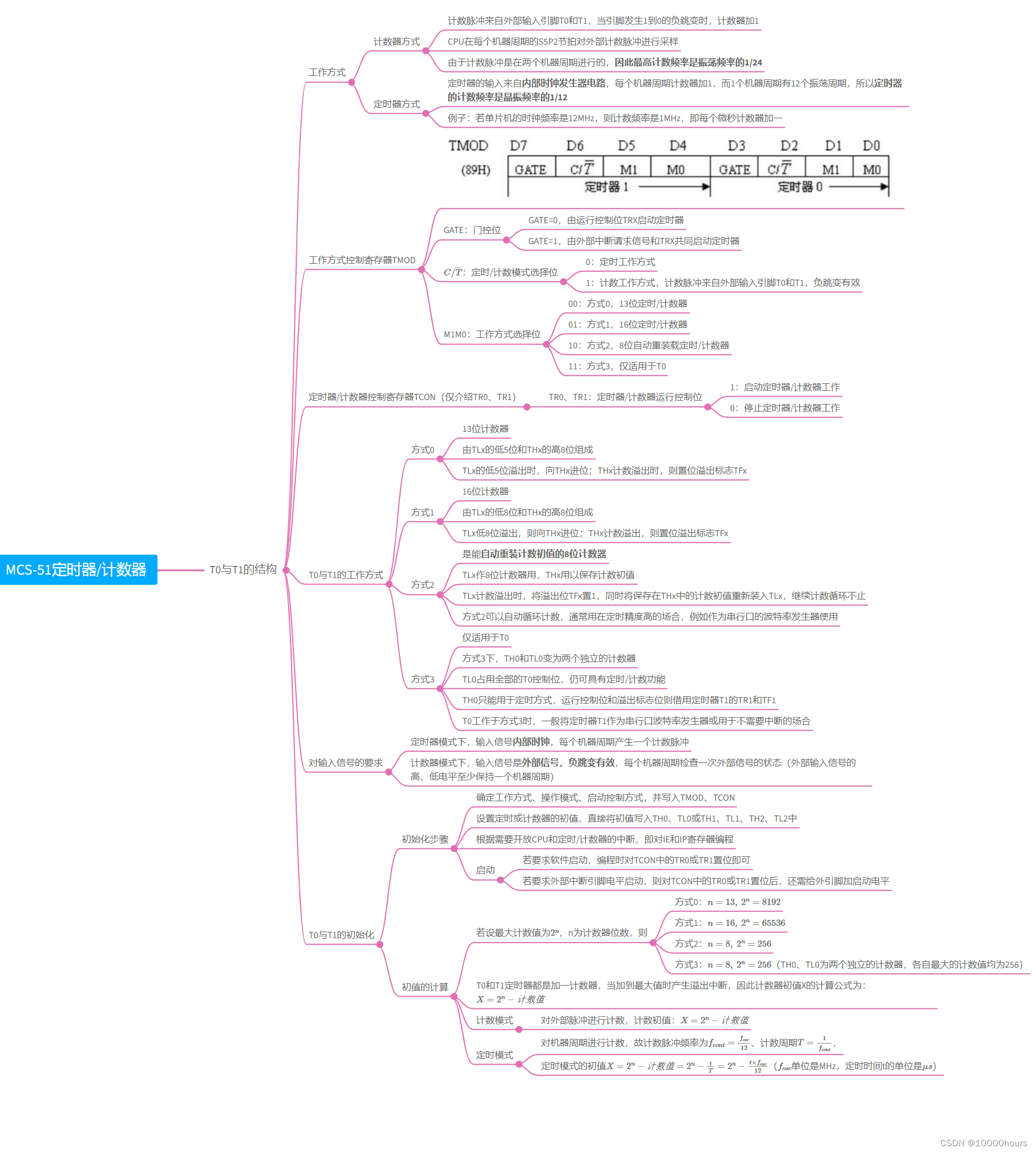
Note taking mind map
Notes text part
- MCS-51 Timer / Counter
- T0 And T1 Structure
- Operation mode
- Counter mode
- The counting pulse comes from the external input pin T0 and T1, When pin occurs 1 To 0 Negative jump time of , Counter plus 1
- CPU In every machine cycle S5P2 The beat samples the external counting pulse
- Because the counting pulse is carried out in two machine cycles , Therefore, the highest counting frequency is the oscillation frequency 1/24
- Timer mode
- The input of the timer comes from Internal clock generator circuit , Each machine cycle counter adds 1, and 1 Machine cycles have 12 Oscillation period , therefore The counting frequency of the timer is of the crystal oscillator frequency 1/12
- Example : If the clock frequency of MCU is 12MHz, Then the counting frequency is 1MHz, That is, add one to each microsecond counter
- Counter mode
- Working mode control register TMOD

GATE: Gate control position
- GATE=0, By the operation control bit TRX Start timer
- GATE=1, By external interrupt request signal and TRX Start the timer together
C / T ‾ C/\overline{T} C/T: timing / Count mode selection bit
- 0: Regular working mode
- 1: Counting works , The counting pulse comes from the external input pin T0 and T1, Negative jump is effective
M1M0: Working mode selection bit
- 00: The way 0,13 Bit timing / Counter
- 01: The way 1,16 Bit timing / Counter
- 10: The way 2,8 Bit automatic reload timing / Counter
- 11: The way 3, Only applicable to T0
- Timer / Counter control register TCON( Just introduce TR0、TR1)
- TR0、TR1: Timer / Counter operation control bit
- 1: Start timer / The counter works
- 0: Stop timer / The counter works
- TR0、TR1: Timer / Counter operation control bit
- T0 And T1 How it works
- The way 0
- 13 Bit counter
- from TLx It's low 5 Bit and THx The height of 8 A composition
- TLx It's low 5 Bit overflow , towards THx carry ;THx When count overflows , Then set the overflow flag TFx
- The way 1
- 16 Bit counter
- from TLx It's low 8 Bit and THx The height of 8 A composition
- TLx low 8 Bit overflow , to THx carry ;THx Count overflow , Then set the overflow flag TFx
- The way 2
- Yes Automatic reload count initial value 8 Bit counter
- TLx do 8 For bit counter ,THx Used to save the initial value of the count
- TLx When count overflows , Will overflow TFx Set up 1, At the same time, it will be saved in THx Reload the initial count value in TLx, Continue counting cycle more than
- The way 2 It can count automatically , It is usually used in occasions with high timing accuracy , For example, it is used as a baud rate generator of serial port
- The way 3
- Only applicable to T0
- The way 3 Next ,TH0 and TL0 Become two independent counters
- TL0 Occupy all T0 Control bits , Still have timing / Counting function
- TH0 It can only be used in timing mode , The operation control bit and overflow flag bit borrow timer T1 Of TR1 and TF1
- T0 Work in a way 3 when , Generally, the timer T1 As a serial port baud rate generator or for occasions that do not need interruption
- The way 0
- Requirements for input signals
- In timer mode , Input signal Internal clock , Each machine cycle generates a counting pulse
- In counter mode , The input signal is External signals , Negative jump is effective , Check the status of external signals every machine cycle ( High of external input signal 、 Keep the low level for at least one machine cycle )
- T0 And T1 The initialization
- Initialization steps
- Determine how it works 、 Operation mode 、 Start control mode , And write TMOD、TCON
- Set the initial value of timer or counter , Write the initial value directly TH0、TL0 or TH1、TL1、TH2、TL2 in
- Open as needed CPU And timing / Interrupt of counter , to IE and IP Register programming
- start-up
- If software startup is required , When programming TCON Medium TR0 or TR1 Set it
- If the external interrupt pin level is required to start , On the other hand TCON Medium TR0 or TR1 After setting , It is also necessary to add the starting level to the external pin
- Calculation of initial value
- If the maximum count value is 2 n 2^n 2n,n Is the number of counter digits , be
- The way 0: n = 13 , 2 n = 8192 n=13, \ 2^n=8192 n=13, 2n=8192
- The way 1: n = 16 , 2 n = 65536 n=16, \ 2^n=65536 n=16, 2n=65536
- The way 2: n = 8 , 2 n = 256 n=8, \ 2^n=256 n=8, 2n=256
- The way 3: n = 8 , 2 n = 256 n=8, \ 2^n=256 n=8, 2n=256(TH0、TL0 For two independent counters , The maximum count values of each are 256)
- T0 and T1 All timers add one counter , When it is added to the maximum value, an overflow interrupt is generated , Therefore, the initial value of the counter X The calculation formula of is : X = 2 n − meter Count value X=2^n- Count value X=2n− meter Count value
- Count mode
- Count external pulses , Count the initial value : X = 2 n − meter Count value X=2^n- Count value X=2n− meter Count value
- Timing mode
- Count machine cycles , Therefore, the counting pulse frequency is f c o n t = f o s c 12 f_{cont}=\cfrac{f_{osc}}{12} fcont=12fosc、 Count period T = 1 f c o n t T=\cfrac{1}{f_{cont}} T=fcont1,
- Initial value of timing mode X = 2 n − meter Count value = 2 n − t T = 2 n − t × f o s c 12 X=2^n- Count value =2^n-\frac{t}{T}=2^n-\frac{t\times f_{osc}}{12} X=2n− meter Count value =2n−Tt=2n−12t×fosc( f o s c f_{osc} fosc The unit is MHz, Timing time t Its unit is μ s \mu s μs)
- If the maximum count value is 2 n 2^n 2n,n Is the number of counter digits , be
- Initialization steps
- Operation mode
- T0 And T1 Structure
Timer / Counter exercises
explain : This question is one of the previous exams , The correctness of my writing has not been verified .
8031 Single chip system , Crystal vibration is 6MHz. Please write the program , Using a timer T0 Method 2 , stay P1.0 Output one cycle 250μs、 Duty ratio 2:5 The square wave ( Here's the picture ):
(1) Calculate the initial value
Using timer mode , Count value = t × f o s c 12 = 50 μ s × 6 M H z 12 = 25 t\times \frac{f_{osc}}{12}=50\mu s \times \frac{6MHz}{12}=25 t×12fosc=50μs×126MHz=25, Every time 50 μ s 50 \mu s 50μs Create an interrupt
Initial value X = 2 8 − 25 = 231 = E 7 H 2^8 - 25 = 231 = E7H 28−25=231=E7H
(2) Programming
      ORG 0000H
      LJMP MAIN
      ORG 000BH        ;T0 Interrupt entry address of
      LJMP INT

      ORG 0100H
MAIN: MOV SP,#60H
      MOV TMOD, #02H   ;0010
      MOV TH0, #0E7H
      MOV TL0, #0E7H   ;T0 Assign initial value to
      SETB EA          ; General interruption
      SETB ET0         ; allow T0 interrupt
      SETB TR0         ; start-up T0
      SETB P1.0
      CLR F0           ;F0=0 when , Output 100 Microsecond high level ;F0=1, Output low level
      MOV R0, #02H     ; Output two 50 Microsecond high level
WAIT: AJMP WAIT        ; Wait for the interruption
INT:  JB INT1
	  SETB P1.0        ;P1.0 Output high level
      DJNZ R0, INT     ; If the high level maintenance time does not reach 100 Microseconds continue to maintain high level
      SETB F0          ; Set up F0=1, Output low level
      MOV R0, #03H     ; Duration ( A time period is 50 Microsecond ) Number
      RETI
INT1: CLR P1.0         ;P1.0 Output low level
      DJNZ R0, INT1    ; If the low level maintenance time does not reach 150 Microseconds remain low
      CLR F0           ; Set up F0=0, Output high level
      MOV R0, #02H     ; Duration ( A time period is 50 Microsecond ) Number
      RETI
MCS-51 Serial port of
Note taking mind map
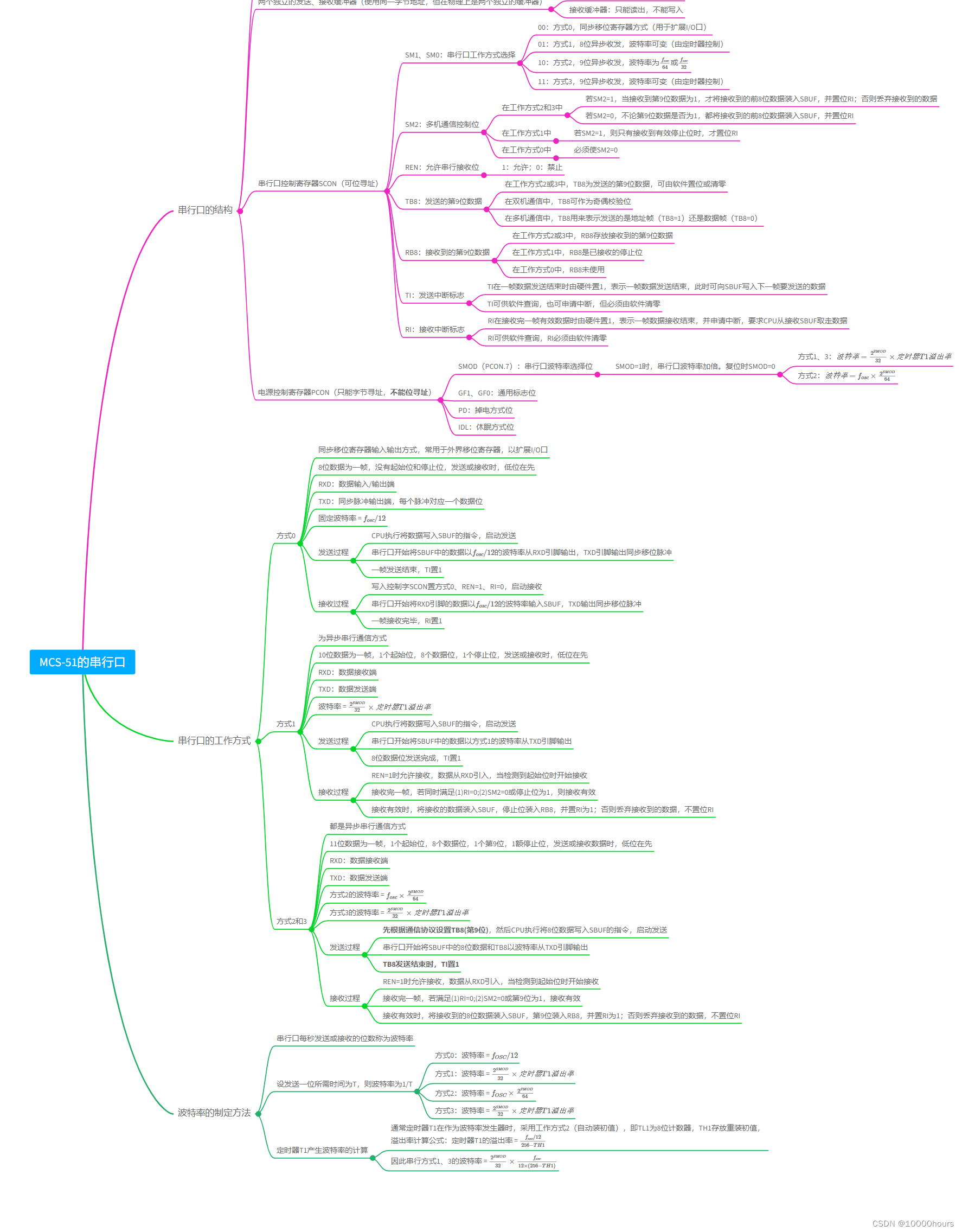
Notes text part
- MCS-51 Serial port of
- Structure of serial port
- Full duplex serial asynchronous communication port
- Two independent transmissions 、 Receive buffer ( Use the same byte address , But physically, they are two independent buffers )
- Transmit buffer : Write only , Can't read
- Receive buffer : Can only read , Cannot write
- Serial port control register SCON( Addressable addressing )
- SM1、SM0: Serial port working mode selection
- 00: The way 0, Synchronous shift register mode ( Used to extend I/O mouth )
- 01: The way 1,8 Bit asynchronous transceiver , The baud rate is variable ( Controlled by a timer )
- 10: The way 2,9 Bit asynchronous transceiver , The baud rate is f o s c 64 \cfrac{f_{osc}}{64} 64fosc or f o s c 32 \cfrac{f_{osc}}{32} 32fosc
- 11: The way 3,9 Bit asynchronous transceiver , The baud rate is variable ( Controlled by a timer )
- SM2: Multi machine communication control bit
- In the way it works 2 and 3 in
- if SM2=1, When receiving the second 9 Bit data is 1, Will receive before 8 Bit data loading SBUF, Juxtaposition RI; Otherwise, the received data will be discarded
- if SM2=0, Regardless of the second 9 Whether the bit data is 1, Will be received before 8 Bit data loading SBUF, Juxtaposition RI
- In the way it works 1 in
- if SM2=1, Then only when a valid stop bit is received , Just set RI
- In the way it works 0 in
- Must make SM2=0
- In the way it works 2 and 3 in
- REN: Allows serial reception of bits
- 1: allow ;0: prohibit
- TB8: Send the 9 Bit data
- In the way it works 2 or 3 in ,TB8 For the number sent 9 Bit data , It can be set or reset by software
- In dual computer communication ,TB8 It can be used as parity bit
- In multi computer communication ,TB8 It is used to indicate that the address frame is sent (TB8=1) Or data frame (TB8=0)
- RB8: The... Received 9 Bit data
- In the way it works 2 or 3 in ,RB8 Store the received No 9 Bit data
- In the way it works 1 in ,RB8 Is the received stop bit
- In the way it works 0 in ,RB8 not used
- TI: Send interrupt flag
- TI At the end of sending a frame of data, the hardware sets 1, Indicates the end of sending a frame of data , At this time, you can go to SBUF Write the data to be sent in the next frame
- TI Available for software query , You can also apply for interruption , But it must be cleared by the software
- RI: Receive interrupt flag
- RI After receiving a frame of valid data, the hardware sets 1, Indicates the end of data reception of one frame , And apply for interruption , requirement CPU Receive from SBUF Taking the data
- RI Available for software query ,RI Must be cleared by software
- SM1、SM0: Serial port working mode selection
- Power control register PCON( Byte addressing only , It can't be bit addressable )
- SMOD(PCON.7): Serial port baud rate selection bit
- SMOD=1 when , Double baud rate of serial port . Reset time SMOD=0
- The way 1、3: wave , rate = 2 S M O D 32 × set when device T 1 overflow Out rate Baud rate = \cfrac{2^{SMOD}}{32}\times Timer T1 Overflow rate wave , rate =322SMOD× set when device T1 overflow Out rate
- The way 2: wave , rate = f o s c × 2 S M O D 64 Baud rate =f_{osc}\times \frac{2^{SMOD}}{64} wave , rate =fosc×642SMOD
- SMOD=1 when , Double baud rate of serial port . Reset time SMOD=0
- GF1、GF0: General flags
- PD: Power down mode bit
- IDL: Sleep mode bit
- SMOD(PCON.7): Serial port baud rate selection bit
- Working mode of serial port
- The way 0
- Synchronous shift register input and output mode , Commonly used in external shift registers , In order to expand I/O mouth
- 8 Bit data is one frame , There are no start and stop bits , When sending or receiving , Low first
- RXD: data input / Output terminal
- TXD: Synchronous pulse output terminal , Each pulse corresponds to a data bit
- Fixed baud rate = f o s c / 12 f_{osc}/12 fosc/12
- Sending process
- CPU Execute writing data SBUF Instructions , Start sending
- The serial port will start SBUF Data in to f o s c / 12 f_{osc}/12 fosc/12 The baud rate is from RXD Pin out ,TXD Pin output synchronous shift pulse
- One frame transmission ends ,TI Set up 1
- Reception process
- Write control word SCON Setting mode 0、REN=1、RI=0, Start receiving
- The serial port will start RXD The data of the pin is in f o s c / 12 f_{osc}/12 fosc/12 Baud rate input SBUF,TXD Output synchronous shift pulse
- One frame is received ,RI Set up 1
- The way 1
- Asynchronous serial communication
- 10 Bit data is one frame ,1 Starting bits ,8 Data bits ,1 Stop bits , When sending or receiving , Low first
- RXD: Data receiver
- TXD: Data sending end
- Baud rate = 2 S M O D 32 × set when device T 1 overflow Out rate \frac{2^{SMOD}}{32}\times Timer T1 Overflow rate 322SMOD× set when device T1 overflow Out rate
- Sending process
- CPU Execute writing data SBUF Instructions , Start sending
- The serial port will start SBUF The data in is in the form 1 The baud rate is from TXD Pin out
- 8 Bit by bit transmission complete ,TI Set up 1
- Reception process
- REN=1 Allow to receive when , Data from RXD introduce , Start receiving when the start bit is detected
- After receiving a frame , If we meet at the same time (1)RI=0;(2)SM2=0 Or the stop bit is 1, Then the reception is valid
- When the reception is valid , Load the received data SBUF, Stop bit loading RB8, Juxtaposition RI by 1; Otherwise, the received data will be discarded , Not set RI
- The way 2 and 3
- Are asynchronous serial communication
- 11 Bit data is one frame ,1 Starting bits ,8 Data bits ,1 First paragraph 9 position ,1 Stop bit , When sending or receiving data , Low first
- RXD: Data receiver
- TXD: Data sending end
- The way 2 Baud rate = f o s c × 2 S M O D 64 f_{osc}\times \frac{2^{SMOD}}{64} fosc×642SMOD
- The way 3 Baud rate = 2 S M O D 32 × set when device T 1 overflow Out rate \frac{2^{SMOD}}{32}\times Timer T1 Overflow rate 322SMOD× set when device T1 overflow Out rate
- Sending process
- First set according to the communication protocol TB8( The first 9 position ), then CPU The executive will 8 Bit data write SBUF Instructions , Start sending
- The serial port will start SBUF Medium 8 Bits of data and TB8 From... At baud rate TXD Pin out
- TB8 At the end of sending ,TI Set up 1
- Reception process
- REN=1 Allow to receive when , Data from RXD introduce , Start receiving when the start bit is detected
- After receiving a frame , If meet (1)RI=0;(2)SM2=0 Or the first 9 Position as 1, The reception is valid
- When the reception is valid , Will receive 8 Bit data loading SBUF, The first 9 Bit loading RB8, Juxtaposition RI by 1; Otherwise, the received data will be discarded , Not set RI
- The way 0
- How to formulate baud rate
- The number of bits sent or received by the serial port per second is called the baud rate
- Set the time required to send one bit as T, Then the baud rate is 1/T
- The way 0: Baud rate = f O S C / 12 f_{OSC}/12 fOSC/12
- The way 1: Baud rate = 2 S M O D 32 × set when device T 1 overflow Out rate \cfrac{2^{SMOD}}{32}\times Timer T1 Overflow rate 322SMOD× set when device T1 overflow Out rate
- The way 2: Baud rate = f O S C × 2 S M O D 64 f_{OSC}\times \frac{2^{SMOD}}{64} fOSC×642SMOD
- The way 3: Baud rate = 2 S M O D 32 × set when device T 1 overflow Out rate \frac{2^{SMOD}}{32}\times Timer T1 Overflow rate 322SMOD× set when device T1 overflow Out rate
- Timer T1 Calculation of baud rate
- Usually the timer T1 As a baud rate generator , Adopt a way of working 2( Automatically install the initial value ), namely TL1 by 8 Bit counter ,TH1 Store the initial value of reassembly , Overflow rate calculation formula : Timer T1 The spillover rate of = f o s c / 12 256 − T H 1 \cfrac{f_{osc}/12}{256-TH1} 256−TH1fosc/12
- So serial mode 1、3 Baud rate = 2 S M O D 32 × f o s c 12 × ( 256 − T H 1 ) \cfrac{2^{SMOD}}{32}\times \cfrac{f_{osc}}{12\times (256-TH1)} 322SMOD×12×(256−TH1)fosc
- Structure of serial port
边栏推荐
- PACP学习笔记一:使用 PCAP 编程
- Smart cloud health listed: with a market value of HK $15billion, SIG Jingwei and Jingxin fund are shareholders
- 记一次 .NET 某新能源系统 线程疯涨 分析
- JS缓动动画原理教学(超细节)
- Practical example of propeller easydl: automatic scratch recognition of industrial parts
- QQ的药,腾讯的票
- Introduction and basic use of stored procedures
- How to reset Firefox browser
- Why can basic data types call methods in JS
- shell 批量文件名(不含扩展名)小写改大写
猜你喜欢
随机推荐
[learning notes] zkw segment tree
Unity build error: the name "editorutility" does not exist in the current context
简单好用的代码规范
[QNX Hypervisor 2.2用户手册]6.3.4 虚拟寄存器(guest_shm.h)
Practical example of propeller easydl: automatic scratch recognition of industrial parts
工具箱之 IKVM.NET 项目新进展
分屏bug 小记
MongoDB 分片总结
OSI 七层模型
“新红旗杯”桌面应用创意大赛2022
Sequoia China completed the new phase of $9billion fund raising
Sed of three swordsmen in text processing
如何让electorn打开的新窗口在window任务栏上面
[learning notes] segment tree selection
1、深拷贝 2、call apply bind 3、for of for in 区别
【Presto Profile系列】Timeline使用
Storage principle inside mongodb
Pcap learning notes II: pcap4j source code Notes
[learning notes] agc010
详细介绍六种开源协议(程序员须知)




![[Presto profile series] timeline use](/img/c6/83c4fdc5f001dab34ecf18c022d710.png)