当前位置:网站首页>Lidar: introduction and usage of ouster OS
Lidar: introduction and usage of ouster OS
2022-07-07 02:14:00 【The moon shines on the silver sea like a dragon】
Laser radar :Ouster Product introduction and usage
Preface
Ouster Company profile
Ouster Inc. Founded on 2015 year , By the lidar field Unicorn Quanergy Former co-founder of Angus Pacala found , Headquartered in San Francisco .
It is a manufacturer of laser radar , Products include OS0、OS1、OS2 Three series 9 Laser radar .
Ouster Committed to building a new generation of lidar sensors for large-scale applications , Committed to improving product resolution 、 Parameters such as visual distance and overall dimension , be based on MBF Multi beam flash basic patent , Combined independence ASIC IP Design implementation capability , Dedicated to unmanned systems 、 Surveying and mapping 、 Security monitoring 、 Industrial Engineering Automation 、 Intelligent transportation / logistics / Industries and scenes such as cities , Higher performance 、 More reliable 、 More cost-effective depth vision products and 3D Perceived solutions .
Unlike traditional lidar, it contains thousands of components ,Ouster There is only a chip level laser array and a CMOS sensor , Greatly reduced the price , Improved performance and reliability .
Ouster Product series introduction
Ouster The product line is very simple and clear , Yes 3 The two series are :
- OS0
- OS1
- OS2
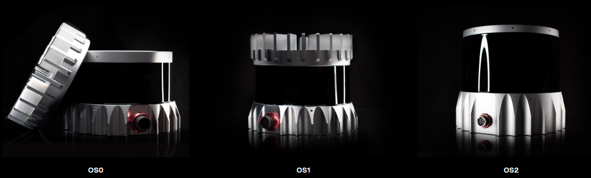
They have different characteristics
OS0 Its main feature is the super wide field angle , The vertical field of view angle can reach 90°, But the detection distance is the shortest , by 50m
OS1 On average , The vertical field angle is 45°, The detection distance is 120m
OS2 Its main feature is long-distance detection , The minimum vertical field angle is 22.5°, The detection distance is 240m
When using, you can choose different series of products according to the application scenario .
OS1 Detailed introduction
Because of the use of OS1-64 Products , Its parameters are introduced in detail here .
First, let's take a picture of the point cloud of a frame of data :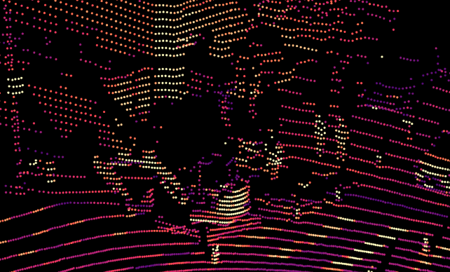
You can choose the distribution form of point cloud , There are three kinds of :
- Uniform distribution
- Central encryption
- Downward distribution
The schematic diagrams of the three types are as follows :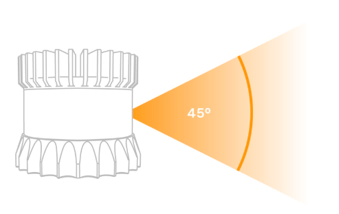
Uniform distribution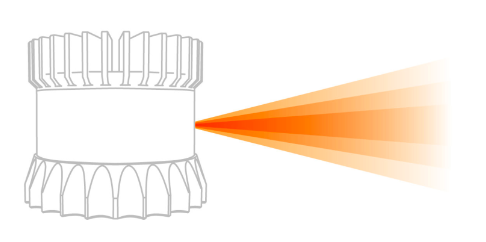
Central encryption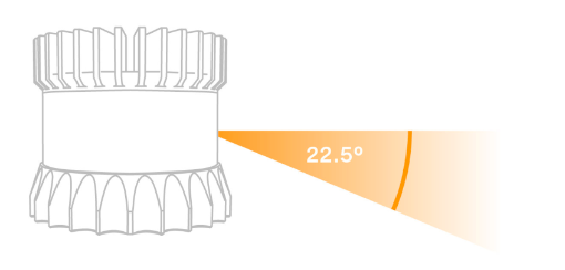
Downward distribution
It can be seen that the bus bundle is fixed 64, So the more backward the vertical field of view angle is smaller .
OS1 main parameter
| Horizontal resolution | 512,1024,2048 |
|---|---|
| Vertical resolution | 64 Line |
| Detection distance | 120 m |
| Vertical field angle | 45° (±22.5º) |
| Vertical angular resolution | 0.35º – 2.8º ( Multiple choice ) |
| Measurement accuracy | ±0.7 – 5 cm |
| Points per second | 1,310,720 |
| OS1-64 | 10 Hz,20 Hz |
| Power waste | 14 – 20 W |
| weight | 447 g |
| Protection level | IP68, IP69K |
In addition, the characteristics that laser radar often pays attention to are also summarized below :
- Optional PTP and NMEA/PPS Time synchronization
- Output : Detection distance 、 Strength 、 Reflectivity 、 Environmental near infrared 、 azimuth 、 Time stamp
- Dual echo mode , The strongest echo and the second strongest echo
Hardware connection
Hardware connection is not recommended if it is complicated , It is the interface directly connected to the radar sensor .
OS1 It can be operated without an interface box . When using , Conduct wiring according to pin assignment as described below .
The reason why it is not recommended is that there is any equipment damage due to voltage and current , The manufacturer is not responsible .
Let's look at the conventional usage , The manufacturer will also provide a connector .
It's like this 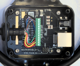
This connection is simple , The interface on the left is connected to radar , The Internet port on the right connects to the computer , There is also a power supply port on the right , Just supply power .
One more GPS Time hardware synchronization port ,
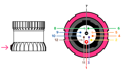
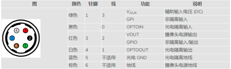
The side view on the right is as follows 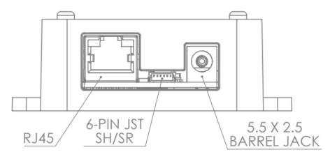
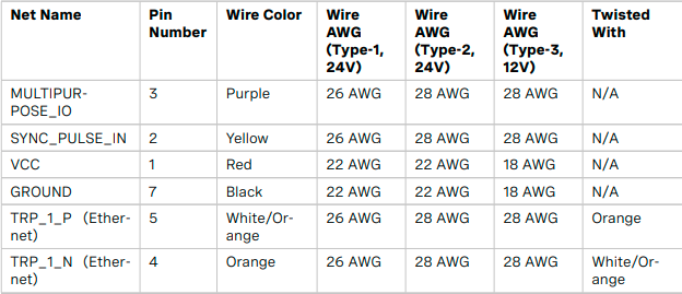
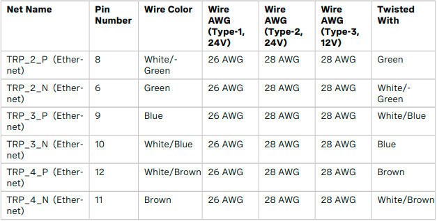
Network port and power supply port needless to say , The pins of the clock synchronization port are defined as follows :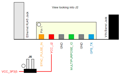
The overall connection diagram is as follows :
Ouster ROS drive
ROS The version is Kinetic
GitHub Cloned
git clone https://github.com/ouster-lidar/ouster_example.git
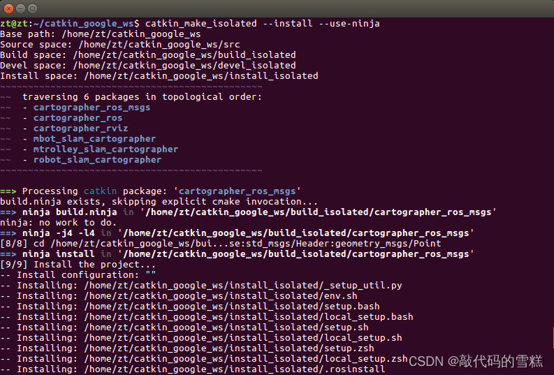
Then compile Ouster ROS
After the compilation is successful, you will be prompted as follows :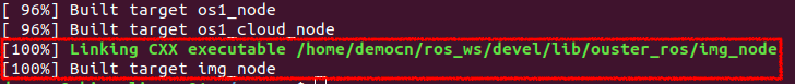
If the compilation encounters the following problems :
fatal error: tclap/CmdLine.h: No such file or directory
It can be done by
sudo apt install libtclap-dev
solve
stay ouster_example/ouster_ros Under the path os1.launch This launch file
roslaunch os1.launch os1_hostname:=< radar IP> os1_udp_dest:=< This machine IP> viz:=true image:=true
Through the above instructions You can run this launch file ,
os1_hostname:=: For radar IP Address

os1_udp_dest:=: For this machine IP Address

viz:=:true -  Turn on  Ouster Visualizer  Show point clouds and 2D Ring view , The default is false

image:=:true -  Turn on 2D Ring view node , Can be found in rviz View in , The default is false

lidar_mode:=:  Radar operation mode options , Optional 512x10 | 512x20 | 1024x10 | 1024x20 | 2048x10,  The default is 1024x10
The above instructions are configured as required
And then in rviz You can see some clouds inside 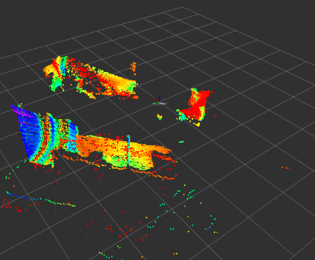
边栏推荐
- [leetcode] day97 remove linked list elements
- Metaforce force meta universe development and construction - fossage 2.0 system development
- 新一代云原生消息队列(一)
- The GPG keys listed for the "MySQL 8.0 community server" repository are already ins
- NPM install compilation times "cannot read properties of null (reading 'pickalgorithm')“
- centos8 用yum 安装MySQL 8.0.x
- How to use strings as speed templates- How to use String as Velocity Template?
- Make DIY welding smoke extractor with lighting
- ROS learning (21) robot slam function package -- installation and testing of orbslam
- Shortcut keys commonly used in idea
猜你喜欢
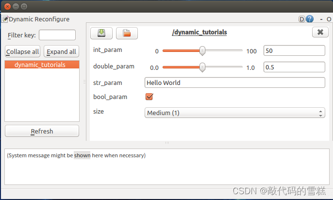
ROS learning (26) dynamic parameter configuration
FLIR blackfly s industrial camera: configure multiple cameras for synchronous shooting
SchedulX V1.4.0及SaaS版发布,免费体验降本增效高级功能!
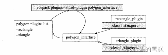
ROS learning (24) plugin
ROS learning (XIX) robot slam function package cartographer
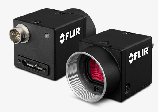
Flir Blackfly S USB3 工业相机:计数器和定时器的使用方法

猿桌派第三季开播在即,打开出海浪潮下的开发者新视野

张平安:加快云上数字创新,共建产业智慧生态

Flir Blackfly S 工业相机:通过外部触发实现多摄像头同步拍摄
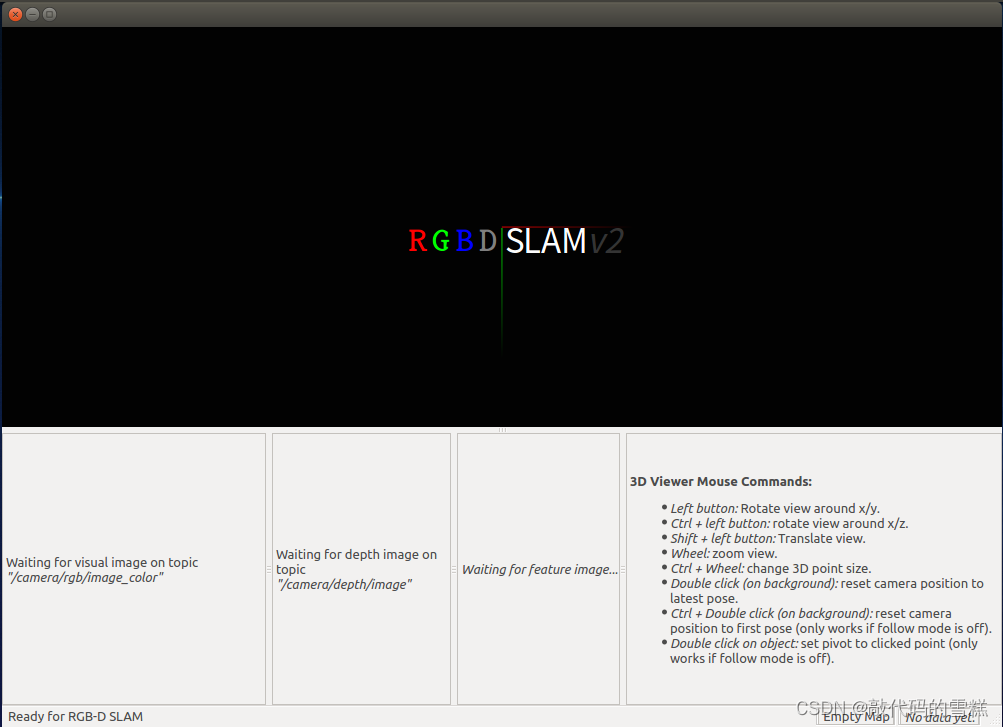
ROS learning (XX) robot slam function package -- installation and testing of rgbdslam
随机推荐
ROS learning (26) dynamic parameter configuration
ROS学习(25)rviz plugin插件
低代码平台中的数据连接方式(上)
ROS learning (XIX) robot slam function package cartographer
centos8安装mysql报错:The GPG keys listed for the “MySQL 8.0 Community Server“ repository are already ins
Recommended collection!! Which is the best flutter status management plug-in? Please look at the ranking list of yard farmers on the island!
[unique] what is the [chain storage structure]?
2022 system integration project management engineer examination knowledge point: Mobile Internet
Collection recommandée!! Quel plug - in de gestion d'état flutter est le plus fort? Regardez le classement des manons de l'île, s'il vous plaît!
【论文阅读|深读】DNGR:Deep Neural Networks for Learning Graph Representations
猿桌派第三季开播在即,打开出海浪潮下的开发者新视野
云原生混部最后一道防线:节点水位线设计
一片叶子两三万?植物消费爆火背后的“阳谋”
UC伯克利助理教授Jacob Steinhardt预测AI基准性能:AI在数学等领域的进展比预想要快,但鲁棒性基准性能进展较慢
Metaforce force meta universe development and construction - fossage 2.0 system development
Redis configuration class redisconfig
Analyze "C language" [advanced] paid knowledge [II]
张平安:加快云上数字创新,共建产业智慧生态
Seconds understand the delay and timing function of wechat applet
Integrated navigation: product description and interface description of zhonghaida inav2