当前位置:网站首页>Whole process analysis of unity3d rendering pipeline
Whole process analysis of unity3d rendering pipeline
2022-07-07 15:44:00 【Listen to the rain outside the window】
Catalog
Render pipeline ( Assembly line , technological process )
Render pipeline ( Assembly line , technological process )
Statement : This article refers to 《Real-Time Rendering》 The book summarizes and cites some of the pictures
One 、 Rendering tasks
The task of rendering is actually to start from a three-dimensional scene , Render it to generate a two-dimensional image for human eyes to observe . Tell me more about it , Namely CPU and GPU coordination , take 3D Coordinates of each object in the scene , texture , Materials and other information are transformed into images that can be seen by human eyes and mapped onto the screen .
Two 、 Three stages
The three stages of rendering are generally divided into , Application stage , Geometric stage and rasterization stage , The general process is shown in the figure below 1
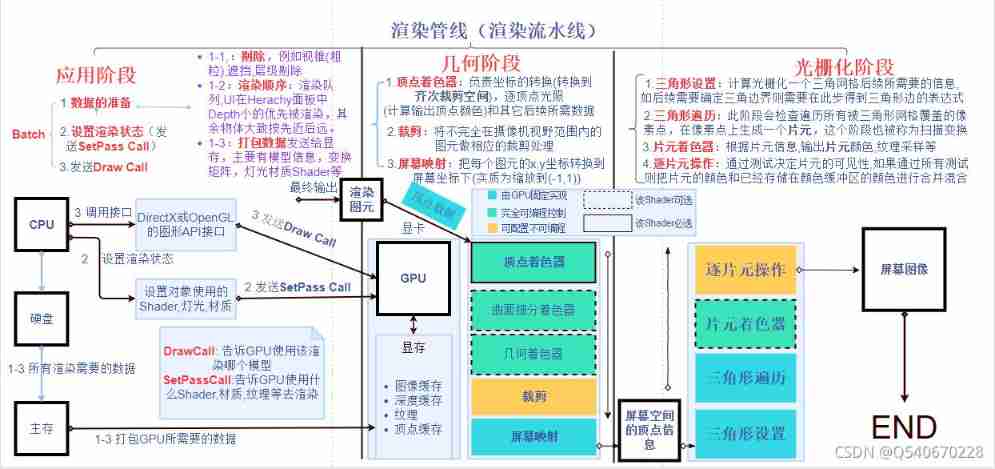
chart 1 Rendering pipeline flow chart
The flow chart of the operation objects in the three stages can be roughly referred to chart 2
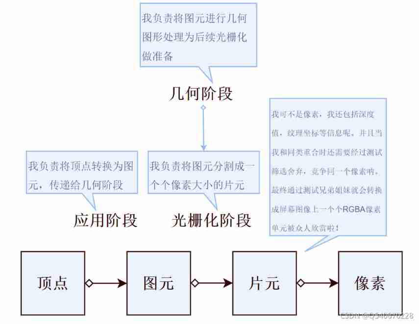
chart 2 Render pipeline operation object flowchart
1、 Application stage
This stage consists of CPU Handle , The main task is for the next GPU The rendering operation of provides the required geometric information , That is, output rendering elements (rending primitives) For use in subsequent stages . A rendering primitive is a geometric shape composed of several vertices , spot , Line , triangle , A polygon face can be an entity .
1-1: Data preparation
First step The unnecessary data should be eliminated first , Such as the visual cone in the unit of bounding box ( coarse-grained ) To eliminate , Occlusion culling , Level culling and so on .
The second step according to UI The object is Herachy Order of panel depth values (DFS Depth-first search ) Set the order of rendering , The rest of the objects can roughly follow the rule of getting close to the camera first and then getting far, and make a queue order for all objects drawn in the subsequent cycle .
The third step First read all the required rendering data from the hard disk to the main memory , And then GPU The data needed for rendering is packaged and sent to video memory (GPU Generally, there is no access to the main memory , And it is faster to exchange with video memory ).
The details of the packed data are shown in Figure 3
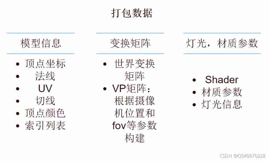
chart 3 Packaged data information
1-2: Set render state
Render states include shaders (Shader), texture , texture of material , Lights and so on .
Setting the render state is essentially , tell GPU Which one should I use Shader, texture , Material, etc. to render the mesh body of the model , This process is SetPassCall. When using different materials or different materials under the same material Pass You need to set and switch multiple rendering States , Will increase SetPassCall therefore SetPassCall The number of times can also reflect the performance .
1-3: send out DrawCall
When you receive a DrawCall when ,GPU Will follow orders , according to Render states And the input vertex information Appoint The mold ( grid ) Perform computational rendering .
CPU By calling graph API Interface ( glDrawElements (OpenGl Primitive rendering functions in ) perhaps DrawIndexedPrimitive (DirectX Vertex drawing method in ) ) command GPU The operation of rendering the specified object once is DrawCall. This process is essentially telling GPU Which model data should be used ( graphics API The function of the function is to CPU The calculated vertex data is rendered ).
In the application stage, there are three terms that are very important to measure performance indicators Now I'll talk about it again
DrawCall:CPU Every time the graph is called API Interface command GPU The operation of rendering is called once DrawCall.
SetPassCall: Set up / Switch the rendering state once .
Batch: Load data into video memory , Set render state ,CPU call GPU The process of rendering is called a Batch.
notes : One Batch Contains at least one DrawCall
2、 Geometric stage
The geometric stage consists of GPU To deal with , It deals with almost all the rendering related to geometry . Such as painted objects , Location , shape . When dealing with objects in the geometric phase Rendering elements , Perform vertex by vertex and polygon by polygon operations . The main task is to transform vertex coordinates into screen space , To supply the next raster for processing . The specific output information is , Transformed screen two vertex coordinates , The depth value of the vertex , To color , Normals and other information .
Next, we will explain the main assembly line stage of geometry stage :
2-1: Vertex shader
The first stage of the assembly line , It can be controlled by programming . Input from CPU Sent vertex information , The vertex shader is called once for each vertex . Its main work is : Coordinate transformation and per vertex lighting ( Optional , Calculate the output top The color value of the dot ). Coordinate conversion is a task that must be completed . It transforms vertex coordinates from model space to homogeneous clipping space .( Homogeneous clipping space is not screen space , yes xyz Put them all down to -1 To 1 Space ), The specific process can refer to figure 4
( Mention it : here GPU The relationship between vertices is not clear to the vertices being processed , Just treat each vertex indiscriminately , can It well reflects the separation of various components , Reduce coupling )
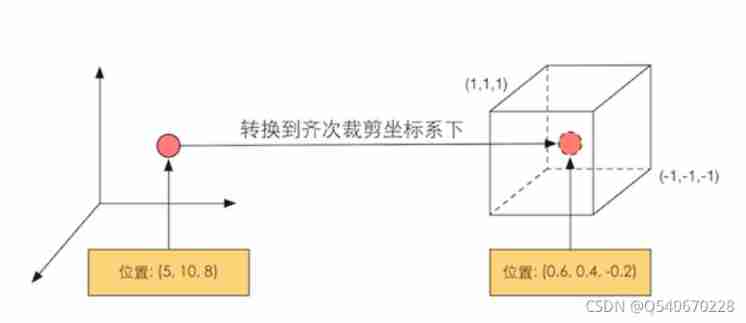
chart 4 Coordinate transformation
2-2: tailoring
seeing the name of a thing one thinks of its function , It is the process of getting rid of unnecessary data objects . Because the scene is usually large , The field of view of the camera may not cover all scene objects , Clipping is proposed to remove objects outside the field of view of the camera .
There are three relationships between an element and a camera : Completely in view 、 Part of it is in the field of vision 、 Completely in the field of vision . What is completely in the field of vision is passed to the next assembly line stage , Those who are completely in the field of vision will not pass down , And the part in the field of vision needs to be processed , It's cutting .
The figure below ( chart 5) It shows a cutting process :
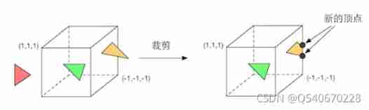
chart 5 The cutting process
From the figure 5 It can be clearly seen , Except that elements completely inside and outside the space are preserved and discarded , Elements partially in space ( Yellow triangle ) It's going to be cut , The new vertex will be generated at the boundary of space , The original vertex on the outside will be discarded .
2-3: Screen mapping
Through calculation, the objects of the actual scene are mapped to the screen , In essence, it is the scaling of coordinates , Refer to the figure 6
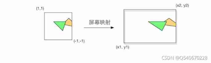
chart 6 Screen mapping
3、 Grating stage
This stage is still controlled by GPU To deal with . This phase will use the data passed in the previous phase ( Vertex positions in screen coordinate system and additional information related to them , Such as depth value (z coordinate )、 Normal direction 、 Angle of view, direction, etc .) To generate pixels on the screen , And render the final image . The main task of rasterization is Decide which pixels in the rendered primitive should be drawn on the screen , Then merge and blend the colors .
3-1: Triangle settings
Its main task is to provide the information needed for subsequent rasterization . for example , In the subsequent stage, we need to judge whether the pixels are covered by the triangular mesh , The vertex information obtained in the last stage alone cannot determine the coverage of the boundary , You also need information about the edges of the triangle mesh , So at this stage, we need to calculate the expression of the edge for subsequent judgment . Its output is to prepare for the next stage .
3-2: Triangle traversal
The triangle traversal stage will judge which pixels are covered by a triangle mesh according to the calculation results of the previous stage , The vertex information of the three vertices of the triangular mesh is used to interpolate the entire coverage area . The detailed process is described below :
This stage will traverse all pixels , Judge whether it is covered by triangular mesh ( use 3-1 The result of the calculation ) , If covered , Then a fragment is generated on this pixel . A slice is not just a pixel , It also contains a collection of many states , These states are used to finally calculate, detect and filter the final color of each pixel .( Some states include : Screen coordinates , Depth value , Normals inherited from geometric stages , Texture and so on ).
The information of the state of a slice is obtained by interpolating the information of the three vertices of the triangular mesh where it is located , For example, calculate the depth of the patch element at the center of gravity of the triangular mesh Here's the picture ( chart 7)

chart 7 Slice state information interpolation
The final output is a sequence of slices containing multiple slices
3-3: Chip shader
Very important programmable shader stage . The input of slice shaders is the result of interpolation of vertex information in the previous stage , Output the color value of each slice . At this stage, many important rendering technologies can be completed on demand , One of the most important technologies is Texture sampling .
Texture sampling
For texture sampling in a slice shader , First in Vertex shader Phase outputs the texture coordinates corresponding to each vertex , Then the texture coordinates corresponding to the three vertices of the triangular mesh are interpolated through the rasterization stage , Then we can get the texture coordinates of the covered slice . Its limitation is that it can only affect a single slice . That is, when executing the slice shader , You can't send the results directly to your neighbors . The specific process of the output color of the fragment shader is shown in the following figure ( chart 8)
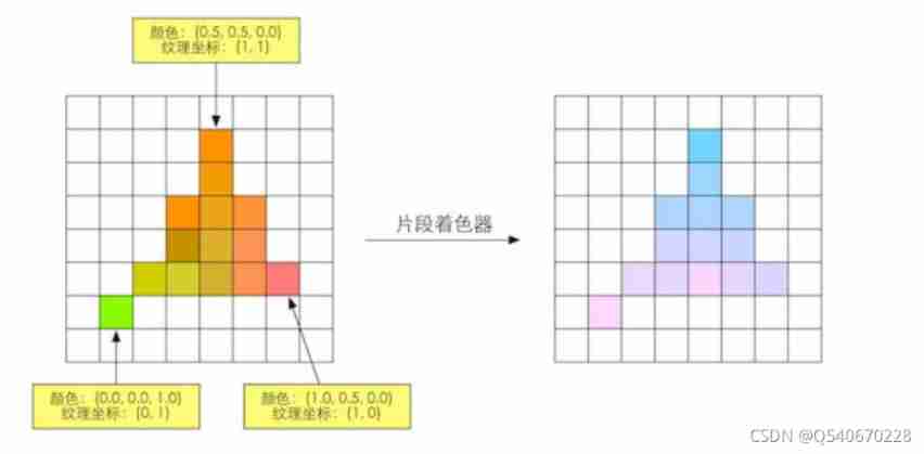
chart 8 Calculate the output color
3-4: Slice by slice operation
This is a OpenGL Chinese saying , stay DirectX in , This stage is called the output merge stage (Output-Merger).
This stage is for each piece fragment To operate , The main tasks are :
① Determine the visibility of each slice , Such as depth test 、 Template testing .
② If a slice passes all tests , Just add the color value of this slice element and the color already stored in the color buffer merger , blend .
This stage is highly configurable , We can set the operation details of each step . At this stage, the first solution is , Every The visibility of slices . This requires a series of tests , Only after passing can it be merged with the color buffer . It doesn't work Pass any one One test , Pieces will be discarded . See the picture (9)
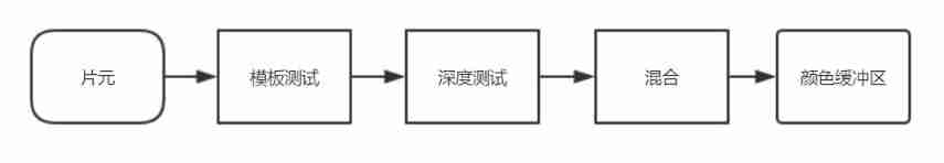
chart 9 Slice testing and merging
The testing process is very complicated , Different interface implementation details are also different , Next, the author will talk about some commonly used tests :
Template testing
Template testing is enabled ,GPU The read mask will be used to read the Template value of slice , Set the value to Compare with the read reference value . This comparison function can be specified by the developer , For example, if it is less than the template value, it will be discarded This piece of yuan or If the value is greater than the template value, discard the slice . Whether the chip passes the template test or not, it can modify the template buffer according to the template test and the following depth test results . This modification is also specified by the developer . Template testing is usually used to limit the area of rendering .
Depth testing
After passing the template test , The chip will be tested in depth . It is also highly configurable .
After opening ,GPU The slice depth value will be compared with the depth value of the existing and depth buffer , This comparison function is also set by the developer . For example, if it is less than the buffer depth value, discard the slice , Or discard the slice when it is greater than or equal to the buffer depth . Usually people prefer to display the object closest to the camera , Therefore, the general comparison function is set to make the current slice depth value smaller than the buffer depth value , The depth value is too large to pass the test . If the chip fails the test , It will be discarded .
Different from template testing , Only after passing can the developer specify whether to overwrite the depth value of the original buffer with the depth value of the slice . This is by opening / Turning off deep writing does .
Merge operation
After passing all the tests , Then comes the merging operation .
The information of each pixel is stored in a place called color buffer , So when performing this rendering , The color buffer often has the result after the last rendering . So we need to merge to make it reach a balanced state .
about Opaque objects , Developers can choose to turn off the hybrid operation . In this way, the color value calculated by the slice shader will directly overwrite the pixel value in the original color buffer .
about Translucent objects , You need to use a blending operation to make this object look transparent .
Mixing operations can also be highly configurable . Started mixing ,GPU Will take out the source color and target color and mix them .
The source color is the color obtained by the slice shader , The target color is the color value that already exists in the color buffer .
Test ahead of time
The purpose of testing in advance is mainly to improve performance
Although logically these tests are performed after the slice shader , But for most GPU Come on , They will try to do these tests before executing the slice shader .
Knowing which pieces will be discarded as early as possible can improve performance , such as unity The depth test in the rendering pipeline of is just before the slice shader . This technique to advance depth testing is called Early-Z technology .
However, if these tests are advanced, their inspection results may conflict with some operations in the slice shader .
thus Unity The general process of rendering pipeline has been introduced ~, This is the first time for the author to write a blog, and the flow chart and explanation are relatively rough , We will continue to write about Unity The content of , I hope it can help you (.^◡^.)
边栏推荐
- [quick start of Digital IC Verification] 26. Ahb-sramc of SystemVerilog project practice (6) (basic points of APB protocol)
- How to release NFT in batches in opensea (rinkeby test network)
- OpenGL common functions
- 避坑:Sql中 in 和not in中有null值的情况说明
- Steps to create P8 certificate and warehousing account
- 连接ftp服务器教程
- 【数字IC验证快速入门】19、SystemVerilog学习之基本语法6(线程内部通信...内含实践练习)
- Cut ffmpeg as needed, and use emscripten to compile and run
- webgl_ Enter the three-dimensional world (2)
- Super signature principle (fully automated super signature) [Yun Xiaoduo]
猜你喜欢
【數字IC驗證快速入門】20、SystemVerilog學習之基本語法7(覆蓋率驅動...內含實踐練習)
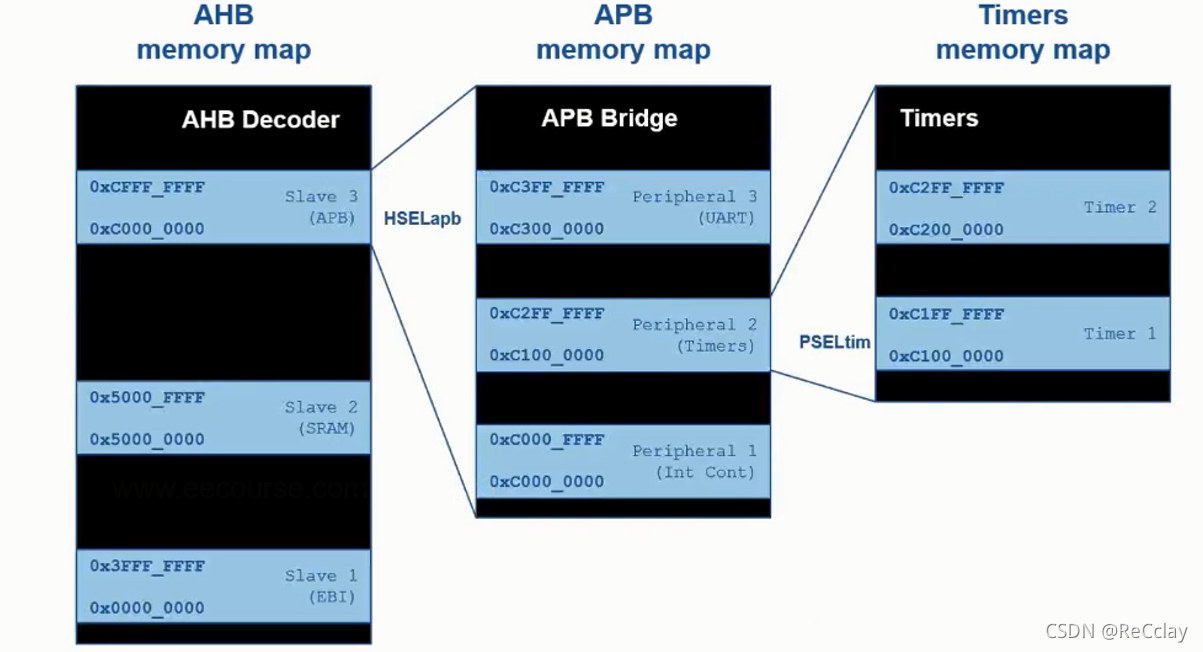
【数字IC验证快速入门】23、SystemVerilog项目实践之AHB-SRAMC(3)(AHB协议基本要点)
![[quick start of Digital IC Verification] 22. Ahb-sramc of SystemVerilog project practice (2) (Introduction to AMBA bus)](/img/3f/40475f9f6e0fcd3f58c93164f65674.png)
[quick start of Digital IC Verification] 22. Ahb-sramc of SystemVerilog project practice (2) (Introduction to AMBA bus)
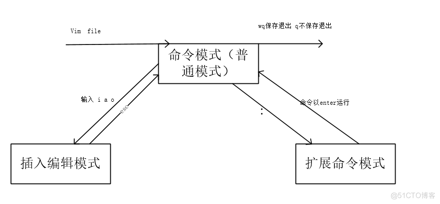
15. Using the text editing tool VIM
![[server data recovery] a case of RAID data recovery of a brand StorageWorks server](/img/aa/6d820d97e82df1d908dc7aa78fc8bf.png)
[server data recovery] a case of RAID data recovery of a brand StorageWorks server
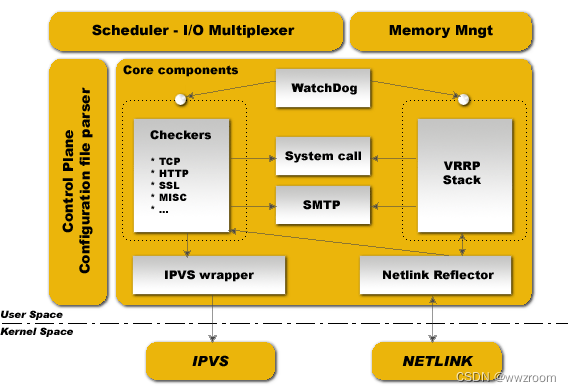
Briefly describe the working principle of kept
unnamed prototyped parameters not allowed when body is present
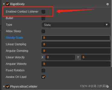
Cocos creator collision and collision callback do not take effect
Wechat applet 01
【數字IC驗證快速入門】26、SystemVerilog項目實踐之AHB-SRAMC(6)(APB協議基本要點)
随机推荐
[quick start of Digital IC Verification] 20. Basic grammar of SystemVerilog learning 7 (coverage driven... Including practical exercises)
Iterator and for of.. loop
Stm32f103c8t6 PWM drive steering gear (sg90)
【微信小程序】Chapter(5):微信小程序基础API接口
Detailed explanation of Cocos creator 2.4.0 rendering process
Qu'est - ce qu'une violation de données
MongoDB数据库基础知识整理
Syntax of generator function (state machine)
Starting from 1.5, build a microservice framework link tracking traceid
HPDC smart base Talent Development Summit essay
[quick start of Digital IC Verification] 26. Ahb-sramc of SystemVerilog project practice (6) (basic points of APB protocol)
Ida Pro reverse tool finds the IP and port of the socket server
Using eating in cocos Creator
Write a ten thousand word long article "CAS spin lock" to send Jay's new album to the top of the hot list
简述keepalived工作原理
[quick start of Digital IC Verification] 23. AHB sramc of SystemVerilog project practice (3) (basic points of AHB protocol)
MySQL bit类型解析
Nacos一致性协议 CP/AP/JRaft/Distro协议
【数字IC验证快速入门】25、SystemVerilog项目实践之AHB-SRAMC(5)(AHB 重点回顾,要点提炼)
2. Basic knowledge of golang