当前位置:网站首页>STM32 summary (HAL Library) - DHT11 temperature sensor (intelligent safety assisted driving system)
STM32 summary (HAL Library) - DHT11 temperature sensor (intelligent safety assisted driving system)
2022-07-05 08:16:00 【IOT Xiaokai】
DHT11 Introduce
DHT11 Digital temperature and humidity sensor is a temperature and humidity composite sensor with calibrated digital signal output , It uses special digital module acquisition technology and temperature and humidity sensing technology , Ensure that the product has high reliability and excellent long-term stability . The sensor consists of a resistive humidity sensor and a NTC Temperature measuring element , And with a high performance 8 Bit single chip microcomputer connected . So this product has excellent quality 、 Super quick response 、 Strong anti-interference ability 、 High cost performance advantages . Every DHT11 Sensors are calibrated in a very accurate humidity calibration room . The calibration factor exists in the form of a program OTP In the memory , These calibration coefficients should be called in the process of detecting the model inside the sensor . Single line serial interface , Make system integration easy and fast . Super small size 、 Very low power consumption , Make it the best choice for even the most demanding applications . Products for 4 Single row pin package , Easy to connect .
DHT11 working principle
2.1、DHT11data data format : ( High first out )
Primary transmission 40 Bit data =8bit Humidity integer data + 8bit Humidity decimal data + 8bit Temperature integer data + 8bit Temperature decimal data + 8bit The checksum . When the data transmission is correct , The checksum data is equal to “8bit Humidity integer data +8 Humidity decimal data +8bit Temperature integer data +8bit Temperature decimal data ” The end of the result 8 position .
user MCU After sending a start signal ,DHT11 Switch from low power consumption to high speed mode , Wait for the end of the host start signal ,DHT11 Send a response signal , Send out 40bit The data of , And trigger a signal acquisition , Users can choose to read some data , From mode ,DHT11 Receive the start signal to trigger a temperature and humidity acquisition , If no start signal is received from the host ,DHT11 Do not actively collect temperature and humidity , After collecting data, switch to low speed mode .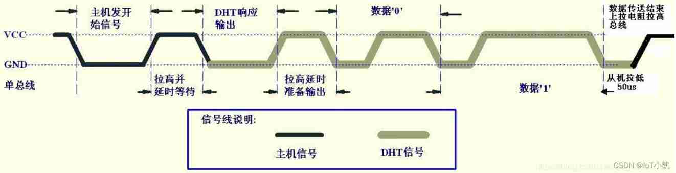
2.2、 Sequential programming
Starting timing
The bus idle state is high , The host pulls down the bus and waits DHT11 Respond to , The host must pull the bus lower than 18 millisecond , Guarantee DHT11 Can detect the start signal .DHT11 After receiving the start signal from the host , Wait for the host start signal to end , And then send 80us Low level response signal . After the host sends the start signal , Delay waiting for 20-40us after , Read DHT11 The response signal , After the host sends the start signal , You can switch to input mode , Or the average output high power can , The bus is pulled up by a pull-up resistor .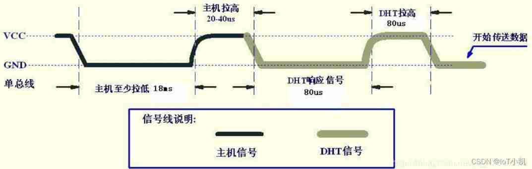
Data receiving timing
The bus is low , explain DHT11 Send a response signal ,DHT11 After sending the response signal , Then pull up the bus 80us, Prepare to send data , each bit All the data are based on 50us The low level slot starts , The length of the high level determines that the data bit is 0 still 1. The format is shown in the figure below . If the read response signal is high , be DHT11 No response , Please check whether the line is connected properly . When the last one bit After the data is transmitted ,DHT11 Pull down the bus 50us, Then, the bus is pulled up by the pull-up resistance and enters the idle state .
Numbers 0 Signal representation 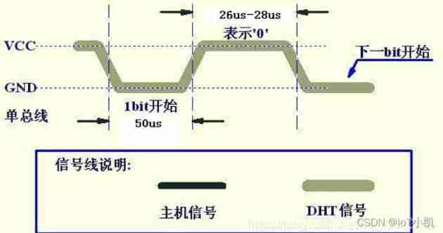
Numbers 1 Signal representation 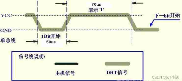
*DHT11 Code
3、DHT11 Communication process and code
3.1、 Simple communication process
Step 1 initialization IO mouth Complete the starting sequence Check DHT11 Whether there is
The signal line of the second host is pulled up to receive data , Receive... In turn 40 position
3.2 The main program part
dht11.c Part of the code *
#include "delay.h"
#include "dht11.h"
#include "tim.h"


#define DHT11_DQ_IN HAL_GPIO_WritePin(GPIOC, DHT11_DATA_OUT_Pin, GPIO_PIN_SET) // Input

// initialization DHT11, At the same time, check whether it is connected DHT11,PA11 initialization

uint8_t DHT11_Init(void)
{

  GPIO_InitTypeDef GPIO_InitStruct = {
    0};

  /* GPIO Ports Clock Enable */
  __HAL_RCC_GPIOC_CLK_ENABLE();


  /*Configure GPIO pin Output Level */
  HAL_GPIO_WritePin(GPIOC, DHT11_DATA_OUT_Pin, GPIO_PIN_SET);

  /*Configure GPIO pin : PtPin */
  GPIO_InitStruct.Pin = DHT11_DATA_OUT_Pin;
  GPIO_InitStruct.Mode = GPIO_MODE_OUTPUT_PP;
  GPIO_InitStruct.Pull = GPIO_PULLDOWN;
  GPIO_InitStruct.Speed = GPIO_SPEED_FREQ_LOW;
  HAL_GPIO_Init(DHT11_DATA_OUT_GPIO_Port, &GPIO_InitStruct);

	DHT11_Rst();
	return DHT11_Check();
}
// Reset DHT11
void DHT11_Rst(void)
{

	DHT11_IO_OUT(); 	//SET OUTPUT
	HAL_GPIO_WritePin(GPIOC, DHT11_DATA_OUT_Pin, GPIO_PIN_RESET); 	// Pull it down
	DelayXms(20);    	// Lower the delay at least 18ms
	HAL_GPIO_WritePin(GPIOC, DHT11_DATA_OUT_Pin, GPIO_PIN_SET); 	//DQ=1, pull up
	DelayUs(30);     	// Raise the delay at least 20~40us
}

// Test response
// return 1: Detect errors
// return 0: Test successful
uint8_t DHT11_Check(void)
{

	uint8_t retry=0;
	DHT11_IO_IN();//SET INPUT
    while (HAL_GPIO_ReadPin(GPIOC, GPIO_PIN_0)&&retry<100)//DHT11 Pull it down 40~80us
	{

		retry++;
		DelayUs(1);
	};
	if(retry>=100)return 1;
	else retry=0;
    while (!HAL_GPIO_ReadPin(GPIOC, GPIO_PIN_0)&&retry<100)//DHT11 Pull up again 40~80us
	{

		retry++;
		DelayUs(1);
	};
	if(retry>=100)return 1;
	return 0;
}

// Read a bit Bit
// return 1 or 0
uint8_t DHT11_Read_Bit(void)
{

 	uint8_t retry=0;
	while(HAL_GPIO_ReadPin(GPIOC, GPIO_PIN_0)&&retry<100)// Wait for low level
	{

		retry++;
		DelayUs(1);
	}
	retry=0;
	while(!HAL_GPIO_ReadPin(GPIOC, GPIO_PIN_0)&&retry<100)// Wait for high level
	{

		retry++;
		DelayUs(1);
	}
	DelayUs(40);// wait for 40us
	if(HAL_GPIO_ReadPin(GPIOC, GPIO_PIN_0))return 1;
	else return 0;
}

// Read a byte
// Returns the data read
uint8_t DHT11_Read_Byte(void)
{

	uint8_t i,dat;
	dat=0;
	for (i=0;i<8;i++)
	{

		dat<<=1;
		dat|=DHT11_Read_Bit();
	}
	return dat;
}

//DHT11 Read data once
//temp: temperature ( Range :0~50°)
//humi: humidity ( Range :20%~90%)
//tem: Temperature decimal places
//hum: Humidity decimal places
uint8_t DHT11_Read_Data(uint8_t *temp,uint8_t *humi,uint8_t *tem,uint8_t *hum)
{

 	uint8_t buf[5];
	uint8_t i;
	DHT11_Rst();
	if(DHT11_Check()==0)
	{

		for(i=0;i<5;i++)// Read 40 Bit byte
		{

			buf[i]=DHT11_Read_Byte();
		}
		if((buf[0]+buf[1]+buf[2]+buf[3])==buf[4])
		{

			*humi=buf[0];
			*hum=buf[1];
			*temp=buf[2];
			*tem=buf[3];
		}
	}
	else return 1;
	return 0;
}


//DHT11 Output mode configuration
void DHT11_IO_OUT()
{

  GPIO_InitTypeDef GPIO_InitStruct = {
    0};

  /* GPIO Ports Clock Enable */
  __HAL_RCC_GPIOC_CLK_ENABLE();


  /*Configure GPIO pin Output Level */
  HAL_GPIO_WritePin(GPIOC, DHT11_DATA_OUT_Pin, GPIO_PIN_SET);

  /*Configure GPIO pin : PtPin */
  GPIO_InitStruct.Pin = DHT11_DATA_OUT_Pin;
  GPIO_InitStruct.Mode = GPIO_MODE_OUTPUT_PP;
  GPIO_InitStruct.Pull = GPIO_PULLDOWN;
  GPIO_InitStruct.Speed = GPIO_SPEED_FREQ_LOW;
  HAL_GPIO_Init(DHT11_DATA_OUT_GPIO_Port, &GPIO_InitStruct);
}

//DHT11 Input mode configuration
void DHT11_IO_IN(void)
{

  GPIO_InitTypeDef GPIO_InitStruct = {
    0};

  /* GPIO Ports Clock Enable */
  __HAL_RCC_GPIOC_CLK_ENABLE();
  /*Configure GPIO pin : PC0 */
  GPIO_InitStruct.Pin = GPIO_PIN_0;
  GPIO_InitStruct.Mode = GPIO_MODE_INPUT;
  GPIO_InitStruct.Pull = GPIO_PULLUP;
  HAL_GPIO_Init(GPIOC, &GPIO_InitStruct);
}
dht11.h Part of the code

```c
#ifndef _DHT11_H_
#define _DHT11_H_
#include "main.h"
#define DHT11_DATA_OUT_Pin GPIO_PIN_0
#define DHT11_DATA_OUT_GPIO_Port GPIOC

void DHT11_Rst(void);
uint8_t DHT11_Check(void);
uint8_t DHT11_Read_Bit(void);
uint8_t DHT11_Read_Byte(void);
uint8_t DHT11_Read_Data(uint8_t *temp,uint8_t *humi,uint8_t *tem,uint8_t *hum);
uint8_t DHT11_Init(void);
void DHT11_IO_IN(void);
void DHT11_IO_OUT();
#endif
mian.c Code
```c
/* USER CODE BEGIN Header */
/**
******************************************************************************
* @file : main.c
* @brief : Main program body
******************************************************************************
* @attention
*
* <h2><center>© Copyright (c) 2022 STMicroelectronics.
* All rights reserved.</center></h2>
*
* This software component is licensed by ST under BSD 3-Clause license,
* the "License"; You may not use this file except in compliance with the
* License. You may obtain a copy of the License at:
* opensource.org/licenses/BSD-3-Clause
*
******************************************************************************
*/
/* USER CODE END Header */
/* Includes ------------------------------------------------------------------*/
#include "main.h"
#include "tim.h"
#include "usart.h"
#include "gpio.h"
/* Private includes ----------------------------------------------------------*/
/* USER CODE BEGIN Includes */
#include "dht11.h"
#include "delay.h"
/* USER CODE END Includes */
/* Private typedef -----------------------------------------------------------*/
/* USER CODE BEGIN PTD */
/* USER CODE END PTD */
/* Private define ------------------------------------------------------------*/
/* USER CODE BEGIN PD */
/* USER CODE END PD */
/* Private macro -------------------------------------------------------------*/
/* USER CODE BEGIN PM */
/* USER CODE END PM */
/* Private variables ---------------------------------------------------------*/
/* USER CODE BEGIN PV */
/* USER CODE END PV */
/* Private function prototypes -----------------------------------------------*/
void SystemClock_Config(void);
/* USER CODE BEGIN PFP */
/* USER CODE END PFP */
/* Private user code ---------------------------------------------------------*/
/* USER CODE BEGIN 0 */
/* USER CODE END 0 */
/**
* @brief The application entry point.
* @retval int
*/
int main(void)
{
/* USER CODE BEGIN 1 */
/* USER CODE END 1 */
/* MCU Configuration--------------------------------------------------------*/
/* Reset of all peripherals, Initializes the Flash interface and the Systick. */
HAL_Init();
/* USER CODE BEGIN Init */
/* USER CODE END Init */
/* Configure the system clock */
SystemClock_Config();
/* USER CODE BEGIN SysInit */
/* USER CODE END SysInit */
/* Initialize all configured peripherals */
MX_GPIO_Init();
MX_TIM6_Init();
MX_TIM7_Init();
MX_USART1_UART_Init();
MX_USART2_UART_Init();
MX_USART3_UART_Init();
/* USER CODE BEGIN 2 */
Delay_Init();
uint8_t temperature;
uint8_t humidity;
uint8_t temp;
uint8_t humi;
uint8_t rx_buf[5];
DHT11_Init(); //DHT11 initialization Pin PA4PA6-MISO PA7-MOSI
/* USER CODE END 2 */
/* Infinite loop */
/* USER CODE BEGIN WHILE */
while (1)
{
/* USER CODE END WHILE */
/* USER CODE BEGIN 3 */
DHT11_Read_Data(&temperature,&humidity,&temp,&humi);
rx_buf[0]=temperature;
rx_buf[1]=humidity;
printf("temp=%d,humi=%d\r\n",rx_buf[0],rx_buf[1]);
DelayXms(5000);
}
/* USER CODE END 3 */
}
/**
* @brief System Clock Configuration
* @retval None
*/
void SystemClock_Config(void)
{
RCC_OscInitTypeDef RCC_OscInitStruct = {0};
RCC_ClkInitTypeDef RCC_ClkInitStruct = {0};
/** Initializes the RCC Oscillators according to the specified parameters
* in the RCC_OscInitTypeDef structure.
*/
RCC_OscInitStruct.OscillatorType = RCC_OSCILLATORTYPE_HSE;
RCC_OscInitStruct.HSEState = RCC_HSE_ON;
RCC_OscInitStruct.HSEPredivValue = RCC_HSE_PREDIV_DIV1;
RCC_OscInitStruct.HSIState = RCC_HSI_ON;
RCC_OscInitStruct.PLL.PLLState = RCC_PLL_ON;
RCC_OscInitStruct.PLL.PLLSource = RCC_PLLSOURCE_HSE;
RCC_OscInitStruct.PLL.PLLMUL = RCC_PLL_MUL9;
if (HAL_RCC_OscConfig(&RCC_OscInitStruct) != HAL_OK)
{
Error_Handler();
}
/** Initializes the CPU, AHB and APB buses clocks
*/
RCC_ClkInitStruct.ClockType = RCC_CLOCKTYPE_HCLK|RCC_CLOCKTYPE_SYSCLK
|RCC_CLOCKTYPE_PCLK1|RCC_CLOCKTYPE_PCLK2;
RCC_ClkInitStruct.SYSCLKSource = RCC_SYSCLKSOURCE_PLLCLK;
RCC_ClkInitStruct.AHBCLKDivider = RCC_SYSCLK_DIV1;
RCC_ClkInitStruct.APB1CLKDivider = RCC_HCLK_DIV2;
RCC_ClkInitStruct.APB2CLKDivider = RCC_HCLK_DIV1;
if (HAL_RCC_ClockConfig(&RCC_ClkInitStruct, FLASH_LATENCY_2) != HAL_OK)
{
Error_Handler();
}
}
/* USER CODE BEGIN 4 */
/* USER CODE END 4 */
/**
* @brief This function is executed in case of error occurrence.
* @retval None
*/
void Error_Handler(void)
{
/* USER CODE BEGIN Error_Handler_Debug */
/* User can add his own implementation to report the HAL error return state */
__disable_irq();
while (1)
{
}
/* USER CODE END Error_Handler_Debug */
}
#ifdef USE_FULL_ASSERT
/**
* @brief Reports the name of the source file and the source line number
* where the assert_param error has occurred.
* @param file: pointer to the source file name
* @param line: assert_param error line source number
* @retval None
*/
void assert_failed(uint8_t *file, uint32_t line)
{
/* USER CODE BEGIN 6 */
/* User can add his own implementation to report the file name and line number,
ex: printf("Wrong parameters value: file %s on line %d\r\n", file, line) */
/* USER CODE END 6 */
}
#endif /* USE_FULL_ASSERT */
/************************ (C) COPYRIGHT STMicroelectronics *****END OF FILE****/
File download link address
Reference documents
边栏推荐
- Management and use of DokuWiki (supplementary)
- Measurement fitting based on Halcon learning [III] PM_ measure_ board. Hdev routine
- Embedded composition and route
- 实例005:三数排序 输入三个整数x,y,z,请把这三个数由小到大输出。
- Volatile of C language
- Anonymous structure in C language
- Talk about the circuit use of TVs tube
- Soem EtherCAT source code analysis attachment 1 (establishment of communication operation environment)
- matlab timeserise
- Circleq of linked list
猜你喜欢
Charge pump boost principle - this article will give you a simple understanding
![Shape template matching based on Halcon learning [viii] PM_ multiple_ models. Hdev routine](/img/13/22a1915329f58acd54c40176f6f301.jpg)
Shape template matching based on Halcon learning [viii] PM_ multiple_ models. Hdev routine
Development tools -- gcc compiler usage
FIO测试硬盘性能参数和实例详细总结(附源码)
Shell script
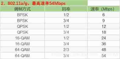
Wifi-802.11 negotiation rate table
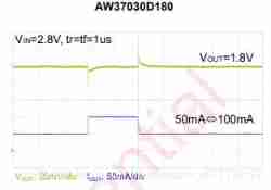
Several important parameters of LDO circuit design and type selection
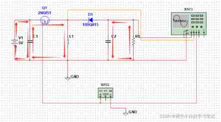
Negative pressure generation of buck-boost circuit

Matlab2018b problem solving when installing embedded coder support package for stmicroelectronic
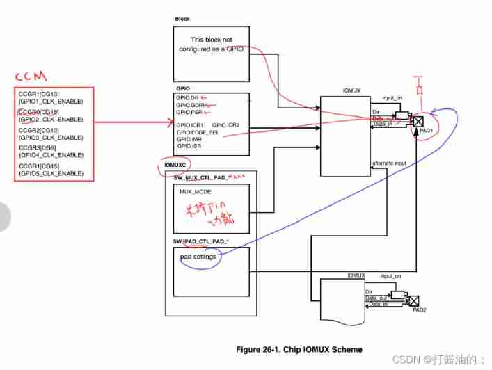
Drive LED -- GPIO control
随机推荐
Some thoughts on extracting perspectives from ealfa and Ebeta
STM32 --- GPIO configuration & GPIO related library functions
C # joint configuration with Halcon
Bootloader implementation of PIC MCU
Weidongshan Internet of things learning lesson 1
Problem solving: interpreter error: no file or directory
Shape template matching based on Halcon learning [vi] find_ mirror_ dies. Hdev routine
STM32 tutorial triple ADC interleaved sampling
FIO测试硬盘性能参数和实例详细总结(附源码)
Wifi-802.11 negotiation rate table
Classic application of MOS transistor circuit design (1) -iic bidirectional level shift
Stm32--- systick timer
实例006:斐波那契数列
Reasons for rapid wear of conductive slip rings
C language enhancement -- pointer
Basic embedded concepts
Management and use of DokuWiki
Halcon's practice based on shape template matching [2]
Sizeof (function name) =?
Communication standard -- communication protocol