当前位置:网站首页>MCU realizes OTA online upgrade process through UART
MCU realizes OTA online upgrade process through UART
2022-07-06 00:41:00 【strongerHuang】
Focus on + Star sign public Number , Don't miss the highlights

Material source | The Internet
OTA Upgrading is nothing new , Now most IOT terminal devices , Basically have this function .
Today with AT32 As an example, let me share with you OTA The detailed process of upgrading .
summary
Over the air technology OTA(Over-the-Air Technology) Is the user's own program in the process of running User Flash Part of the area to burn , The purpose is to conveniently pass through the reserved communication port after the product is released , Update and upgrade the firmware program in the product . Usually achieve OTA When the function , That is to say, the user program updates itself during operation , You need to write two project codes when you design the firmware program , The first program is Bootloader Area , Second project procedure App The code is the real function code , Perform applications and upgrades . These two parts of project code are burned at the same time User Flash in .
chart 1. OTA Code execution process
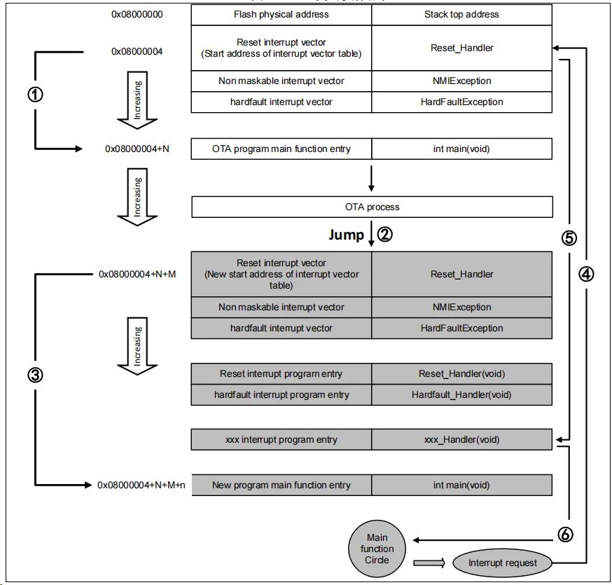
In the process shown above ,MCU After reset , from 0x08000004 Address take out the address of reset interrupt vector , And jump to reset interrupt service program , After running the reset interrupt service program, jump to Bootloader Of main function , As shown in the figure ① Shown ; The execution of the Bootloader in the future (App The code is in the figure FLASH Gray bottom part App The starting address of the reset interrupt vector of the program is 0x08000004+N+M), Jump to App Reset vector table of program , Take out App The address of the reset interrupt vector of the program , And jump to execution App Program reset interrupt service program , Then jump to App programmatic main function , As shown in the figure ② and ③ Shown , Again main The function is a loop , And notice that at this point AT32 Of FLASH, In different places , There are two interrupt vector tables .
stay main During function execution , If CPU Get an interrupt request ,PC Pointer is still forced to jump to address 0x08000004 At the interrupt vector table , instead of App Interrupt vector table of program , As shown in the figure ④ Shown ; Program according to our set interrupt vector table offset , Jump to the new interrupt service program corresponding to the interrupt source , As shown in the figure ⑤ Shown ; After executing the interrupt service program , Program return main The function continues to run , As shown in the figure ⑥ Shown .
Through the analysis of the above two processes , We know OTA The program must meet two requirements :
1) App The procedure must be in Bootloader Some offset after the program is x The address begins .
2) Must be App The interrupt vector table of the program moves accordingly , The offset of the movement is x.
AT32 USART OTA Quick ways to use
Hardware resources
Is used in the document AT-START-AT32F403A Take the hardware condition of the experimental board as an example ,OTA demo The source code also includes AT32 Other models , Users only need to compile the corresponding model project and burn it in AT-START Just run the test board .
1) Indicator light LED2/LED3/LED4
2) USART1(PA9/PA10)
3) AT-START Experiment board
Software resources
1) tool_release
● IAP_Programmer.exe,PC machine tool, For demonstration OTA Upgrade process
2) source_code
● Bootloader,Bootloader Source program , function LED2 flashing
● App_led3_toggle,App1 Source program , function LED3 flashing
● App_led4_toggle,App2 Source program , function LED4 flashing
notes : The project is based on keil v5 establish , If the user needs to use on other compilation environments , Please refer to the corresponding BSP Catalog AT32F403A_407_Firmware_Library_V2.x.x\project\at_start_f403a\templates Various compilation environments in ( for example IAR6/7/8,keil 4/5,eclipse_gcc) Make corresponding modifications .
OTA Demo Use
This document describes two commonly used OTA application demo,template app and dual app, Later chapters will introduce .
1) open Bootloader Engineering source program , Select the corresponding MCU Model number target Download to the experimental board after compilation
2) open IAP_Programmer.exe
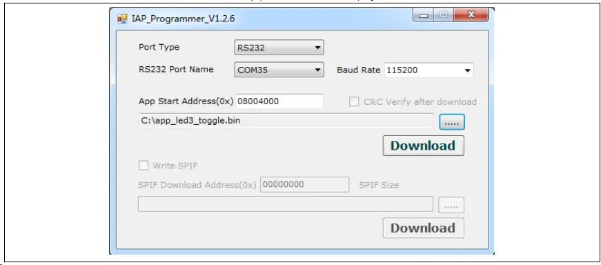
3) Choose the right serial port 、APP Download address and bin file , Click on Download download , Here's the picture
4) Observe LED2/3/4 flashing ,LED2 flashing -Bootloader Work ,LED3 flashing -App1 Work ,LED4 flashing -App2 Work
chart 2. IAP demo Upper computer
Template app OTA Program settings
Address distribution
chart 3. Flash Address assignment
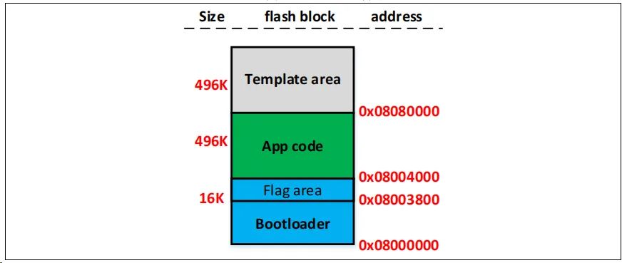
notes :Bootloader The last sector of the region , Used to store and prevent errors in the upgrade process ( Power failure and other abnormal conditions ) Of flag, Users compile and modify Bootloader when , Make sure not to cover flag The address of .
Execute the process
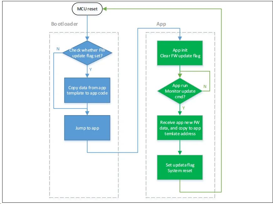
OTA It is divided into Bootloader、App and Template In the third part of , Apply to App In the implementation of ,Template As new only App Temporary storage space for firmware data . The overall flow chart of program execution is as follows :
chart 4. Program execution flow
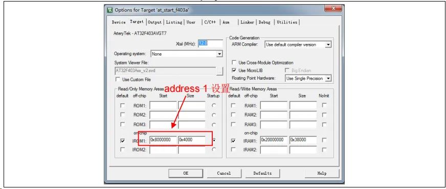
Bootloader project Set up
1) Keil Set up
chart 5. Bootloader project in address 1 stay Keil Set up
2) Bootloader Source program modification ota.h In file
chart 6. Bootloader project in address 2 Set... In the program

App project Set up
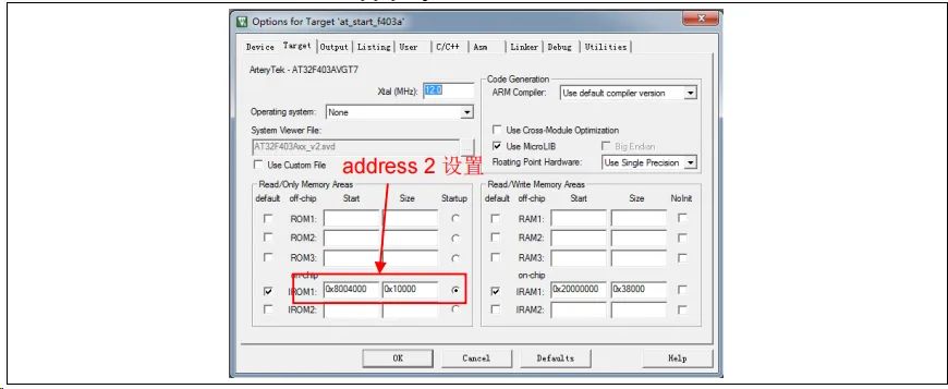
OTA demo Provides 2 individual App The program is for testing , All with address 2(0x800 4000) Is the starting address .App1 LED3 flashing ,App2 LED4 flashing . With App1 For example , The design steps are as follows :
1) Keil Engineering setup
chart 7. App project in address 2 stay Keil Set up
2) App1 Source program settings
chart 8. App project The vector table offset is set in the program

3) Compile the generated bin file
adopt User tab , Set call after compilation fromelf.exe, according to .axf File generation .bin file , be used for OTA to update . Through the above 3 A step , We can get one .bin Of APP Program , adopt Bootloader The program can be updated .
4) Turn on debug app code function
If you're designing App code In the process, we need to App project Conduct separate debugging , Please follow the steps below .
● To download Bootloader engineering
● Re commissioning App engineering
Dual app OTA And program settings
Address distribution
chart 9. Flash Address assignment

notes :Bootloader At the end of the zone 2 Sectors , To hold App Is it normal flag, Users compile and modify Bootloader when , Make sure not to cover flag The address of .
Execute the process
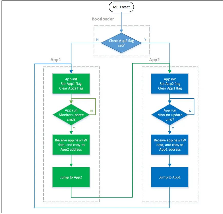
OTA It is divided into Bootloader、App1 and App2 In the third part of , Apply to App1 or App2 In the implementation of . The overall flow chart of program execution is as follows :
chart 10. Program execution flow
Bootloader project Set up
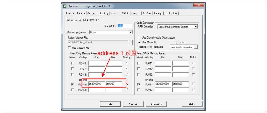
3) Keil Set up
chart 11. Bootloader project in address 1 stay Keil Set up
4) Bootloader Source program modification ota.h In file
chart 12. Bootloader project in address 2 Set... In the program

App project Set up
OTA demo Provides 2 individual App The program is for testing ,app_led3_toggle With 0x800 4000 Is the starting address ,app_led4_toggle With 0x8080000 Is the starting address .App1 LED3 flashing ,App2 LED4 flashing . With App1 For example , The design steps are as follows :
5) Keil Engineering setup
chart 13. App project in address 2 stay Keil Set up
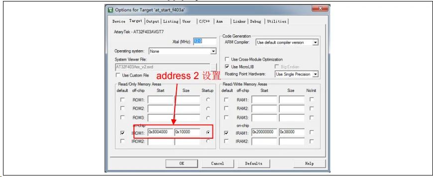
6) App1 Source program settings
chart 14. App project The vector table offset is set in the program

7) Compile the generated bin file
adopt User tab , Set call after compilation fromelf.exe, according to .axf File generation .bin file , be used for OTA to update . Through the above 3 A step , We can get one .bin Of APP Program , adopt Bootloader The program can be updated .
8) Turn on debug App code function
If you're designing App code In the process, we need to App project Conduct separate debugging , Please follow the steps below .
● To download Bootloader engineering
● Re commissioning App engineering
Bootloader/App Serial communication protocol with upper computer
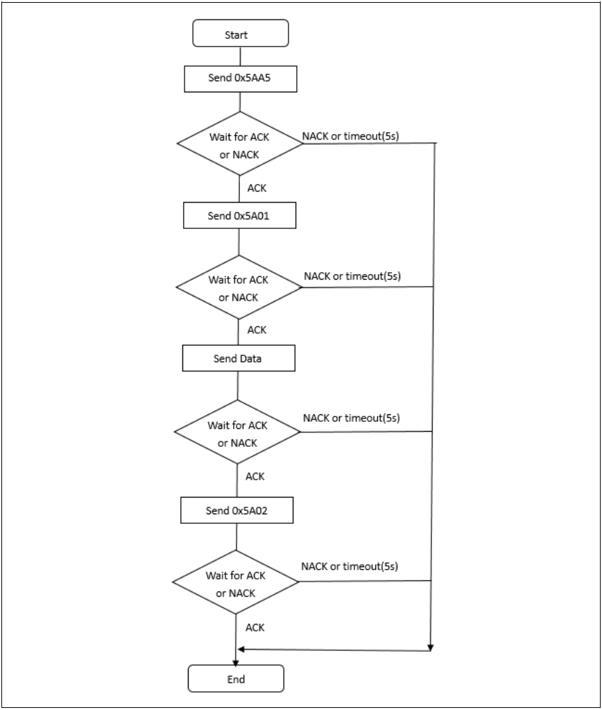
The program communicates with the upper computer , Receive firmware upgrade data , The communication protocols between the upper computer and the embedded end are as follows :
1) Upper computer communication protocol
chart 15. Upper computer communication protocol
2) Embedded end lower computer communication protocol
chart 16. Lower computer communication protocol
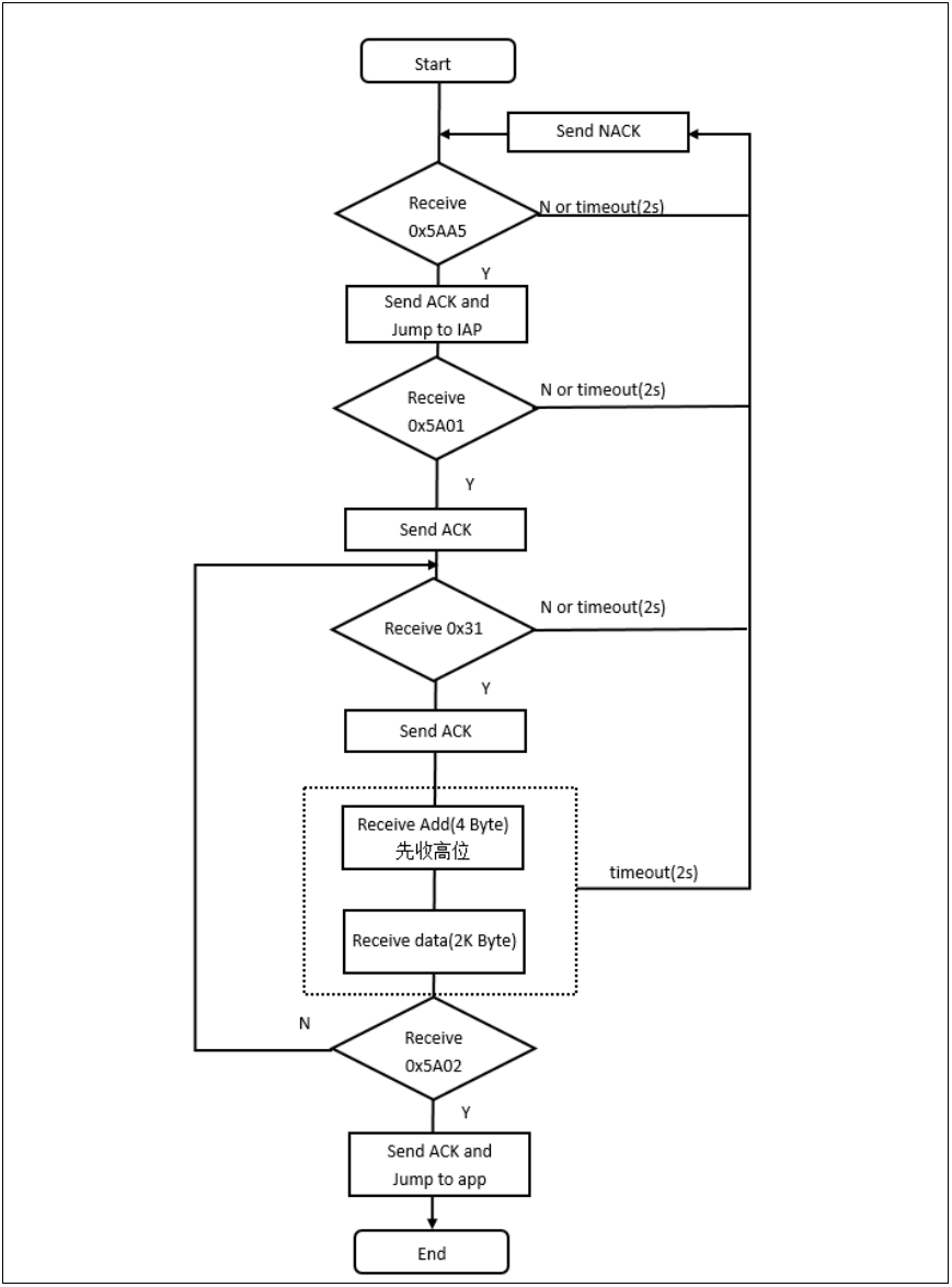
notes :ACK:0xCCDD
NACK:0xEEFF
Data:0x31+Addr+ data +chenksum(1byte)
Addr:4bytes, High in the former
Kbytes, Download data , Insufficient 2K Content filling 0xFF
Checksum:1byte,4bytes Of Addr+2KBytes The lower eight bits of the checksum of the data
------------ END ------------

● special column 《 Embedded tools 》
● special column 《 Embedded development 》
● special column 《Keil course 》
● Embedded column selection tutorial
Pay attention to the reply of the official account “ Add group ” Join the technical exchange group according to the rules , reply “1024” See more .

Click on “ Read the original ” See more sharing .
边栏推荐
- [groovy] compile time meta programming (AST syntax tree conversion with annotations | define annotations and use groovyasttransformationclass to indicate ast conversion interface | ast conversion inte
- [groovy] XML serialization (use markupbuilder to generate XML data | set XML tag content | set XML tag attributes)
- Uniapp development, packaged as H5 and deployed to the server
- Spark AQE
- For a deadline, the IT fellow graduated from Tsinghua suddenly died on the toilet
- 可恢复保险丝特性测试
- notepad++正则表达式替换字符串
- Global and Chinese markets for hinged watertight doors 2022-2028: Research Report on technology, participants, trends, market size and share
- Idea远程提交spark任务到yarn集群
- [groovy] compile time metaprogramming (compile time method injection | method injection using buildfromspec, buildfromstring, buildfromcode)
猜你喜欢

从 1.5 开始搭建一个微服务框架——调用链追踪 traceId
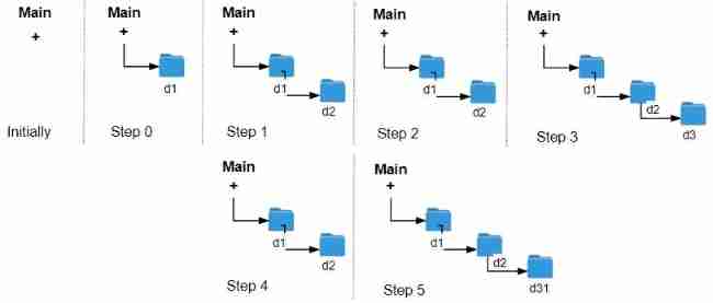
LeetCode 1598. Folder operation log collector
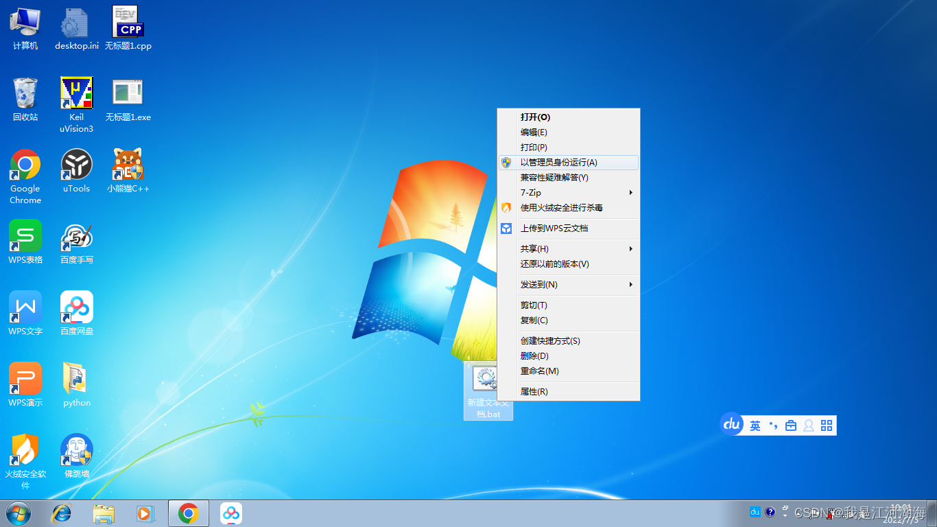
About the slmgr command
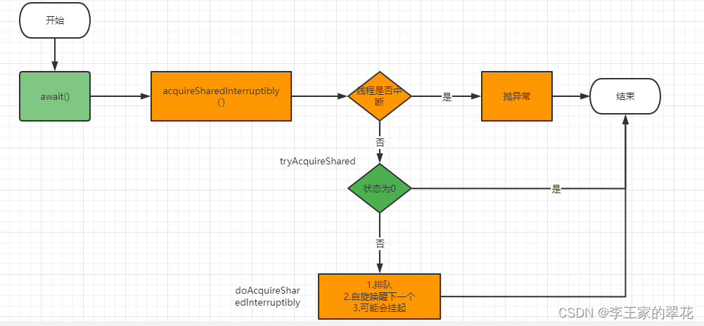
Multithreading and high concurrency (8) -- summarize AQS shared lock from countdownlatch (punch in for the third anniversary)
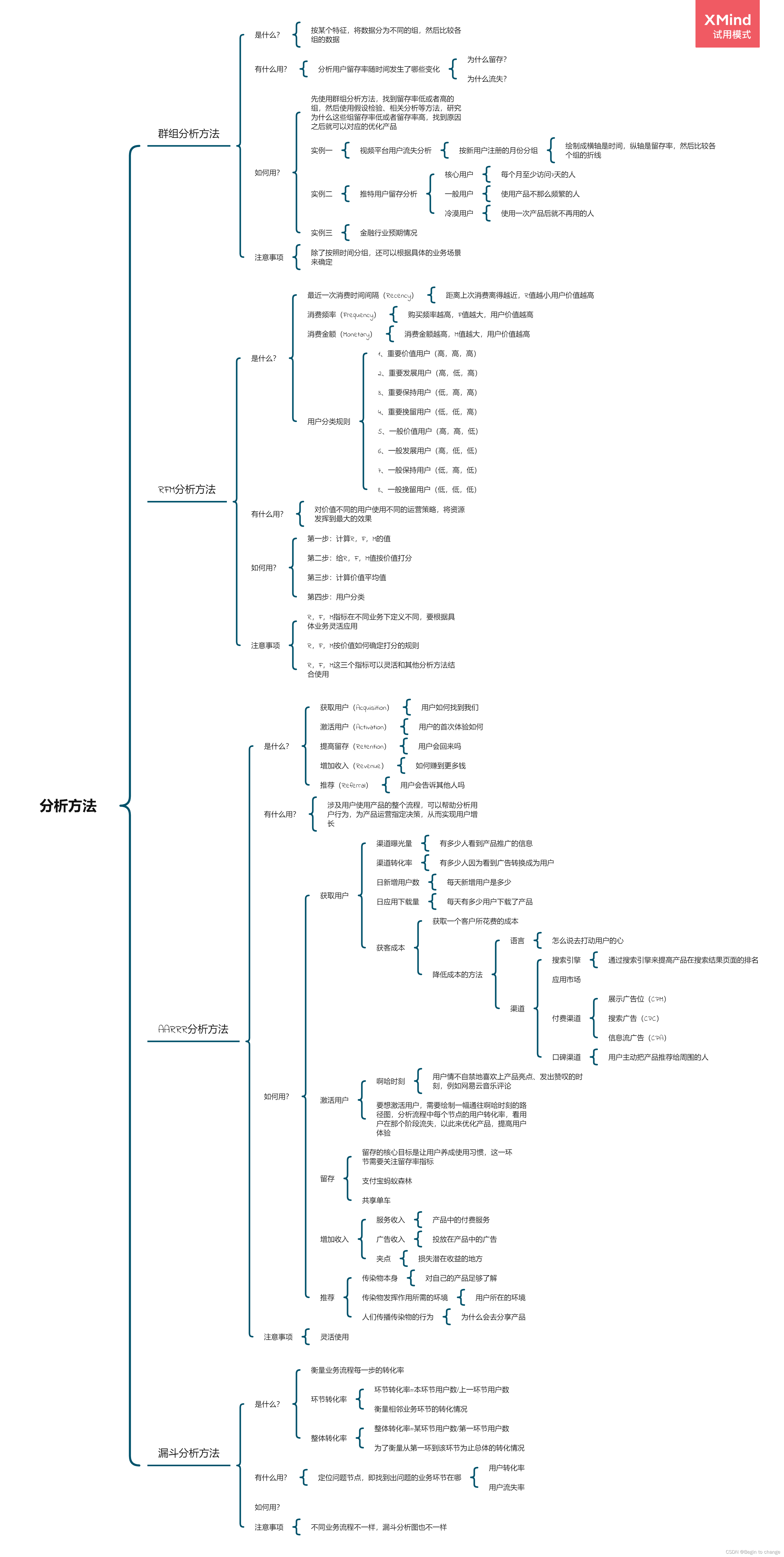
Data analysis thinking analysis methods and business knowledge - analysis methods (III)
Location based mobile terminal network video exploration app system documents + foreign language translation and original text + guidance records (8 weeks) + PPT + review + project source code
Extracting profile data from profile measurement
Room cannot create an SQLite connection to verify the queries
如何制作自己的機器人
Leetcode:20220213 week race (less bugs, top 10% 555)
随机推荐
Meta AI西雅图研究负责人Luke Zettlemoyer | 万亿参数后,大模型会持续增长吗?
Spark SQL null value, Nan judgment and processing
Extension and application of timestamp
Spark-SQL UDF函数
STM32 key chattering elimination - entry state machine thinking
devkit入门
Go learning - dependency injection
Notepad++ regular expression replacement string
Idea remotely submits spark tasks to the yarn cluster
LeetCode 8. String conversion integer (ATOI)
LeetCode 斐波那契序列
Recognize the small experiment of extracting and displaying Mel spectrum (observe the difference between different y_axis and x_axis)
STM32 configuration after chip replacement and possible errors
The global and Chinese markets of dial indicator calipers 2022-2028: Research Report on technology, participants, trends, market size and share
Uniapp development, packaged as H5 and deployed to the server
Solve the problem of reading Chinese garbled code in sqlserver connection database
PHP determines whether an array contains the value of another array
LeetCode 1189. Maximum number of "balloons"
Classical concurrency problem: the dining problem of philosophers
Location based mobile terminal network video exploration app system documents + foreign language translation and original text + guidance records (8 weeks) + PPT + review + project source code