当前位置:网站首页>Superscalar processor design yaoyongbin Chapter 8 instruction emission excerpt
Superscalar processor design yaoyongbin Chapter 8 instruction emission excerpt
2022-07-07 11:52:00 【Qi Qi】
8.1 summary
What is launch ? It is to send instructions that meet certain conditions from the transmission queue issue queue Choose from , And send it to FU The process of execution in . The transmit queue page can be called a reservation station reservation station.
The launch queue will follow certain rules , Select the instructions for which the source operands are ready , Send it to FU In the implementation of , This process is called launch .
But for superscalar processors that execute out of order , Only a few instructions , for example store Instructions and branch instructions , Will use this method of sequential execution , And for most instructions , Are launched in a disorderly manner , The design is more difficult .
After the command arrives in the transmission queue , It will no longer flow in the processor in the order specified in the program , As long as the operands of an instruction in the transmission queue are ready , And meet the launch conditions , You can send it to the corresponding FU To perform .
The function of the transmit queue is to use the hardware to save a certain number of instructions , Then find the executable instructions from these instructions , Regardless of the original order between instructions , This is the disordered execution of instructions .
In the pipeline of superscalar processors , The hardware in the launch phase is complex , Generally, its timing is on the critical path of the processor , It directly affects the cycle time of the processor .
After the launch phase , All instructions are executed out of order , Until the final submission of the assembly line commit Stage , Just use reordering ROB Pull these instructions back to the original order specified in the program .
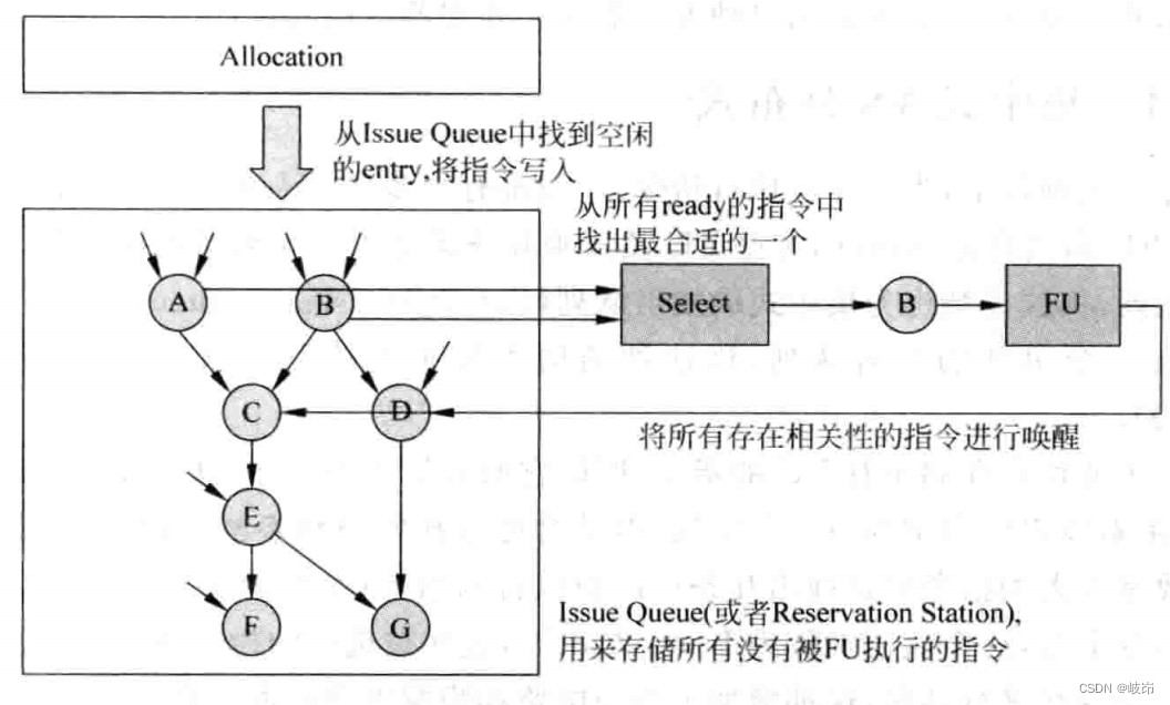
The execution process of pipeline launch stage , Some important parts involved :
(1) Launch queue , Used to store that has been renamed by the register , But it was not delivered FU Instructions executed , It is also often called a reservation station .
(2) Distribution circuit , Used to find free space from the transmission queue , Store the instruction after renaming the register , Design methods of different transmission queues , Will directly affect the realization of this part of the circuit .
(3) Select the circuit , Also called arbitration arbiter circuit , If there are multiple instructions in the transmit queue, the operands are ready , Then this circuit will follow certain rules , Find the most suitable instruction , Deliver to FU To perform , This part is the circuit, which is the key part in the launch stage , It will directly affect the execution efficiency of the whole processor .
(4) Wake up circuit , When an instruction passes FU Execute to get the result operand , It will notify all instructions waiting for this data in the transmission queue , The corresponding source register in these instructions will be set to a valid state , Even if this process wakes up . If all source operands of an instruction in the transmit queue are valid , Then this instruction is in the ready state , You can apply to the selection circuit .
Stored in the transmission queue A-G These seven instructions , Instructions A And instructions B Are already in a state of readiness , After the arbitration of the selection circuit , Select the command B Deliver to FU In the process of operation , When it is finished , Will neutralize the transmission queue B All source registers with the same result register of the instruction ( Located in instruction C and D) Also set as valid , This wakes up the relevant instructions .
There are many ways to realize the launch phase , The launch queue at the center of this stage , Its implementation mode directly determines the implementation mode of the whole launch stage , It can be designed as an integrated centralized, You can also design the composition cloth distribute; It can be set to compress compressing, Or uncompressed non-compressing; It can be designed as data capture data-capture, It can also be designed as non data capture non-data-capture. These structures are orthogonal , They can be combined with each other .
8.1.1 Centralized VS Distributed
In superscalar processors , To execute instructions in parallel , There are usually many FU, For example, some FU Responsible for integer addition and subtraction , Some are responsible for memory access , Some are responsible for multiplication and division . If all these FU All share a transmission queue , This structure is called centralized transmission queue CIQ; And if each FU There is a separate transmission queue , Then it is distributed transmission queue DIQ.
CIQ Because I am responsible for storing all FU Instructions , So its capacity needs to be very large , Design has great utilization efficiency , Do not waste every space in the transmission queue , But it will make the selection circuit and wake-up circuit more complex , Because it is necessary to select several instructions that can be executed from a large number of instructions ( The number selection depends on the maximum number of instructions that can be executed simultaneously in each cycle , This value is often called issue width), These selected instructions also need to wake up all relevant instructions in the transmission queue , This increases the area and delay of the selection circuit and wake-up circuit .
DIQ For every one FU Are equipped with a transmission queue , So the capacity of each transmission queue can be very small , This greatly simplifies the design of the selection circuit . But when a transmission queue is full , Even if there is space in other transmission queues , You cannot continue to write new instructions to it , At this point, all pipelines before the launch phase need to be suspended , Until the launch queue is free . This leads to low utilization efficiency of the transmission queue , And because its distribution is relatively scattered , The wiring complexity required for wake-up operation also increases .
Modern processors generally use a combination of the above two methods , Make some FU Use a transmission queue together , Specifically, those FU Share a transmission queue , Yes and instruction set 、 Design goals and other related , This is the content of processor architecture design .
8.1.2 Data capture VS Non data capture
Read the value of the register at that stage of the pipeline , It directly determines the design of other components in the processor . Generally speaking , There are two time points for reading registers :
(1) Read registers before the launch phase of the pipeline , Also known as data capture . Instructions renamed by registers will first read the physical register heap , Then write the read value to the transmit queue along with the instruction . If the value of some registers has not been calculated , Then the number of the register will be written to the transmission queue , For the wake-up process . It will be marked as currently unavailable , These registers will get their values through the bypass network at a later time , No longer need to access the physical register heap . In the launch queue , The place where instruction operands are stored is called playload RAM.
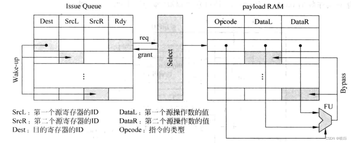
stay payload RAM Stores the value of the instruction source operand , When the instruction is selected by the arbitration circuit from the transmission queue , You can directly from payload RAM Read the source operand at the corresponding place in , And send it to FU In the implementation of .
When an instruction is selected from the transmit queue , It will broadcast the number value of the destination register , Other instructions in the transmit queue will compare their source register number with the number value of this broadcast , Once the same situation is found , It's in payload RAM Mark the corresponding position , When the selected command is FU When the calculation in , Will write its results to payload RAM These corresponding positions , This is achieved through the bypass network . This way is like payload Catching FU Calculation of calculation , So it is called data capture , The transmit queue is responsible for comparing whether the register number values are equal , and payload RAM Responsible for storing source operands , And capture the corresponding FU Result .
In superscalar processors , use machine width To mark the actual number of instructions that can be decoded and renamed per cycle , While using issue width To mark each cycle at most FU The number of instructions executed in parallel . In general CISC In the processor , Inside the processor, a CISC Instructions are converted into several RISC Instructions , What is stored in the transmission queue is RISC Instructions , Only make issue width Greater than machine width, To balance the pipeline of the processor , Avoid entering too much , Less of the situation ; While in RISC In the processor , Generally, these two values are equal . But considering the correlation between instructions and other reasons , In superscalar processors , Even if each cycle can be decoded and renamed , Even if each cycle can be decoded and renamed 4 Orders , In many cases, you can't get every cycle 4 Instructions are sent to FU This effect performed in . therefore , Only make issue width Greater than machine width, In order to maximize the search in FU Instructions that can be executed in parallel , Therefore, modern high-performance processors will use multiple FU, Make the number of instructions that can be executed in parallel per cycle as many as possible . Therefore, the number of read ports required for the register heap is machine width
(2) Read the physical register heap after the pipeline launch phase , It is called non data capture . The renamed instruction will not read the physical register heap , Instead, the number of the source register is directly placed in the transmission queue , When an instruction is selected from the transmit queue , The number of the source register will be used to read the physical register heap , Send the read value to FU Fetch execution . Since the transmit queue does not need to store source operands payload RAM, So it can be slimmed down , This increases the processing speed . The number of read ports required for the register heap is issue width.
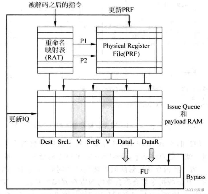
Read the register before the pipeline launch stage , The number of required memory heap read ports is small , The transmit queue requires more area to store operands , And the source operand needs to go through two reads and one write , That is, read it from the register , Write to the transmission queue , Then read it from the transmission queue and send it to FU In the implementation of , Consume more energy , It is not conducive to low-power processors .
Reading registers after the transmit phase is just the opposite .
The choice between these two methods directly determines the implementation of register renaming , When using reorder cache ROB When renaming registers , Generally, the launch form of data capture will be used . Because when the instruction leaves the assembly line smoothly , You need to move its results from the reorder cache to ARF in , Using data capture method can not care about the position change of this instruction .
8.1.3 Compress VS Uncompressed
It determines the difficulty of designing other components in the launch stage , It also affects the power consumption of the processor .
(1) Compress
When the command is selected and left , Idle positions will appear in the transmission queue , After compression , This free position will be crowded out , In this way, all the instructions are close together again . Ensure that the idle idle is at the top of the transmission queue , At this time, you only need to write the renamed instruction to the upper part of the launch queue .
The way to do it is , You need to add a multiplexer to each table entry , Used to get the table item from it ( When compressed ) Or itself ( When incompressible ) Select a .
If a transmission queue can compress two entries per cycle , Then the content of each table item has three sources , That is, the above table item 、 The above table items and themselves , Therefore, more cabling resources are needed .
It is also necessary to generate different control signals for multiplexers of different table items , Increased the complexity of the design .
The advantage of compression is that its selection circuit is relatively simple , In order to ensure that the processor can execute instructions in parallel to the greatest extent , Generally, the oldest instruction is preferred from all prepared instructions to FU In the implementation of , This is also called oldest-first, The transmission queue of this compression method has naturally followed the latest -> The oldest order arranges the instructions .
If any instruction is selected in the current cycle , Then all instructions newer than it can be selected in this cycle , This is according to oldest-first principle .
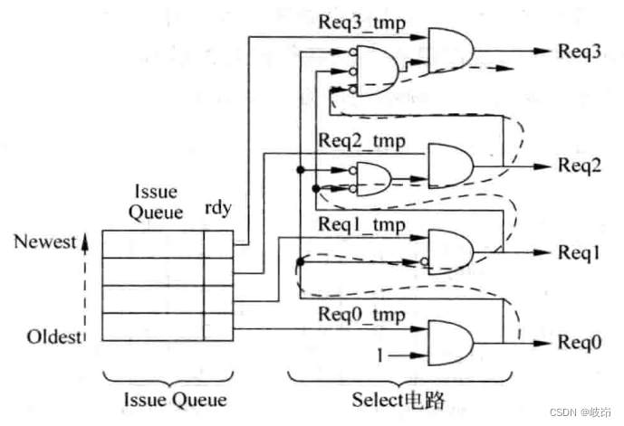
The delay of this design method is proportional to the capacity of the transmission queue , The more instructions can be held in the transmission queue , The greater the delay .
The advantages of the compressed transmission queue are as follows :
(a) The distribution circuit is simple , The free space in the launch queue is always at the top , Just use the write pointer of the transmit queue , Point to the first free space at present .
(b) The selection circuit is simple , Because this method makes the instructions in the transmission queue follow from bottom to top “ newest ” To “ Oldest ” The order is arranged . The oldest instruction in the transmit queue , And it exists RAW Correlation instructions are also the most .
shortcoming :
(a) It's a waste of silicon chip area , For example, one transmission queue corresponds to two FU when , Two instructions should be selected and sent to FU In the implementation of , Then the transmission queue needs to support at most two table entries , Complex multiplexers and a large amount of cabling resources are required , Increased the complexity of hardware .
(b) High power consumption , Many instructions in the launch queue need to be moved every week .
(2) Uncompressed transmit queue
Whenever an instruction leaves the transmission queue , Other instructions in the transmission queue will not be moved , But stay where you are . The advantage is that the power consumption is greatly reduced , Reduce the area of multiplexer and wiring . The disadvantage is to achieve oldest-first Function selection circuit , You need to use more complex logic circuits , There will be a greater delay . The distribution circuit also becomes more complex , It is impossible to write instructions directly to the upper part of the transmission queue as in the compression method , Instead, you need to scan all the space in the transmission queue .
8.2 The pipeline of the launch process
8.2.1 Pipeline of non data capture structure
An instruction entering the transmission queue is FU perform , We must wait until the following conditions are true :
(a) All the source operands of this instruction are ready ;
(b) This instruction can be selected from the transmit queue , That is, it can be launched only with the permission of the arbitration circuit ;
(c) Need to be able to read from registers 、payload Or bypass the network to get the value of the source operand .
The above three conditions occur in sequence , For a source register , If it is written to the transmission queue , Still in a state of unprepared , Wait until some time later , It becomes ready , This process is called wakeup state , This requires a bypass network to notify each source register in the transmit queue . The process of awakening can be very simple , It can also be complicated , The simplest way is when an instruction is in FU When you get results in , Set all source registers in the transmit queue that use the calculation result of this instruction to the ready state .
The launch process is divided into two pipeline stages: wake-up and blanking . In the wake-up phase , All relevant registers in the transmission queue will be set to the ready state ; And in the arbitration stage , The arbitration circuit will be used to select the most appropriate instruction from the transmission queue to FU in .
Through the bypass network in the processor , It can advance the wake-up process .
The arbitration and wake-up operations performed in the same cycle are serial . Only when the arbitration circuit selects the command that can be transmitted , Only then can the source register related to the transmission queue be awakened , And only when these two difficulties are completed in one cycle , Can be carried out back to back RAW Relevance directive .
If you want to exist RAW Dependent adjacent instructions can be executed back-to-back , The arbitration and wake-up operations of the pipeline must be completed in one cycle , Form an atomic operation .
Because the arbitration and wake-up circuits are relatively complex , Put them in one cycle , It will definitely make the clock cycle longer , The processor frequency becomes low . And separate them , Reduce the negative impact on the clock cycle , Increased processor frequency , But it will affect the number of instructions that a superscalar processor can execute in parallel per cycle . First stage assembly line is added , There will also be the following negative effects :
(a) When branch prediction fails , Punishment increases ;
(b)Cache The number of cycles visited increases
(c) The processor needs more gates , Make the capacitance larger , Resulting in increased power consumption .
8.2.2 Data capture pipeline
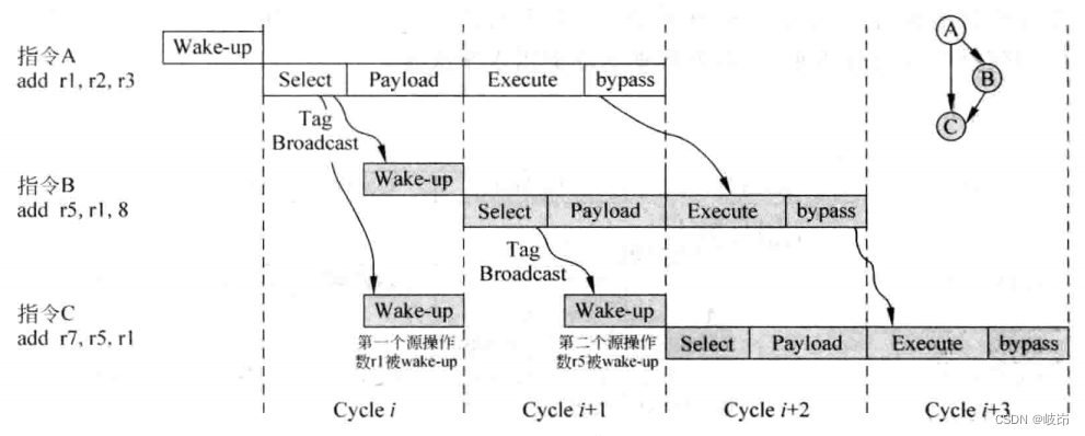
After the instruction is selected by the arbitration circuit , Other instructions in the transmission queue will also be awakened in the same cycle , At the same time, return to read payload RAM, These two operations are performed in parallel , All source operands of the instruction can be obtained at the end of this cycle , In this way, it can be delivered in the next cycle FU In the implementation of .
Selection and reading of instructions payload RAM Put it in an assembly line , Also complex will FU The calculation results of capture payload RAM in , Obviously, a lot of things have been done in this cycle , In particular, the cycle time of this processor becomes too large . meanwhile , When FU When the number of is relatively large ,FU As a result, the bypass network will also occupy expensive hardware resources and too much time , Therefore, the pipeline can be subdivided in the next step .
In order to keep the relevant instructions executed back-to-back , Still put the arbitration and wake-up operations in one cycle , Because of multi port payload RAM Take up too much time , So put it in a separate flow section , After the instruction is selected by the arbitration circuit , Wake up all relevant registers in the transmission queue , Then in the next cycle payload RAM Read . Because it is placed in a separate flow section , So it has a much smaller impact on the cycle time of the processor . The source operand is from payload RAM After reading it out , It can be delivered in the next cycle FU To perform the , The result of the instruction is FU After being calculated in , It will not bypass immediately in the current cycle , Instead, the bypass process is put into the next flow section , In the bypass stage of the flow section ,FU The result will be sent to payload RAM and FU The input end of the .
8.3 Distribute
When the transmission queue is designed in an uncompressed way , The distribution circuit needs to be able to scan the entire transmission queue , Find four free entries and put 4 Instructions are written .
The distribution circuit of the transmission queue will scan the... Of each table item in the transmission queue , Find four free entries and write four instructions to .
The allocation circuit of the transmission queue will scan the idle flag of each table item in the transmission queue , Find 4 Free entries , Write the renamed instruction into it , Although the process of finding four free table entries is carried out in parallel , But it still takes some time to complete . Actually , The time required for the whole allocation process is the capacity of the transmission queue , And the number of instructions written per cycle .
A simple method is to divide the transmission queue into 4 part , Find a free table entry in each section . The disadvantages are obvious , If there is no free space in a segment , At this time, even if other segments are idle , This section cannot accept new instructions , Therefore, a transmit queue cannot be written in one cycle 4 There are instructions . And the register renaming stage is carried out in the order specified by the program , Instructions A Unable to write to the transmit queue , Will lead to subsequent instructions B、C and D Cannot be written to the transmission queue . Reduce the performance of the processor , You can use cache to cache the instructions of the transmit queue that cannot be written , So that they do not hinder the process of writing the transmission queue by subsequent instructions , Of course, this approach will increase the complexity of the design .
Attention is also needed , Distribution circuit in the strict sense of circuit , It is in the distribution stage of the pipeline , It is not part of the launch phase .
8.4 arbitration
8.4.1 1-of-M Arbitration circuit
Why to achieve lodest-first Functional arbitration ? Considering the older the instructions , There are more instructions related to it , Therefore, priority is given to the oldest instructions , You can wake up more instructions , It can effectively improve the parallelism of instructions executed by the processor , And the oldest instructions occupy other resources , such as ROB and store buffer, The sooner these old instructions are executed , The sooner these hardware resources can be released .
Identify which instructions in the transmit queue are the oldest , You need to know the age information of these instructions , Age information indicates the sequence of instructions entering the pipeline . You can use instructions in ROB The position in is used as the age information of this instruction , But there is a problem ROB The essence is a FIFO, Therefore, using its address directly cannot express the real information of age .

Every time the write pointer flips , The new write pointer and the old write pointer are out of size . You can follow the instructions in ROB To determine the age of the instruction , And when they no longer have one “ Noodles ” Upper time , Age information cannot be determined directly from the address value , To solve this problem , Can be in ROB Add a digit in front of the address of , It is called position value . This is equivalent to adding one bit to both the write pointer and the read pointer , Every time when they “ Flip ” when , The highest position value will also be flipped .
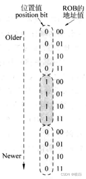
When the position value is the same ,ROB The smaller the address value of , The older the corresponding instruction ;
Different position values ,ROB The larger the address value of , The older the corresponding instruction ;
Instructions are distributed in the pipeline , The renamed instruction will be written to ROB And in the launch queue , To record age information , You need to put each instruction in ROB The address value in is also written to the transmission queue , In this way, each instruction in the transmission queue will have age information , The arbitration circuit is based on this information , Find the oldest instruction from all the prepared instructions . If the transmission queue has M Table items , This arbitration circuit is called 1-of-M Arbitration circuit , It follows oldest-first Principle realization .
The number of stages of the comparison circuit required N And the number of table entries in the transmission queue M There is a relationship between N=log2M, Therefore, when the capacity of the transmission queue is large , You need more comparator stages , That is, the delay will be greater .
In practice, the following two problems :
(a) How to shield those instructions that are not ready in the transmission queue , So that the age information of those instructions will not affect the results of the arbitration circuit ? Set the age information corresponding to those instructions that have not been prepared to infinity .
(b) How to choose the age value according to the arbitration circuit , Find the corresponding instruction in the transmission queue ?
The most direct way is to compare the age value obtained by the arbitration circuit with the age value of all instructions in the transmission queue . At that time, additional CAM circuit , Increased processor area and latency , Not a very wise approach .
8.4.2 N-of-M Arbitration circuit
How many FU Share a transmission queue , This transmission queue needs to be in a cycle for each FU Choose an instruction , This requires it to have a N-of-M Arbitration circuit .
If more than one FU There is a launch team , The capacity of the transmission queue is M, Every FU All have a special 1-of-M Arbitration circuit . When an instruction is written to an entry in the transmit queue , According to the type of this instruction , Assign this instruction to a corresponding FU, If there are FU, Will be allocated in turn or in random order , The essence of this allocation process can be realized through a multiplexer , It will show each ready Signals are assigned to different arbitration circuits according to the type of instruction , Because each table item in the transmission queue may store different types of instructions , So each FU All arbitration circuits have M Inputs , Perform a complete 1-of-M The arbitration process of , Whole N-of-M The delay of the blanking circuit is only 1-of-M.
Introduce a new problem , One ALU Type of instruction is assigned to that ALU Well ? Rotation allocation can be adopted , Although there is no guarantee of strictness oldest-first.
For many modern processors , Generally, it is executed at most every cycle 4~6 Orders , Typical examples include :
Addition and subtraction 、 Logic 、 displacement 、 Multiplication 、 division 、 Access memory 、 Access coprocessor 、 Single instruction multiple data operation , Floating point addition and subtraction 、 Floating point multiplication 、 Floating point division .
Generally speaking , Will add and subtract 、 Logical operation and shift operation are combined in one FU in ; Combine integer multiplication and division ; Combine access memory and access coprocessor ; Combine all floating-point operations ;
When more FU When there is a transmission queue , The capacity of this transmission queue also needs to be increased , This increases the delay of the arbitration circuit ; If you make less FU Share a transmission queue , You need a larger number of launch queues , At this time, the wake-up operation requires more wiring resources and comparator circuits , The delay and power consumption of the wake-up circuit are increased .
8.5 Wake up the
8.5.1 Wake up of single cycle instruction
Wake up means that the instruction selected by the arbitration circuit compares the number of its destination register with the number of all source registers in the transmission queue , And mark those source registers with equal comparison results .
In general , The number of arbitration circuits is equal to issue width.
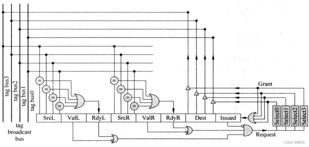
The table items are as follows :
(a)ValL: Whether the first source register exists in the instruction , If there is no first source register in the instruction , Then there is no need to wake up the source register .
(b)SrcL: The number of the first source register in the instruction ;
(c)RdyL: Whether the first source register in the instruction has been awakened and is in the ready state ;
(d)ValR、SrcR and RdyR: The state of the second source register in the instruction ;
(e)Dest: Number of destination register ;
(f)Issued: After an instruction is selected by the arbitration circuit , May not leave the launch queue immediately , So it needs to be marked , Such an instruction will not send a request signal to the arbitration circuit .
In a RISC Command set , Most of ALU All types of instructions are single cycle , Such an instruction can wake up other instructions in the transmission queue in the current cycle selected by the arbitration circuit , The awakened instruction can obtain the source operand through the bypass network , So as to realize back-to-back execution , Now let's sort out the wake-up process of single cycle instructions :
First step : The instruction selected by the arbitration circuit will send the number of its destination register to the corresponding bus .
The second step : The value on each bus is compared with the number of the source register of all instructions in the transmit queue , If we find equality , Then mark this source register as ready .
The third step : When all the operands of an instruction in the transmit queue are ready , And it has not been selected by the arbitration circuit , It can send a request signal to the corresponding arbitration circuit .
Step four : If the arbitration circuit finds a higher priority instruction, it also sends a request signal , Then the current instruction will not get an effective response , This instruction will send a request signal to the arbitration circuit in the next cycle , If one of the arbitration circuits fails to give a response signal several times , The request of this instruction can be sent to another arbitration circuit , Because another arbitration circuit is likely to be idle at this time . If an effective response signal is obtained from the arbitration circuit , Then the response signal will mark the instruction as selected , This instruction will not continue to send a request signal to the arbitration circuit in the next cycle . Why not directly let the selected instruction leave the launch queue immediately ? Because if an instruction is used load The result of the instruction , Even if it is selected by the arbitration circuit , You can't leave the launch queue immediately .
Step five : This instruction in the transmission queue is based on the received response signal , Send the number of its destination register to the corresponding bus , Used to wake up all relevant source registers in the transmission queue , At the same time, this instruction can be sent to FU To perform the .
8.5.2 Wake up of multi cycle instructions
When an instruction cannot be executed in one cycle , The current cycle selected by the arbitration circuit can no longer wake up other instructions in the transmission queue , And it needs to be based on FU Number of cycles executed in , Delay the wake-up process .
The wake-up process is divided into two main stages , The first stage is to send the number value of the selected instruction destination register to the bus , The second stage is to compare the values on the bus with the numbers of all source registers in the transmit queue , Therefore, delay the wake-up process , That is to delay these two stages , This leads to two methods , One is called delayed broadcasting delayed tag broadcast, The other is called delayed wakeup delayed waken.
The method of delaying broadcasting refers to if it is found that the execution cycle of the instruction selected by the arbitration circuit is greater than 1, Then in the selected current cycle , The number of the destination register of this instruction is not sent to the bus , It is based on the number of cycles that the selected instruction needs to execute N, Delay N-1 After a period , Just send it to the bus .
However, when instructions operate on a dedicated bus , There is no problem doing this , But when instructions and other operations share the same bus , It may compete with other instructions to use the bus . To solve this problem , You can add this FU Number of corresponding buses , however , When there are many such situations in processing , It will lead to a large number of buses , This will greatly increase the complexity of the wake-up circuit , It is unacceptable in the actual design . If the number of buses is not increased , Then you need to record the number of execution cycles of each instruction in the processor . The advantage of this method is that it does not increase the delay of the arbitration circuit , But it caused the loss of performance .
How to solve this problem ? It is possible to let the instruction send a request to the arbitration circuit , First, query the table , If the form rejects it , Then this instruction will not send a valid request signal to the arbitration circuit , In this way, the opportunity can be left to other instructions . But this approach requires serial access to tables and arbitration circuits , So it will increase the cycle time of the processor ,
The method of delaying broadcasting is to delay the first stage of the wake-up process , by comparison , Delayed wakeup is to delay the second stage . Delayed wakeup is in the transmission queue , Each instruction corresponds to ready The status is register with delay function . Shift register is used to realize the effect of delayed wake-up , Because in the pipeline decoding stage , The number of execution cycles required for each instruction can be known , Encode the execution cycle of each instruction , The value after encoding is abbreviated as DELAY.
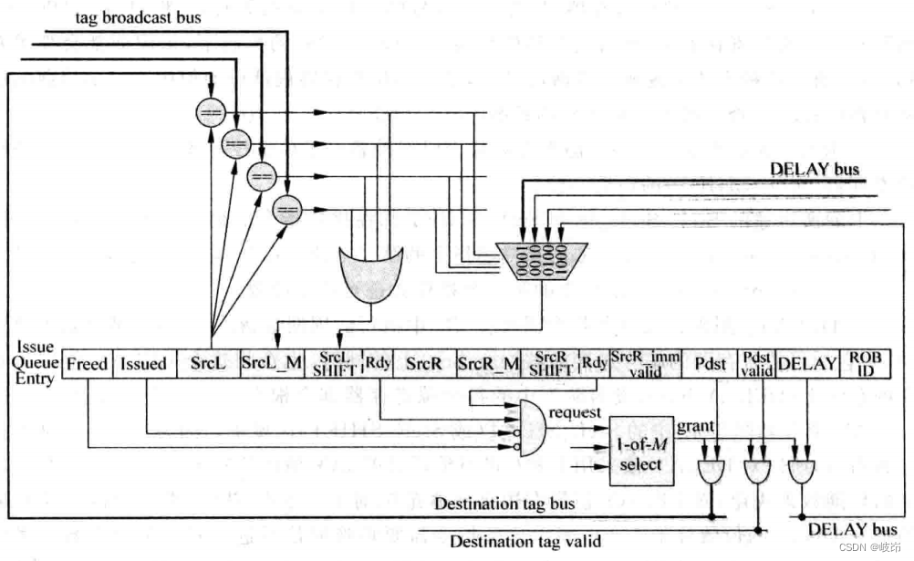
The table items are as follows :
(a)Freed: Indicates whether this table item is idle , When an instruction is written into it , This entry is no longer idle ; This instruction is selected by the arbitration circuit , And there will be no problem with the shortcomings , This instruction can leave the launch queue , This table item can become idle . It should be noted that , After an instruction is selected by the arbitration circuit , There is no guarantee that this instruction will get the desired operand , When the operand of this instruction comes from load When the command , The processor may use speculative wakeup . It is not a very direct thing to manage whether a table item in the transmission queue is idle , The easiest way is when an instruction leaves the pipeline smoothly , To make the table items it occupies in the transmission queue become idle . But this will cause many invalid instructions to occupy the launch queue , Reduce the available capacity , It reduces the possible parallelism of the processor .
(b)SrcL_M: When the comparison results of register numbers are equal , The first place will be set 1(M Express match); When this instruction receives the response signal given by the arbitration circuit , This one will be cleared 0, It uses the shift register for arithmetic right shift enable signal , When it's for 1 when , The shift register will be arithmetically shifted one bit to the right every cycle .
(c)SrcL_SHIFT: shift register , When the comparison results of register numbers are equal , The corresponding DELAY The value is written to this shift register , Then it is controlled by the shift enable signal , Every week, the arithmetic will be shifted one place to the right , In this way, the function of delayed wake-up is realized .
(d)SrcR_imm_valid: Indicates whether the second operand of the instruction is an immediate number ;
(e)DELAY: It is used to record each instruction in FU Number of cycles executed in , When an instruction is selected by the arbitration circuit , Send the number of its destination register to the bus at the same time , Will also put this DELAY The value is sent to the corresponding bus , Each source register in the transmit queue will be based on the comparison result , Choose the right one DELAY value . For one in FU It needs to be implemented in L For a cycle of instructions ,0 The number of digits is equal to L-1, Indicates the number of cycles that this instruction needs to delay the wake-up signal .
(f)ROB ID: This instruction is in ROB Position in , This value is used as the age information of the instruction , The arbitration circuit can realize oldest-first Command selection .
8.5.3 Speculation awakens
The wake-up methods mentioned above are all based on one premise , That is, the instruction is FU The number of execution cycles in is predictable , For unpredictable instructions such as :
(a)Load Instructions , It's in FU The number of cycles executed in depends on D-Cache Whether to hit , In a city with L1,L2,L3 Cache and DRAM Typical processor ,load The delay is uncertain .
(b) In some processors , Some special cases are defined .
For these instructions, the number of cycles executed is uncertain , It can be handled in the simplest way , When this instruction is executed , Wake up other relevant instructions .
for example laod Instructions , If L1 D-Cache hit , Then when laod Instruction execution completed , When you get the data you need , The number of the destination register of this instruction is sent to the corresponding bus , Wake up the relevant registers in the transmission queue .
In the design D-Cache when ,Cache Whether the hit information can be obtained before the data , for example laod The address is calculated in the first cycle of instruction execution , Second cycle access Tag SRAM Judge whether it hits , The third cycle writes the read data to load In the destination register of the instruction , In this design D-Cache in , Execute the second cycle to know Cache Hit or not .
For delayed wakeup , Just for load The order says , You still need to get D-Cache Missing condition , The instruction cannot obtain operands through the bypass network , It can't be in FU In the implementation of , And you can't stop waiting for operands , This will make FU Unable to accept other new instructions , Seriously affect the performance of the processor . The best way is to order B Return to the transmission queue .
Because of reading L1,L2 even to the extent that L3 Cache The number of cycles required is certain , So we can use the method of delaying wakeup , But the reading time is uncertain , for example DRAM The interview of , Can only wait for DRAM When you really get the data in , Wake up the register related to the transmission queue .
In modern processors, instructions are selected by the arbitration circuit at the same time , According to the number of execution cycles required by this instruction , To wake up other related instructions , So when the selected instruction calculates the result , The command awakened by it is about to enter the execution phase , Operands can be obtained through the bypass network , So as to realize back-to-back execution .
load Instructions are mostly at the top of the Correlation , If you wait until its result is calculated before you wake up , Some potential opportunities for parallel execution will be lost , Thus reducing the performance of the processor , Therefore, it is necessary to use the prediction method to predict the number of cycles of instruction execution , Before the instruction gets the result , Wake up the relevant instructions , This method is called speculative arousal .speculative wake up.

load Instructions are divided into three pipeline segments in the execution phase ,Cal Addr Stage is used to calculate the address carried by the instruction ,TLB/Tag The stage will be visited at the same time TLB and D-Cache, In this cycle, you will get the physical address corresponding to the virtual address , At the same time, you will get D-Cache Whether to hit the message , stay Data The stage can start from D-Cache Get the required data , And write it to the destination register . Attention should be paid to the state recovery after prediction failure .
If software processing is used TLB defect , You need to deal with exceptions , wait until load When an instruction becomes the oldest instruction in the pipeline , Put all the instructions in the pipeline ( Include load Instructions ), In the corresponding exception handler TLB Missing situation handling , And then put it back on the table load Instructions and subsequent instructions are taken into the pipeline .
If hardware processing is adopted TLB defect , Then there is no need to laod Instructions are fetched back to the pipeline for execution ,load The related instructions behind the instructions only need to return to the transmission queue , So if the hardware handles TLB Missing way , You can restore the process and D-Cache miss Put the recovery process together , This saves hardware resources .
With different structures D-Cache, For speculation, the process of arousal is influenced by . Adopt virtual addressing , Physical labels , Then visit TLB At the same time , You can also use virtual addresses to access D-Cache, This parallel locality will increase the efficiency of execution . Such as using physics index, Physics tag When , You must visit TLB And get the physical address , Then we can visit D-Cache, This will D-Cache The access process of is completely serialized , Therefore, a longer execution time is required . If using virtual index, Physics tag, There is no need to visit TLB, Directly use virtual address to access D-Cache That's all right. , Only when D-Cache Access is only needed when it is missing TLB( because L2 Cache Are accessed by physical addresses ), No access required TLB This means that this aspect will be shortened D-Cache Time of visit .
load After the instruction is selected by the arbitration circuit , It takes two cycles to wake up the relevant instructions , In these two cycles , The arbitration circuit can select those and load Irrelevant instructions , Call these two cycles Independent window. And from load The instruction starts to wake up the relevant instruction , Know whether it will find itself D-Cache hit / defect , There is also a gap between two and walk , Call these two cycles Speculative Window.

It should be noted that ,SW The instructions in the window are not necessarily the same as load Instructions are relevant , For example, those who are load The instruction waked up by the instruction is not immediately selected by the arbitration circuit , Will make SW The instructions in the window are not actually used load The result of the instruction ; and IW The instructions in the window are not necessarily the same as load Instruction related , Because it can be compared with others load The directive SW Windows are coincident .
边栏推荐
- 【愚公系列】2022年7月 Go教学课程 005-变量
- 【数据聚类】基于多元宇宙优化DBSCAN实现数据聚类分析附matlab代码
- MATLAB實現Huffman編碼譯碼含GUI界面
- Complete collection of common error handling in MySQL installation
- 【滤波跟踪】基于matlab扩展卡尔曼滤波EKF和无迹卡尔曼滤波UKF比较【含Matlab源码 1933期】
- SwiftUI Swift 内功之 Swift 中使用不透明类型的 5 个技巧
- 聊聊SOC启动(十一) 内核初始化
- EasyUI learn to organize notes
- 千人规模互联网公司研发效能成功之路
- In SQL, I want to set foreign keys. Why is this problem
猜你喜欢

Some opinions and code implementation of Siou loss: more powerful learning for bounding box regression zhora gevorgyan

18 basic introduction to divider separator component of fleet tutorial (tutorial includes source code)
【最短路】ACwing 1127. 香甜的黄油(堆优化的dijsktra或spfa)
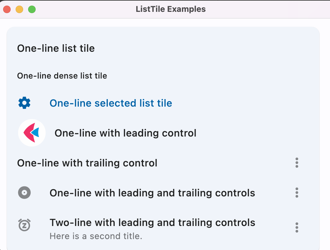
Flet教程之 14 ListTile 基础入门(教程含源码)
![[extraction des caractéristiques de texture] extraction des caractéristiques de texture de l'image LBP basée sur le mode binaire local de Matlab [y compris le code source de Matlab 1931]](/img/65/bf1d0f82878a49041e8c2b3a84bc15.png)
[extraction des caractéristiques de texture] extraction des caractéristiques de texture de l'image LBP basée sur le mode binaire local de Matlab [y compris le code source de Matlab 1931]
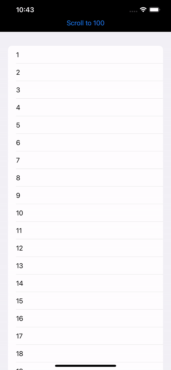
Swiftui tutorial how to realize automatic scrolling function in 2 seconds
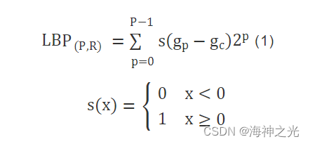
【紋理特征提取】基於matlab局部二值模式LBP圖像紋理特征提取【含Matlab源碼 1931期】
Test the foundation of development, and teach you to prepare for a fully functional web platform environment
![[filter tracking] comparison between EKF and UKF based on MATLAB extended Kalman filter [including Matlab source code 1933]](/img/90/ef2400754cbf3771535196f6822992.jpg)
[filter tracking] comparison between EKF and UKF based on MATLAB extended Kalman filter [including Matlab source code 1933]
![[shortest circuit] acwing1128 Messenger: Floyd shortest circuit](/img/a4/783bdcc2b97938efc77b7da6442866.png)
[shortest circuit] acwing1128 Messenger: Floyd shortest circuit
随机推荐
Matlab implementation of Huffman coding and decoding with GUI interface
【问道】编译原理
清华姚班程序员,网上征婚被骂?
Rationaldmis2022 advanced programming macro program
Various uses of vim are very practical. I learned and summarized them in my work
About how to install mysql8.0 on the cloud server (Tencent cloud here) and enable local remote connection
Explore cloud database of cloud services together
SwiftUI Swift 内功之 Swift 中使用不透明类型的 5 个技巧
Ask about the version of flinkcdc2.2.0, which supports concurrency. Does this concurrency mean Multiple Parallelism? Now I find that mysqlcdc is full
STM32 entry development write DS18B20 temperature sensor driver (read ambient temperature, support cascade)
STM32入门开发 采用IIC硬件时序读写AT24C08(EEPROM)
There are so many factors that imprison you
【紋理特征提取】基於matlab局部二值模式LBP圖像紋理特征提取【含Matlab源碼 1931期】
Talk about SOC startup (x) kernel startup pilot knowledge
Complete collection of common error handling in MySQL installation
正在运行的Kubernetes集群想要调整Pod的网段地址
R language uses the quantile function to calculate the quantile of the score value (20%, 40%, 60%, 80%), uses the logical operator to encode the corresponding quantile interval (quantile) into the cla
【纹理特征提取】基于matlab局部二值模式LBP图像纹理特征提取【含Matlab源码 1931期】
Talk about SOC startup (VI) uboot startup process II
Programming examples of stm32f1 and stm32subeide -315m super regenerative wireless remote control module drive