当前位置:网站首页>Advance Computer Network Review(1)——FatTree
Advance Computer Network Review(1)——FatTree
2022-07-06 09:02:00 【Zheyuan Zou】
This series is right 21~22 Review outline of advanced computer network course in summer semester of the academic year , This is the first article in this series :FatTree Use in the data center , The main coverage is as follows :
1. Topology and addressing scheme
2. Routing algorithm , Find the routing path between any two hosts
Original paper :《A Scalable, Commodity Data Center Network Architecture》SIGCOMM’08
One 、 Topology and addressing scheme
First of all, this article reviews some problems in data center communication , Then, aiming at these problems, a method based on fat tree (Fat Tree) Of Clos Topology to connect commodity Ethernet switches . The proposed architecture is as follows , It shows a k Yuanpang tree (k=4) The architecture of the figure :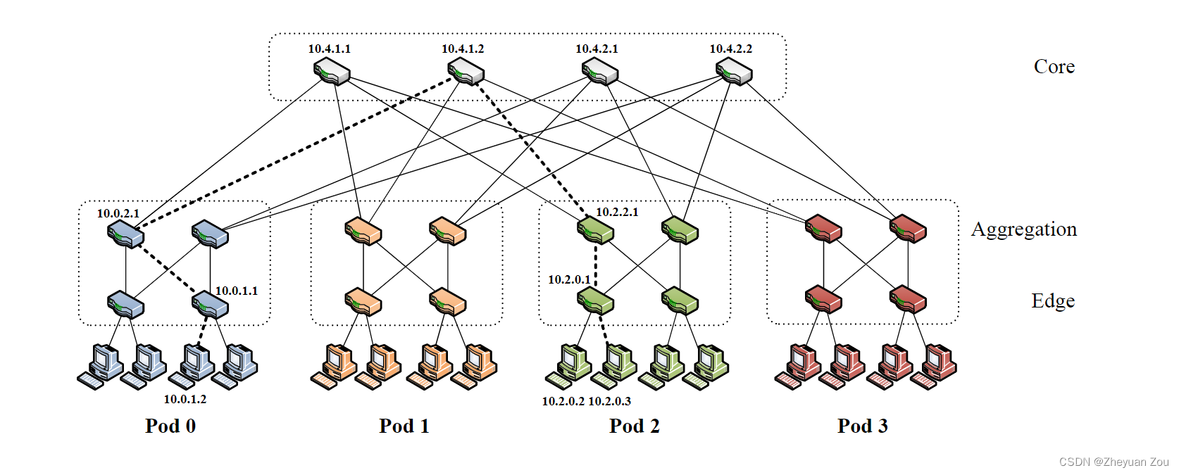
k Yuanpang tree The architecture has the following characteristics :
1. Yes k individual pods, Every pods contain 2 layer , Each layer contains k 2 \frac{k}{2} 2k A switch .
2. every last k Oral exchange , k 2 \frac{k}{2} 2k Ports are directly connected to the host at the bottom (hosts), The rest k 2 \frac{k}{2} 2k Ports are connected up to the high-level switch .
3. Topmost ( k 2 ) 2 {(\frac{k}{2})}^2 (2k)2 Core switches also have k Ports , And The first i Port is just connected to i individual pod, therefore pod Continuous ports in the aggregation layer are represented by k 2 \frac{k}{2} 2k Step by step connection to the core switch (?, This needs to be understood ).
4.k In the yuanpang tree, for different positions pod Host in , Yes ( k 2 ) 2 {(\frac{k}{2})}^2 (2k)2 The shortest path is optional , But only one of them will be chosen .
Now let's take a look at the addressing scheme in this architecture , First of all, the original text clearly states , All in the block IP The addresses are taken from Private address space 10.0.0.0/8 in . The addressing method is located at different levels according to the equipment , It can be divided into the following three situations :
1.pod Switches in , For this kind of switch , The addressing scheme is 10.pod.switch.1,pod That's where it is pod Number ,switch It is in its own pod Number in , This number follows From left to right , Bottom up ( Be careful The priority of left and right is higher than that of up and down ) The addressing order of , The value range is [0,k-1]. For example, in the diagram above pod2, from 4 In a grid of switches , The compilation space is [0,3], On the lower left is 0, On the lower right is 1, On the left is 2, On the right is 3.
2. Core switch , For this kind of switch , The preparation scheme is 10.k.j.i,k Is the element , In the diagram k Namely 4. The original says (j, i) Refers to the switch in ( k 2 ) 2 {(\frac{k}{2})}^2 (2k)2 In the core switch grid coordinate , The scope is [1, k 2 \frac{k}{2} 2k], from Start addressing in the upper left corner . In fact, in the diagram above , We can regard the core switch layer as a 2x2 Square grid to address .
3. host (host), The address scheme of the host is 10.pod.switch.ID,pod,switch Meaning and 1 In the same way , I won't repeat .ID Indicates the location of the host in its subnet , The value range is [2, k 2 + 1 \frac{k}{2} + 1 2k+1], Address from left to right , because 1 Occupied by the switch ,255 Out-of-service . There is also a sentence mentioned in the original text , Each low-level switch is responsible for one containing k 2 \frac{k}{2} 2k A host of /24 subnet (k < 256).
Two 、 Routing algorithm
This part discusses how to complete routing in the above architecture .
1.pod Internal information exchange
First , In a pod Switches in ( Whether low or high ) All keep this pod Prefixes of all subnets under its jurisdiction , This also means that if it is a pod Internal information forwarding . Then this message is being forwarded to pod Of High level switch Will be forwarded to the corresponding subnet .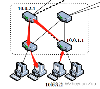
2.pod The exchange of information between
The routing table used in this article is two-level , The first level uses prefix matching , The second level uses suffix matching . Prefix matches are used for pod Internal routing , Suffix matches for pod The route between , The record of the secondary table in the primary table is 0.0.0.0/0.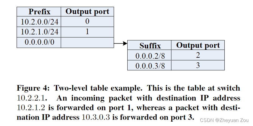
This involves the generation of routing tables for two devices , One is pod The switch inside , Another is the core switch , Their algorithms for generating routing tables are different .
First of all to see pod The switch in , There are also two situations , One is Switch on top , The other is Switch at the bottom .
For being in Top level switch , The routing table generation algorithm is as follows :
among 3-5 Line this code is for pod Internal switching provides routing items , and 6-9 Yes, it is pod The exchange between provides routing items , According to the formula (i-2+z)mod(k/2)+(k/2) The calculated port can span pod The information of accessing the specified host is forwarded from the correct port , The purpose of modular operation is Ensure load balancing .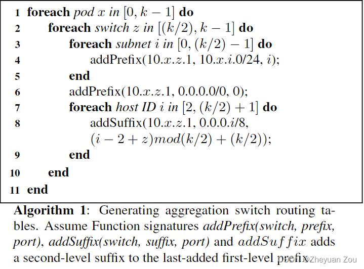
For switches located at the bottom , It does not need to be responsible for forwarding to the subnet , Only responsible for forwarding to the specified host , therefore 3-5 The logic of the line can be erased , Of course The switch number in the second line should also be moved :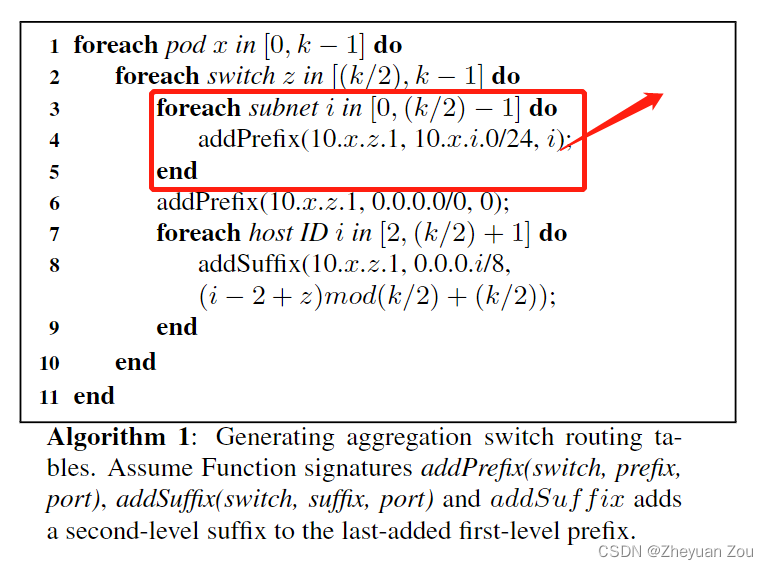
For core layer routing , The routing table generation algorithm is as follows , In fact, it is the designated pod, Forward from the specified port ( As I said before, the core switch is i Port is just connected to i individual pod):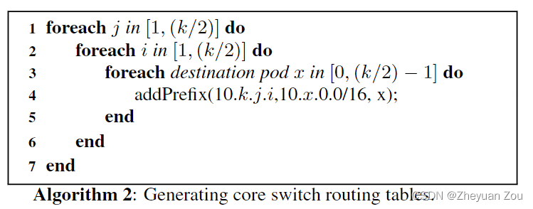
At last, the article gives a cross pod Routing examples :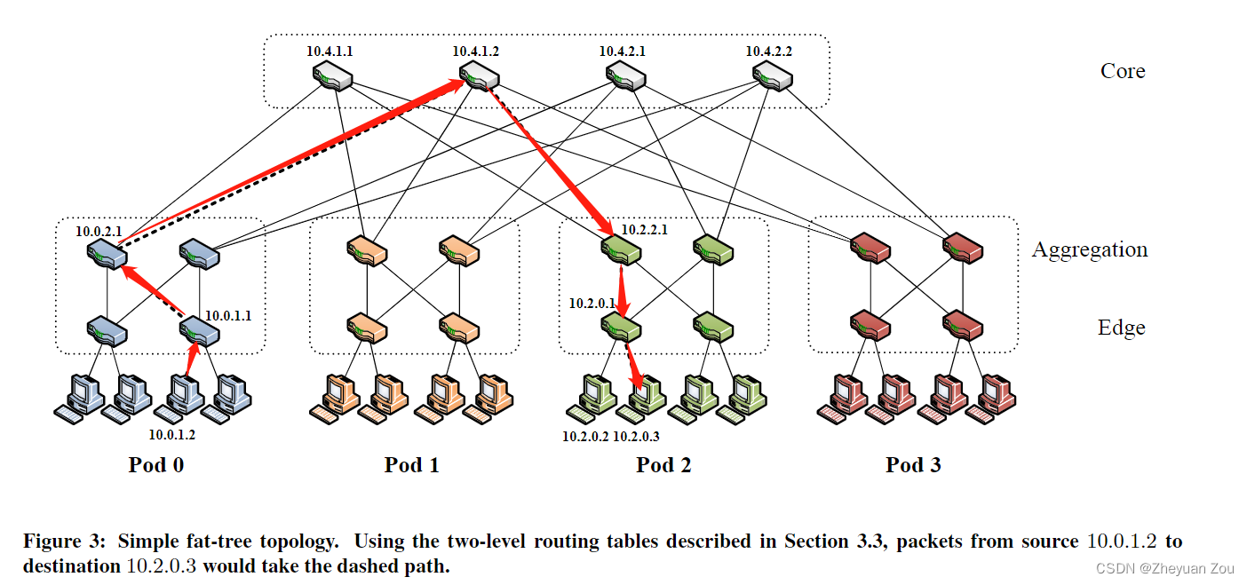
1. from 10.0.1.2 To 10.0.1.1, from Standard switching technology complete , because 10.0.0.1 Is the gateway of the source host .
2.10.0.0.1 To 10.0.2.1, Check the secondary routing table ( The suffix match , Be careful i=3), Send it from the corresponding port .
3.10.0.2.1 To 10.4.1.2, Check the secondary routing table , Forward from the corresponding port .
4. from 10.4.1.2 To 10.2.2.1, You can get the first level routing table 10.2.0.0/16 The matching of , To forward to pod2.
5. from 10.2.2.1 To 10.2.0.1, Because at this time, it is in the same place with the destination network pod in , So at this time, you can get a match from the first level routing table 10.2.0.0/24.
6. from 10.2.0.1 To 10.2.0.3, from Standard switching technology complete .
This is the end of combing and learning this article .
边栏推荐
- KDD 2022论文合集(持续更新中)
- [OC foundation framework] - [set array]
- UML diagram memory skills
- R language ggplot2 visualization, custom ggplot2 visualization image legend background color of legend
- CUDA实现focal_loss
- [oc]- < getting started with UI> -- common controls - prompt dialog box and wait for the prompt (circle)
- Implement window blocking on QWidget
- KDD 2022 paper collection (under continuous update)
- LeetCode:394. String decoding
- Selenium+Pytest自动化测试框架实战(下)
猜你喜欢
Selenium+pytest automated test framework practice
Esp8266-rtos IOT development
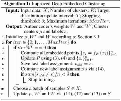
Improved deep embedded clustering with local structure preservation (Idec)
![[sword finger offer] serialized binary tree](/img/e2/25c9322da3acda06c4517b0c50f81e.png)
[sword finger offer] serialized binary tree
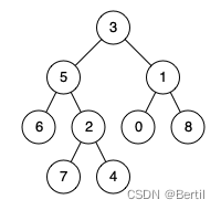
LeetCode:236. The nearest common ancestor of binary tree

I-BERT
![[MySQL] limit implements paging](/img/94/2e84a3878e10636460aa0fe0adef67.jpg)
[MySQL] limit implements paging

Advanced Computer Network Review(5)——COPE
![[text generation] recommended in the collection of papers - Stanford researchers introduce time control methods to make long text generation more smooth](/img/10/c0545cb34621ad4c6fdb5d26b495ee.jpg)
[text generation] recommended in the collection of papers - Stanford researchers introduce time control methods to make long text generation more smooth

什么是MySQL?MySql的学习之路是怎样的
随机推荐
【嵌入式】使用JLINK RTT打印log
Intel distiller Toolkit - Quantitative implementation 2
[oc]- < getting started with UI> -- common controls uibutton
【文本生成】论文合集推荐丨 斯坦福研究者引入时间控制方法 长文本生成更流畅
The ECU of 21 Audi q5l 45tfsi brushes is upgraded to master special adjustment, and the horsepower is safely and stably increased to 305 horsepower
I-BERT
Navicat Premium 创建MySql 创建存储过程
Problems encountered in connecting the database of the project and their solutions
LeetCode:124. 二叉树中的最大路径和
[OC]-<UI入门>--常用控件-提示对话框 And 等待提示器(圈)
UML图记忆技巧
Mise en œuvre de la quantification post - formation du bminf
LeetCode:673. Number of longest increasing subsequences
一改测试步骤代码就全写 为什么不试试用 Yaml实现数据驱动?
LeetCode:836. 矩形重叠
MYSQL卸载方法与安装方法
LeetCode:836. Rectangle overlap
The ECU of 21 Audi q5l 45tfsi brushes is upgraded to master special adjustment, and the horsepower is safely and stably increased to 305 horsepower
Pytest参数化你不知道的一些使用技巧 /你不知道的pytest
什么是MySQL?MySql的学习之路是怎样的