当前位置:网站首页>[ANSYS] learning experience of APDL finite element analysis
[ANSYS] learning experience of APDL finite element analysis
2022-07-07 07:31:00 【Xiaomu who loves reading】
List of articles
- 1、 Preface
- 2、 Online learning resources
- 3、ANSYS Relevant concepts
- 4、APDL Command specification ( part )
- 5、APDL Secondary development
- 5.1 Load the result file ( post-processing )
- 5.2 Check the overall situation of the result data ( post-processing )
- 5.3 Draw the result graph ( post-processing )
- 5.4 Output animation ( post-processing )
- 5.5 Get the data of all nodes ( post-processing )
- 5.6 Get the data of all units ( post-processing )
- 5.7 Get the data of all nodes and cells ( post-processing )
- 5.8 Obtain node and cell data at all frequency time points ( post-processing )
- Postscript
1、 Preface
Ansys On 1970 Founded in western Pennsylvania . today ,Ansys Our headquarters is still close to its origin , Located in Canonsburg, Pennsylvania ,Ansys There are more than 75 Strategic Sales Department , And has a worldwide network of partners .

Finite element method is a widely used numerical calculation method in Engineering , With its unique computing advantages, it has been widely developed and applied , As a result, a number of very mature general and professional finite element commercial software . With the rapid development of computer technology , Various engineering software has also been widely used .
When it comes to the finite element method, we must mention ANSYS Software ,ANSYS Software is America ANSYS Large general finite element analysis developed by the company (FEA) Software , It is the fastest growing in the world CAE Software , Be able to include structure 、 heat 、 The sound 、 Research on fluid and electromagnetic fields , In the nuclear industry 、 railway 、 Petroleum chemical industry 、 Aerospace 、 Mechanical manufacturing 、 energy 、 Automobile traffic 、 National defense 、 Electronics 、 Civil Engineering 、 shipbuilding 、 Biological medicine 、 light industry 、 Geology and mineral resources 、 Water conservancy 、 Household appliances and other fields have a wide range of applications .
ANSYS Is powerful , Easy to operate , Now it has become the most popular finite element analysis software in the world , Over the years FEA Ranked first in the evaluation .
Simulation is a superpower
Ansys Multi physical field simulation gives us powerful functions , It allows us to explore and predict whether the product works normally in the real world .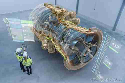
It's like being able to foresee the future , Enables you to innovate in an unprecedented way .
The ability of engineering to drive the future
Ansys Based on Modeling 、 Physics 、 Basic principles of mathematics and computer science , Simulation enables engineers to understand the behavior of their designs in millions of real-world scenes , At the same time, it can reduce 、 Even eliminate the need for expensive physical tests .Simulation helps realize :
1. 5G and 6G signal communication
2. Industrial Internet of things
3. Autopilot
4. Personalized medicine
5. Electrification
6. A new generation of energy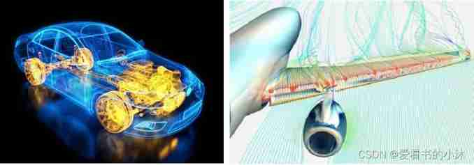
Interdisciplinary innovation
Ansys Customers accelerate innovation with simulation from components to systems :
1. Structural mechanics
2. Computational fluid dynamics
3. electromagnetism
4. photonics
5. Material properties
6. semiconductor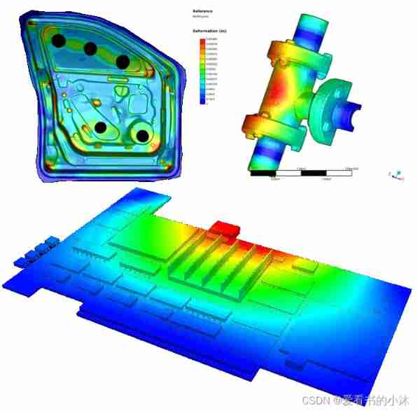
2、 Online learning resources
Ansys Official website
https://www.ansys.com/zh-cnAnsys Academic(Ansys academic )
https://www.ansys.com/zh-cn/academicAnsys Learning Forum(Ansys Learning Forum )
https://forum.ansys.com/PyAnsys Project (pip install ansys-mapdl-core)
https://docs.pyansys.com/apdl 18.2 Command online help ( Department of applied mechanics, School of mechanical engineering, Budapest University of science, technology and Economics ):
https://www.mm.bme.hu/~gyebro/files/ans_help_v182/ans_cmd/Hlp_C_CmdTOC.html
ANSYS from Release 18.1 Start online help ( The beta ), from Release 19.0 Start , Online help has become the default way to view help materials .
stay ANSYS In the local offline help of ,APDL Related commands , You can search directly through search , It can also be in Mechanical APDL—> Command Reference Now search according to the first letter of the command .
3、ANSYS Relevant concepts
3.1 Analysis function
ANSYS Analysis function of software : structural analysis 、 thermal analysis 、 Fluid analysis 、 Electromagnetic field analysis 、 Coupled field analysis .
among structural analysis There are seven types , Function as follows :
- Static analysis : It is used to solve the static behavior of the structure under static load , The linear and nonlinear characteristics of the structure can be considered . Nonlinear characteristics such as large deformation 、 Big strain 、 Stress stiffening 、 Contact 、 plasticity 、 Superbomb 、 Creep, etc .
- Characteristic buckling analysis : Used to calculate linear buckling load and buckling mode .
Nonlinear buckling analysis and cyclic symmetric buckling analysis belong to the type of static analysis , It does not belong to the type of eigenvalue buckling analysis . - modal analysis : Calculate the natural frequency and vibration mode of linear structure , A variety of modal extraction methods can be used . Computable natural modes 、 Prestress mode 、 Damped complex mode 、 Cyclic mode, etc .
- Harmonic response analysis : Determine the response of a linear structure under a load that varies sinusoidally with time .
- Transient dynamic analysis : Calculate the response of the structure under the load that changes arbitrarily with time , The same structural nonlinear characteristics as static analysis can be considered . Nonlinear full transient and linear mode superposition methods can be considered .
- Spectral analysis : Extension of modal analysis , Used to calculate the response spectrum or PSD Input ( random vibration ) Caused structural stress and strain . Single point spectrum and multi-point spectrum analysis can be considered .
- Explicit dynamic analysis :ANSYS/LS-DYNA It can be used to calculate highly nonlinear dynamics and complex contact problems .
- Special analysis : In addition to the above seven types of analysis , The following special analysis can also be carried out : crack 、 compound material 、 fatigue 、P- Such method .
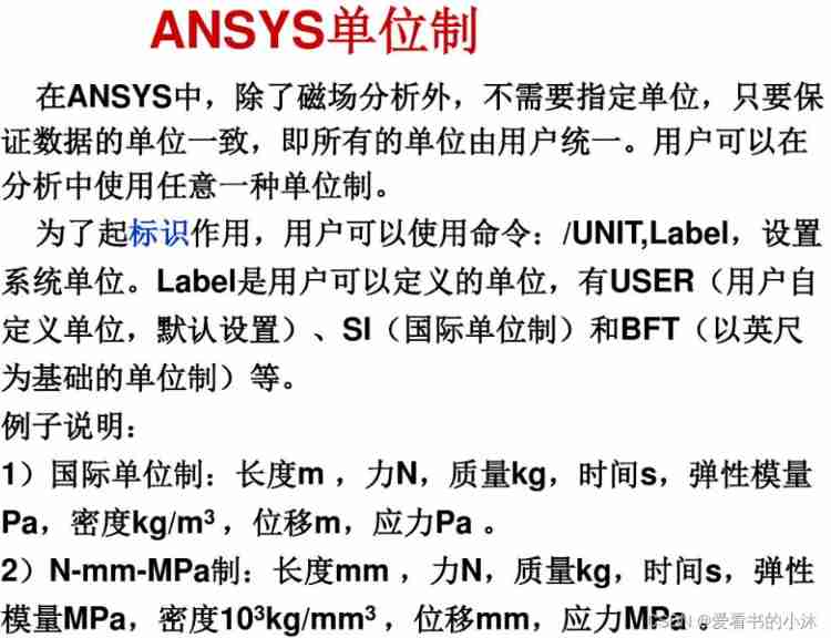
3.2 The system of units
3.3 Coordinate system
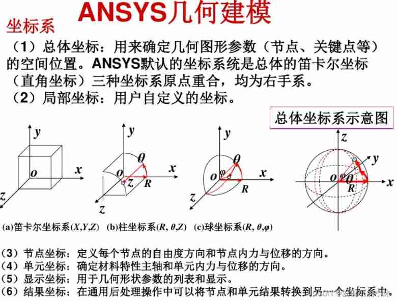
3.4 Solid model and finite element model
Nowadays, almost all finite element analysis models are modeled with solid models , Be similar to CAD.ANSYS Express the geometry of the structure mathematically , Used to fill in nodes and cells , It is also convenient to apply loads on the boundary of the geometric model . however , Geometric solid models do not participate in finite element analysis . All loads or constraints imposed on the boundary of geometric entities must be finally transferred to the finite element model ( On nodes or units ) To solve the .
Four types of elements :
- body (Volumes,3D Model ) Surrounded by faces , Represents a 3D solid .
- Noodles (Areas, The surface of the ) Surrounded by lines . Represents the solid surface 、 Flat shape or shell ( It can be a three-dimensional surface ).
- Line (Lines, It can be a space curve ) End with key , Represents the edge of the object .
- Key points (Keypoints, be located 3D Space ) Represents the corner of the object .

3.5 load
ANSYS The load in can be divided into :
- freedom DOF - Define the degree of freedom of the node (DOF) value ( structural analysis _ Displacement 、 thermal analysis _ temperature 、 Electromagnetic analysis _ Magnetic potential, etc ).
- Concentrated load - Point load ( structural analysis _ force 、 thermal analysis _ Thermal conductivity 、 Electromagnetic analysis _magnetic current segments).
- Surface load - Distributed load acting on the surface ( structural analysis _ pressure 、 thermal analysis _ Heat convection 、 Electromagnetic analysis _magnetic Maxwell surfaces etc. ).
- Volume load - Act in volume or field ( thermal analysis _ Volume expansion 、 Internally generated heat 、 Electromagnetic analysis _ magnetic current density etc. ).
- Inertial load - Loads caused by structural mass or inertia ( gravity 、 Angular velocity, etc ).
3.6 File format
| file type | File extension | File format | describe |
|---|---|---|---|
| Database files | jobname.db | Binary system | It stores the input data , Also store the result data . |
| Log file | jobname.log | Text | Record the operation process |
| Results file | jobname.rxx | Binary system | Store the operation results |
| Graphic files | jobname.grph | Binary system | |
| Error file | jobname.err | Text | Store error messages |
- Where the database file , It refers to pre-treatment 、 In the process of solution and post-processing ,ANSYS Data stored in memory . The database stores the input data , Also store the result data .
- input data - Information that must be entered ( The model size 、 Material properties 、 Load, etc ).
- Results data - ANSYS Calculated value ( Displacement 、 Stress 、 Strain 、 Temperature etc. ).
- The result document is described as follows :
During post-processing ,Ansys The solution result files of are as follows :
(1).RST – Results of structural analysis or coupled field analysis ;
(2).RTH – Thermal analysis and diffusion analysis results ;
(3).RMG – Magnetic field analysis results ;
(4).RFL – FLOTRAN The results of the analysis .Ansys You can read non default result file data in the following methods :
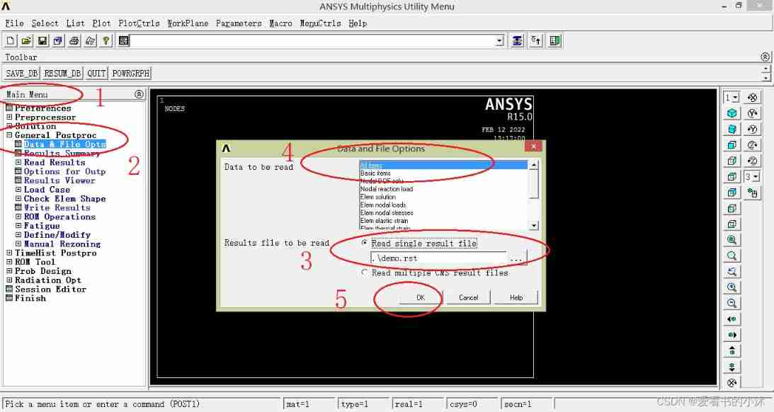
(1)GUI:General Postproc - Data&File Opts, open Data and File Options Dialog box , stay Results file to be read Choose... Later Read single result file, Click the Browse button to find the result file to be read . stay Data to be read Select the result item to be read , Click on OK Read the result file .
(2) command :FILE, Fname, Ext
Fname: file name ( Including paths ), Default to current path , Current project name ;
Ext: File extension , Such as RST、RTH、RMG wait .
3.7 Main processing module
| name | function | Menu path | command |
|---|---|---|---|
| prep7 | Build a geometric model , Give material properties , Dividing the network and imposing boundary conditions | Main Menu > Preprocessor | /prep7 |
| solution | load 、 solve | Main Menu > Solution | /solu |
| post1 | Check the calculation result at a certain time | Main Menu > General Postproc | /post1 |
| post26 | View the calculation results on the time history | Main Menu > TimeHist Postproc | /post26 |
| pds | Probabilistic design | Main Menu > Prob Design | /pds |
| aux2 | Turn binary files into readable files | Utility Menu > File>List>Binary Files… | /aux2 |
| aux12 | Calculate the radiation factor and matrix in thermal analysis | Main Menu > Radiation Opt | /aux12 |
| aux15 | from CAD or FEM Transfer files in the program | Utility Menu > File > Import | /aux15 |
3.8 Basic operation process
ANSYS The main steps of using are as follows : Preliminary confirmation 、 Before processing ( Modeling and meshing )、 Apply load to solve 、 post-processing ( View results ).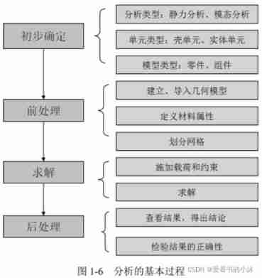
The post-processing instructions are as follows :
(1) General post-processing module POST1
Used to watch the results of the whole model at a certain time .( Such as : Photos of the results “snapshot”).
Click... In the utility menu item “General Postproc” Option to enter the general post-processing module . This module can display and output the previous analysis results in graphical form . for example , The result of the calculation is ( Such as stress ) The changes in the model can be represented by contour map , Different contour colors , Represents different values ( Such as stress value ). The intensity chart uses different colors to represent different value areas ( Such as stress range ), It clearly reflects the regional distribution of the calculation results .
(2) Time history response post-processing module POST26
It is used to watch the results of the model in different time periods or load steps , It is often used to deal with the results of transient analysis and dynamic analysis .
Click... In the utility menu item TimeHist Postpro Option to enter the time history response post-processing module . This module is used to check the results in a time period or sub step process , Such as node displacement 、 Stress or reaction . These results can be viewed by drawing curves or lists . Draw a curve of one or more variables varying with frequency or other quantities , It helps to visualize the analysis results . in addition ,POST26 You can also perform algebraic operations on curves .
Through a friendly user interface , It is easy to obtain the calculation results of the solution process and display them . These results may include displacement 、 temperature 、 Stress 、 Strain 、 Speed and heat flow , The output form can be graphic display and data list .
The post-processing module can display the calculation results in color contour 、 Gradient display 、 Vector display 、 Particle flow trace display 、 Stereoscopic slice display 、 Transparent and translucent display ( You can see inside the structure ) And so on , The calculation results can also be shown in charts 、 Display or output in curve form .
3.9 Secondary development function
ANSYS Is a very powerful general finite element analysis software .
ANSYS The input mode of can be generally divided into menu mode 、 Command mode 、 Macro mode 、 Function mode 、 Document method, etc . From the perspective of use, it can be divided into two categories , namely GUI(Graphical User Interface) Mode and command flow mode .
ANSYS Implementation analysis is usually divided into two kinds :
- GUI operation , The advantage is that the operation is intuitive , Getting started is easier ;
- Based on parametric language APDL(Ansys Parametric Design Languange) The operation of , The advantage is that it is easy to modify 、 It is convenient for parameterization and process analysis , Especially in the stage of product scheme design, it has great advantages .
ANSYS It also provides users with the following three ways to expand the function of secondary development tools :
- Parametric design language (ANSYS Parametric Design Language,APDL),
ANSYS Data interface : Main and CAD Software Association , Realize the seamless connection of design and analysis 、 and FORTRAN、MATLAB and VC++ And other programming software to achieve joint simulation analysis . - User interface design language (User Interface Design Language,UIDL), Mainly used to develop featured GUI The user interface , Such as the output window of some data ;
- User programmable features (User Programmable Features,UPFs), It is mainly used to customize the material constitutive 、 Failure criteria 、 Unit type and Optimization Algorithm ;
among , The first two can be classified as standard use characteristics , The latter is a non-standard use feature .
Some special industry or engineering problems , It will involve secondary development , and APDL Language is the foundation of secondary development .
4、APDL Command specification ( part )
Ansys Classic platforms and workbench platform .
4.1 SET
SET, Lstep, Sbstep, Fact, KIMG, TIME, ANGLE, NSET, ORDER
Defines the data set to be read from the results file.
| Parameter values | describe |
|---|---|
| N | Read load step N. |
| FIRST | Read the first data set (Sbstep and TIME are ignored). |
| LAST | Read the last data set (Sbstep and TIME are ignored). |
| NEXT | Read the next data set (Sbstep and TIME are ignored). If at the last data set, the first data set will be read as the next. |
| PREVIOUS | Read the previous data set (Sbstep and TIME are ignored). If at the first data set, the last data set will be read as the previous. |
| NEAR | Read the data set nearest to TIME (Sbstep is ignored). If TIME is blank, read the first data set. |
| LIST | Scan the results file and list a summary of each load step. (KIMG, TIME, ANGLE, and NSET are ignored.) |
4.2 NSEL
NSEL, Type, Item, Comp, VMIN, VMAX, VINC, KABS
Selects a subset of nodes.
- NSEL, STAT
Display the current select status. - NSEL, ALL
Restore the full set. - NSEL, NONE
Unselect the full set.
4.2 /SHOW
- /SHOW, TERM
- /SHOW, png
4.3 /UIS
/UIS, Label, VALUE
Controls the GUI behavior.
- /UIS, MSGPOP
| Parameter values | describe |
|---|---|
| 0 | All messages displayed. |
| 1 | Only notes, warnings, and errors displayed. |
| 2 | Only warnings and errors displayed (default). |
| 3 | Only errors displayed. |
- /UIS, POWER
| Parameter values | describe |
|---|---|
| 0 | Start GUI in Full Graphics mode. |
| 1 | Start GUI in PowerGraphics mode (default). |
4.4 /CWD
/CWD, DIRPATH
Changes the current working directory.
4.5 FILE
FILE, Fname, Ext, –
Specifies the data file where results are to be found.
If Fname is blank, the extension defaults to RST (for structural, fluid, or coupled-field analyses), to RTH (for thermal or electrical analyses), or to RMG (for magnetic analyses). For postprocessing contact results corresponding to the initial contact state in POST1, use the RCN extension.
5、APDL Secondary development
ANYS There are two ways to work ,GUI Graphical user interface (GraphicalUser Interface Also called graphical user interface ) Operation and command flow .
ANYS Command flow mode , The fusion GUI The way 、APDL、UPFs、UIDL、MAC, even to the extent that TCL/TK In a text file , It can be done by /input command ( or UtilityMenu>File>Read Input From) Read in and execute , You can also copy the contents of this file and paste it into the command line to execute . Generally, the circulation of orders is often by ANSYS Command and APDL Functional statements consist of .
APDL The full name is ANSYS Parametric Design Language, It's also called ANSYS Parametric design language .APDL It is used to automatically complete some functions or modeling, similar to FORTRAN The explanatory language of , Provide the functions of general programming language . It contains three aspects : Toolbars 、 Parameters and macro commands .
APDL The application of is mainly reflected in that users can use programming language to ANSYS Orders are organized , Write a parameterized user program , So as to realize the whole process of finite element analysis , That is to establish parameterized CAD Model 、 Parameterized mesh generation and control 、 Parametric material definition 、 Parameterized load and boundary condition definitions 、 Parametric analysis, control and solution as well as parametric post-processing .
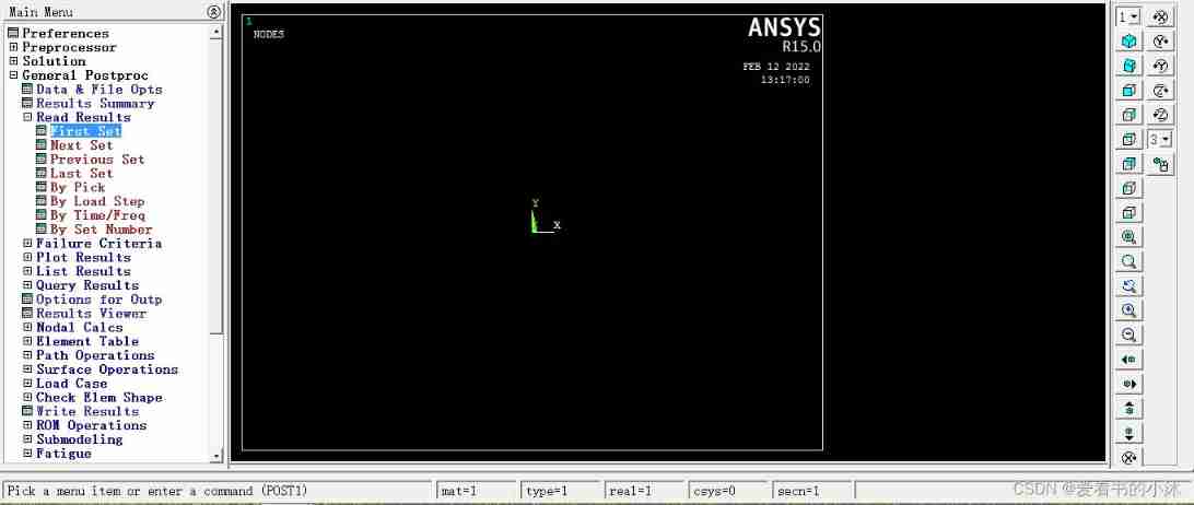
The steps of reading results in post-processing are generally :
- General Postproc -> Data and File Options, take RST Read the result file .
- Use Read Results, You can look at last step, If there are many steps in it , Press first step,next step Look at the results .
- List the results using List Results.
5.1 Load the result file ( post-processing )
- APDL The interface operation is as follows :
- APDL The command code is as follows :
finish
/post1
/cwd, d:/test
file, demo.rst
set, first
allsel
nsel, stat
eplot !  or  gplot、nplot、 kplot
/view, 1, 1,1,1
/replot
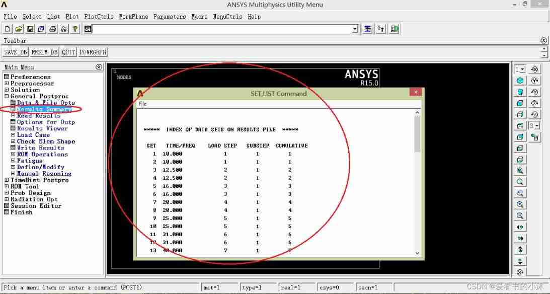
5.2 Check the overall situation of the result data ( post-processing )
APDL The related operations of the interface are as follows :
Read the first load step :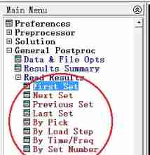
Read a load step :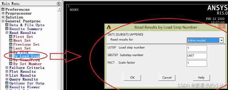
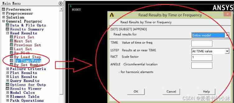
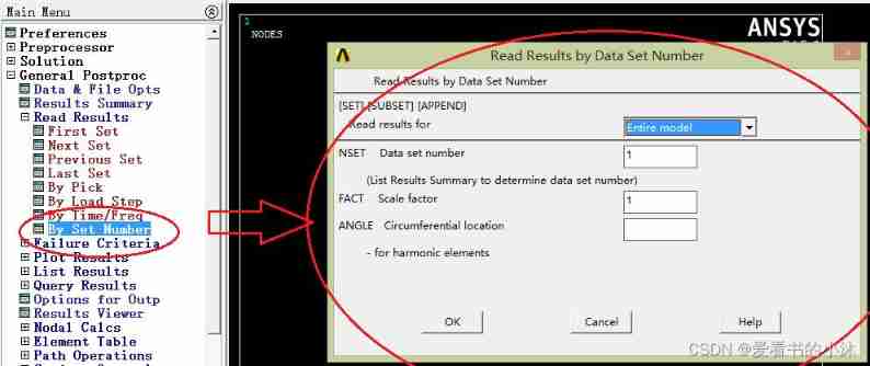
APDL The relevant code of the command is as follows :
(1) Pop-up window , And list the basic information , At the same time, list the title of each load step .
set, list
(2) Read the solution result of a load step or a sub step
set,list,0  perhaps  set,list,1  Read the result file , And list the basic information of each load step
set,list,2                       Read the result file , And list the basic information , At the same time, list the title of each load step
set,first  Read the first load step from the result file
set,last  Read the last load step from the result file
set, next  Read the next load step from the result file
set, previous  Read the previous load step from the result file
set,near,,,time  Read the load step closest to this time from the result file
set, next, 3  Read the third sub step of the next load step from the result file `
5.3 Draw the result graph ( post-processing )
APDL The related interface operations are as follows :
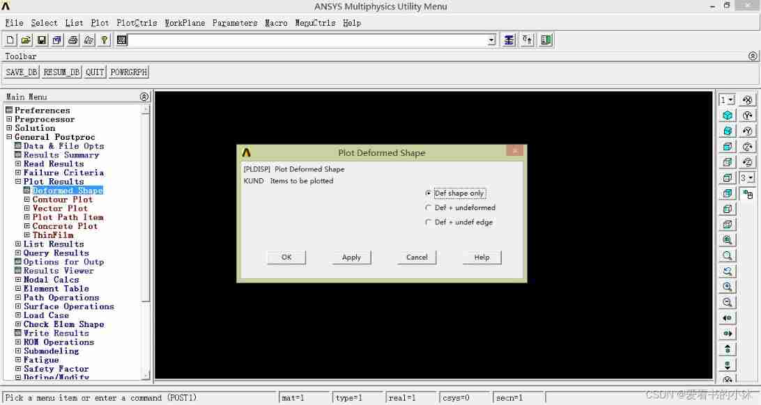
Draw the default unit diagram :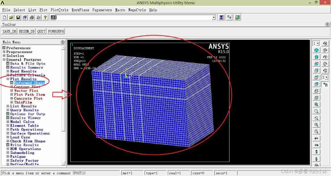
Draw the displacement contour map of the node :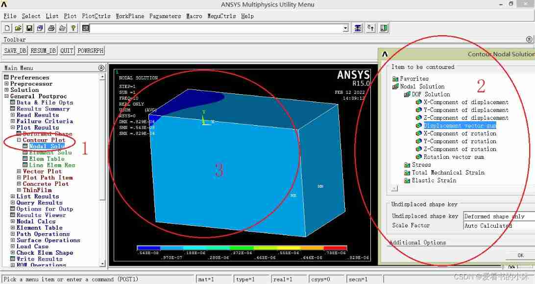
Draw the displacement contour map of the element :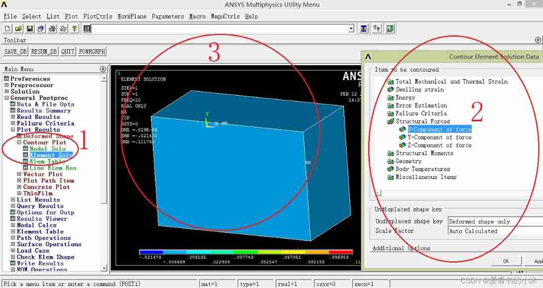
Draw a vector diagram of displacement :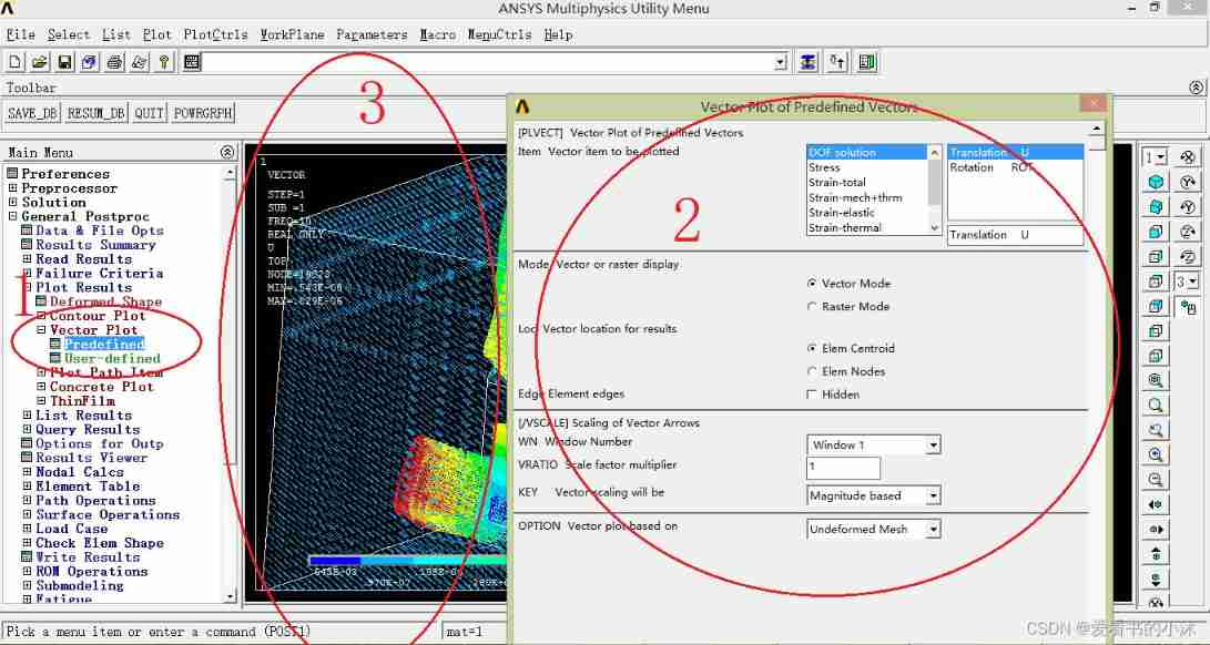
Only draw the unit diagram :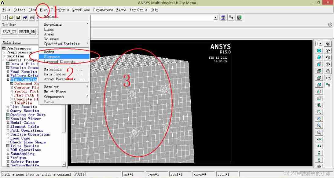
Only draw node graph :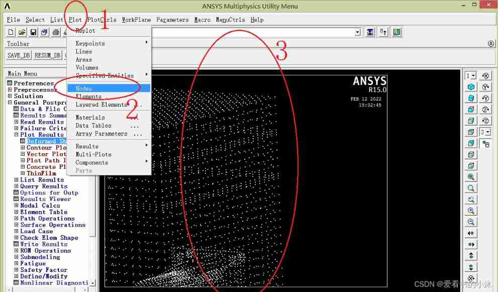
APDL The relevant code of the command is as follows :
eplot !  or  gplot、nplot、 kplot
/view, 1, 1,1,1
/replot
explain :
gplot: Comprehensive display of all elements
kplot: Show selected keys
lplot: Display the selected line
aplot: Display the selected face
vplot: Display the selected body
nplot: Display the selected node
eplot: Display the selected cell
plnsol,u,x
plnsol,u,y
plnsol,u,z
plnsol,u,sum

plesol,u,x
plesol,u,y
plesol,u,z
plesol,u,sum

plvect,u $ plvect,s

/contour,,18,-16,,500
5.4 Output animation ( post-processing )
APDL The related interface operations are as follows :
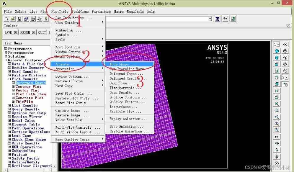
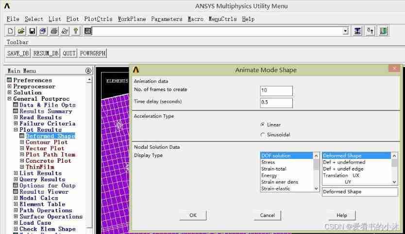
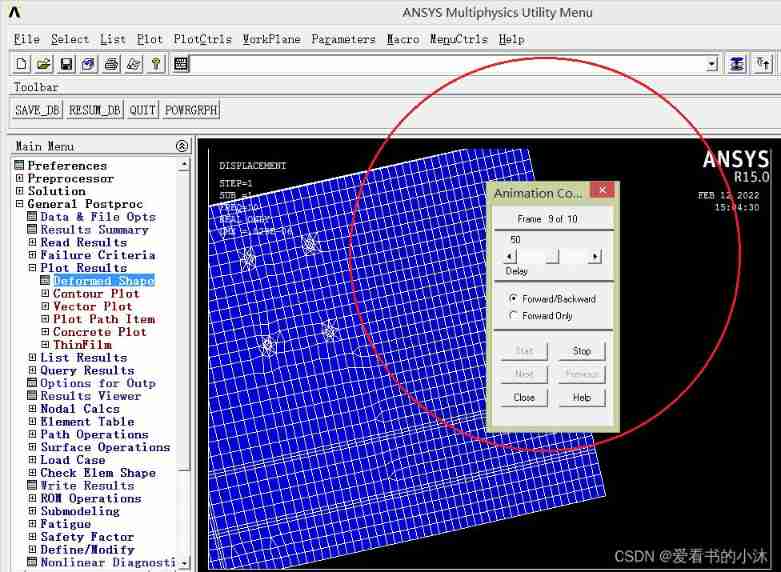
APDL The relevant code of the command is as follows :
set,first
pldisp,0
anmode,10,0.5e-1
5.5 Get the data of all nodes ( post-processing )
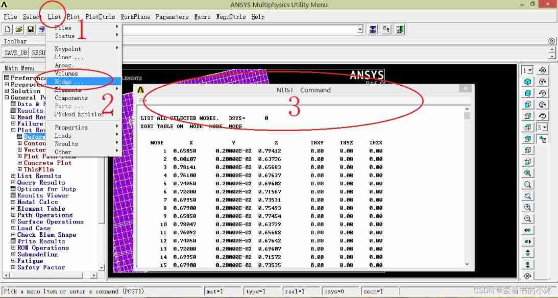
- command :NLIST
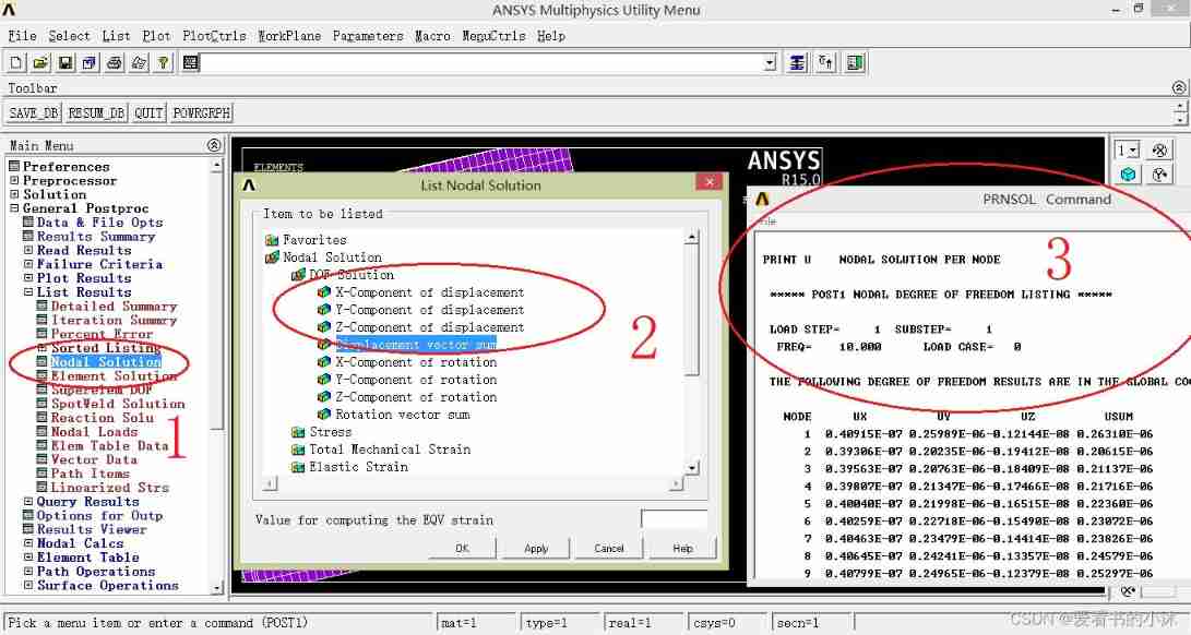
- command :PRNSOL, U, SUM
APDL The relevant code of the command is as follows :
- Method 1:
/UIS, MSGPOP, 3
allsel
*cfopen, get_nodedata, txt

!****************************************
! (1)  Get the number of nodes
*get, node_max, NODE, 0, NUM, MAX
*get, node_min, NODE, 0, NUM, MIN
*get, node_count, NODE, 0, COUNT

*vwrite, node_min
("Node 's Min Index: ", 3X, f10.0)
*vwrite, node_max
("Node 's Min Index: ", 3X, f10.0)
*vwrite, node_count
("Node 's Count: ", 3X, f10.0)
*vwrite
('title = id, X, Y, Z')

!****************************************
! (2)  Traversing and writing files
*do, i, node_min, node_max
xx=NX(i)
yy=NY(i)
zz=NZ(i)
*vwrite,'NODE', i,xx,yy,zz
(1X, a, 3X, 1f8.0, 3f16.8)
*enddo
!****************************************

*cfclose
- Method 2:
!****************************************
! (2)  Traversing and writing files
*del,nodepos
*dim,nodepos,ARRAY,node_max,3

*do,i, node_min, node_max
*get,nodepos(i,1),NODE,i,LOC,X
*get,nodepos(i,2),NODE,i,LOC,Y
*get,nodepos(i,3),NODE,i,LOC,Z
*enddo

*vwrite,sequ,nodepos(1,1),nodepos(1,2),nodepos(1,3)
(f8.0, 3f16.8)
!****************************************
- Method 3:
!****************************************
! (2)  Traversing and writing files
*do, i, node_min, node_max

*get,xx,NODE,i,LOC,X
*get,yy,NODE,i,LOC,Y
*get,zz,NODE,i,LOC,Z

*get,axy,NODE,i,ANG,XY
*get,ayz,NODE,i,ANG,YZ
*get,azx,NODE,i,ANG,ZX

*vwrite,'NODE', i,xx,yy,zz
(1X, a, 3X, 1f8.0, 3f16.8)
*enddo
- Method 4:
!****************************************
! (2)  Traversing and writing files
*do, i, node_min, node_max

*get,uxx,NODE,i,U,X
*get,uyy,NODE,i,U,Y
*get,uzz,NODE,i,U,Z
*get,usum,NODE,i,U,SUM

*get,rxx,NODE,i,ROT,X
*get,ryy,NODE,i,ROT,Y
*get,rzz,NODE,i,ROT,Z
*get,rsum,NODE,i,ROT,SUM

*vwrite,'NODE', i,uxx,uyy,uzz,usum,rxx,ryy,rzz,rsum
(1X, a, 3X, 1f8.0, 8f16.8)
*enddo
!****************************************

5.6 Get the data of all units ( post-processing )
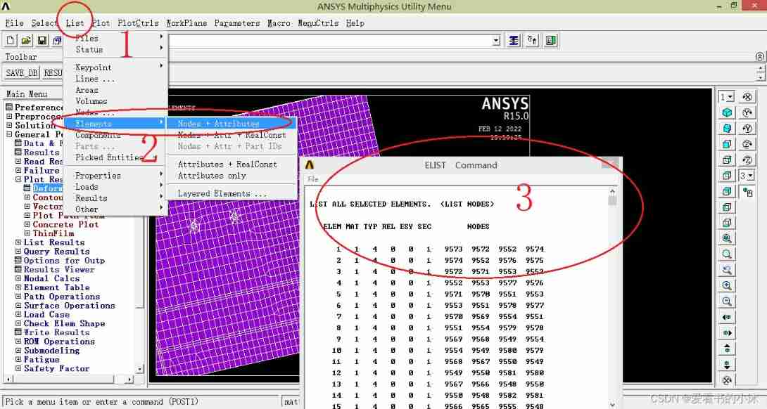
- command :ELIST
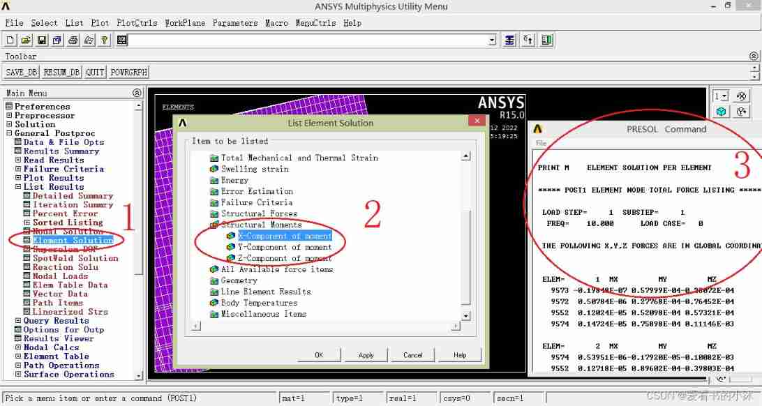
- command :PRESOL, M
- command :PRESOL, CENT
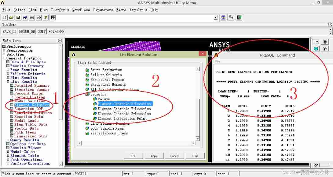
APDL The relevant code of the command is as follows :
/UIS, MSGPOP, 3
allsel
*cfopen, get_elemdata, txt

!****************************************
! (1)  Get the number of units
*get, elem_max, ELEM, 0, NUM, MAX
*get, elem_min, ELEM, 0, NUM, MIN
*get, elem_count, ELEM, 0, COUNT

*vwrite, elem_min
("Elem 's Min Index: ", 3X, f10.0)
*vwrite, elem_max
("Elem 's Min Index: ", 3X, f10.0)
*vwrite, elem_count
("Elem 's Count: ", 3X, f10.0)
*vwrite
('title = id, X, Y, Z, AREA')

!****************************************
! (2)  Traversing and writing files
*do, i, elem_min, 100
*get, ex, ELEM, i, CENT, X
*get, ey, ELEM, i, CENT, Y
*get, ez, ELEM, i, CENT, Z
*get, earea, ELEM, i, AREA

*vwrite,'ELEM', i,ex,ey,ez,earea
(1X, a, 3X, 1f8.0, 4f16.8)
*enddo

!****************************************
*cfclose

5.7 Get the data of all nodes and cells ( post-processing )
*get,nodenum,node,,num,max
*dim,nodepos,array,nodenum,3

*do,i,1,nodenum,1
*get,nodepos(i,1),node,i,loc,x
*get,nodepos(i,2),node,i,loc,y
*get,nodepos(i,3),node,i,loc,z
*enddo

*get,elemnum,elem,,num,max
*dim,elemlist,array,elemnum,6

*do,i,1,elemnum,1
*do,ii,1,6,1
*get,elemlist(i,ii),elem,i,node,ii
*enddo
*enddo

*cfopen,geomfile,txt

*vwrite,0
(F8.0,'node data:')

*vwrite,sequ,nodepos(1,1),nodepos(1,2),nodepos(1,3)
(F8.0,3f16.8)

*vwrite,0
(F8.0,'element data:')

*vwrite,sequ,elemlist(1,1),elemlist(1,2),elemlist(1,3),elemlist(1,4),elemlist(1,5),elemlist(1,6)
(F8.0,6f8.0)

*vwrite,0
(F8.0)

*cfclos
5.8 Obtain node and cell data at all frequency time points ( post-processing )
!ernorm, off
!/rmdir, 'results'
!/mkdir, 'results'

outname = 'results/dlist'
/output,%outname%,txt,
dlist

outname = 'results/elist'
/output,%outname%,txt,
elist

outname = 'results/nlist'
/output,%outname%,txt,
nlist

outname = 'results/ecent'
/output,%outname%,txt,
/format,,f,15,8
presol,cent

!*do,i,1,60,1
!set,,,,,,,i
*do,i,1,30,1
set,i,last
/format,,f,15,10
/output

outname = 'results/prnsol/t'
outname = strcat(outname, chrval(i))
/output,%outname%,txt,
prnsol,u,sum

outname = 'results/presol_m/t'
outname = strcat(outname, chrval(i))
/output,%outname%,txt,
presol,m

*enddo
/output
Postscript
If you think the method or code is a little useful , You can praise the author ;╮( ̄▽ ̄)╭
If you don't feel good about the method or code //(ㄒoㄒ)//, Just leave a message in the comments , The author continues to improve .o_O???
Thank you, children's shoes ( ´ ▽´ )ノ ( ´ ▽´)っ!!!
边栏推荐
- $refs: get the element object or sub component instance in the component:
- Implementing data dictionary with JSP custom tag
- Interviewer: what development models do you know?
- I failed in the postgraduate entrance examination and couldn't get into the big factory. I feel like it's over
- Precise space-time travel flow regulation system - ultra-high precision positioning system based on UWB
- Role of virtual machine
- BGP experiment (1)
- Asynchronous components and suspend (in real development)
- Advanced level of C language (high level) pointer
- Sqlmap tutorial (IV) practical skills three: bypass the firewall
猜你喜欢
2、 Concurrent and test notes youth training camp notes
ROS2规划系统plansys2简单的例子

普通测试年薪15w,测试开发年薪30w+,二者差距在哪?

Outlier detection technology of time series data
云备份项目
Fast quantitative, abbkine protein quantitative kit BCA method is coming!

Calculus key and difficult points record part integral + trigonometric function integral

Abnova circulating tumor DNA whole blood isolation, genomic DNA extraction and analysis
外包干了四年,废了...
Tencent's one-day life
随机推荐
Abnova membrane protein lipoprotein technology and category display
普通测试年薪15w,测试开发年薪30w+,二者差距在哪?
MIPS uclibc cross compile ffmpeg, support g711a encoding and decoding
Redis data migration
Stockage et pratique des données en langage C (haut niveau)
js小练习
Détailler le bleu dans les tâches de traduction automatique
抽丝剥茧C语言(高阶)指针进阶练习
Kuboard can't send email and nail alarm problem is solved
一、Go知识查缺补漏+实战课程笔记 | 青训营笔记
How to reduce inventory with high concurrency on the Internet
Wechat applet full stack development practice Chapter 3 Introduction and use of APIs commonly used in wechat applet development -- 3.10 tabbar component (I) how to open and use the default tabbar comp
Academic report series (VI) - autonomous driving on the journey to full autonomy
transform-origin属性详解
Flexible layout (II)
IP address
Outsourcing for four years, abandoned
How to * * labelimg
JS small exercise ---- time sharing reminder and greeting, form password display hidden effect, text box focus event, closing advertisement
电商常规问题part1
