当前位置:网站首页>FLIR blackfly s usb3 industrial camera: how to use counters and timers
FLIR blackfly s usb3 industrial camera: how to use counters and timers
2022-07-07 02:15:00 【The moon shines on the silver sea like a dragon】
Flir Blackfly S USB3 Industrial camera : How to use counters and timers
This document provides an overview of Blackfly S How to use the counter and timer in the camera .
Blackfly S Adopt the advanced ice shape sensor in the industry .
It's powerful , You can easily generate the exact image you need , And accelerate application development .
Including image capture and Automatic and precise manual control of camera preprocessing .
Blackfly S Provide GigE、USB3、 Suit and board versions .
Accurate image SONY CMOS Choices among sensors include : Global shutter 、 Polarization and high sensitivity BSI sensor .
The physical drawing is as follows :
The concept is introduced
Counter and timer functions can be realized :
- Create a function generator
- Record the number of times the signal is triggered
Some general applications include :
- Input to logical block
- External signal output is used to control external devices
- Track the number of camera exposures
- Track the number of external input signal triggers
- Trigger the camera in a predefined time period
** Be careful :** Use SpinView Application to demonstrate the configuration and execution of counter and timer control .
Configure counter and timer control
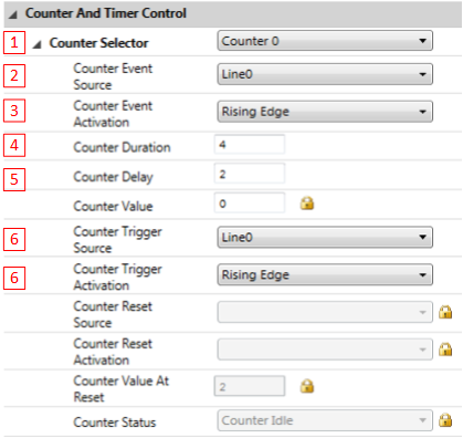
The following description corresponds to the red box serial number above
- 1. Select counter Counter 0 perhaps Counter 1
- 2. Select the signal source triggered by counter increase For example, in the picture Line0
- 3. Trigger events include low level trigger 、 High level trigger 、 Falling edge trigger 、 Rising edge trigger 、 Arbitrary edge trigger
- 4. Set the number of counter delays , To represent several counts to trigger the counter start event
- 5. Design the number of counter durations , To indicate that the timer end event is triggered after several counts
- 6. Select the signal source that controls the opening of the counter
Select the trigger event that controls the start of the counter
The level sources of triggering events can include the following :
- Trigger signal with fixed frequency
- Line input
- User output
- Counter start event
- Counter end event
- Logic module output
- Exposure begins
- The exposure is over
- Frame trigger wait
The status of the counter can be changed from nodemap Get active or idle
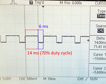
produce PWM(Pulse Width Modulation) Routine for
The goal of the example is to achieve a 50hz Duty ratio 70% Of PWM The signal
First step Set up GPIO The connection of the mouth
The first step is to set the output from the camera PWM Signal hardware . For this routine , Use an oscilloscope to display this signal .
Camera's GPIO The definition of mouth varies greatly according to the model of camera .
Blackfly S (BFS) Is defined as follows :
BFS The camera has a 6 Pin GPIO mouth . It includes a non isolated output pin and an optically isolated output pin
If you use this optical isolation pin to output ( This routine is ), The camera needs a pull-up resistor to enhance PWM The signal .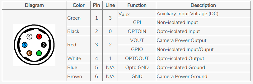
Configure hardware camera output PWM need :
- 1 Connected to the camera pin 4 Pin ( White line , Optical isolation output ) To the signal input end of the oscilloscope
- 2 Connected to the camera pin 5 Pin ( The blue line , Light isolation GND) To the ground signal of the oscilloscope
Configure the pull-up resistor to enhance the signal :
- 1 Connect a 10kΩ One end of the resistor to the camera pin 3 Pin ( The red line ,3.3v Output )
- 2 Connect the other end of this resistor to the camera pin 4 Pin ( White line , Optical isolation output )
- 3 Connected to the camera pin 6 ( Brown thread ,GND) To the camera pin 5 ( The blue line , Light isolation GND)
Second parts Set up the upper computer software (SpinView)
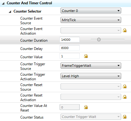
The following section shows how to SpinView Set in PWM
1 Select a counter Counter 0 perhaps Counter 1
2 Select in counter events MHz Tick It stands for 1MHz The signal of
3 In order to establish 50Hz The periodic signal of , Need to set up Counter Duration by 20000 The calculation is 1MHz/50Hz=20000 cycles/duration
4 Definition Counter Duration and Counter Delay To establish 70% Duty cycle of
The calculation method is Counter Delay = 30% x 20,000 = 6,000
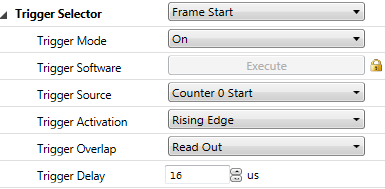
Counter Duration = 70% x 20,000 = 14,0005 stay Counter Trigger Source Choose from FrameTriggerWait, Then set the Counter Trigger Activation by Level High
6 prohibit Exposure Auto, Set up Exposure Time Less than 1/50 s
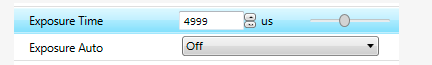
7 Can make Trigger Mode choice Trigger Source by Counter0 Start
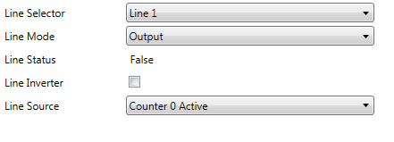
8 To configure GPIO bring Line1 by Output. then Line Source by Counter 0 Active
9 Can make 3.3V Of line ( The red line )
10 You can see the configuration through the oscilloscope PWM Output
Routine to detect the number of missing triggers
Number of lost triggers = Total triggers - Number of exposures
adopt Counter0 Count Total number of triggers
adopt Counter1 Count Number of exposures
The method is as follows :
- 1 prohibit Exposure Auto And set a longer Exposure Time such as 3.5s
- 2 Can make Trigger Mode And set up Trigger Source by line0 Rising edge
- 3 Connect Line0 To the camera
- 4 To configure Counter 0 Count the number of triggers :Counter Event Source choice Line 0 ,Counter Event Activation Set up Rising Edge, then Trigger Source choice Line0 ,Counter Trigger Activation choice Rising Edge, Last Counter Duration Is a larger value ,Counter Delay by 0

- 5 To configure Counter 1 To record the number of exposures
First Set up Counter Event Source by ExposureStart, Set up Counter Event Activation by Rising Edge
then Set up Counter Trigger Source by ExposureStart, Set up Counter Trigger Activation by Rising Edge
Last Counter Duration Is a larger value ,Counter Delay by 0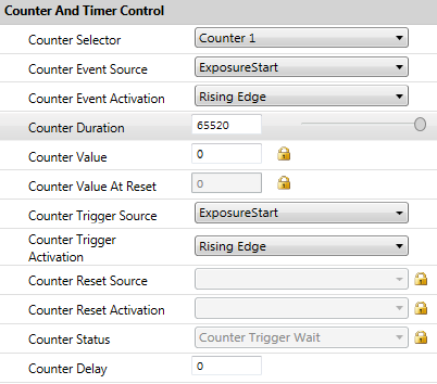
- 6 Can make 1Hz The trigger source of , The camera starts taking pictures
- 7 stay SpinView In the right , Refresh , such Counter Value The specific value will be displayed
see Counter0 Of Counter Value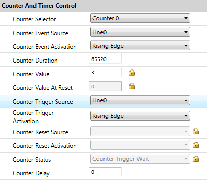
And then choose Counter 1 , Write down the value of the counter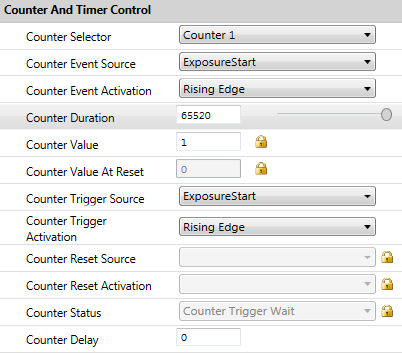
- 8 Finally, calculate the loss trigger
Namely Counter0 Value – Counter1 Value Value 3-1 by 2.
边栏推荐
- Zabbix 5.0:通过LLD方式自动化监控阿里云RDS
- Word wrap when flex exceeds width
- freeswitch拨打分机号源代码跟踪
- Unicode string converted to Chinese character decodeunicode utils (tool class II)
- 3D激光SLAM:Livox激光雷达硬件时间同步
- Golang foundation - data type
- @Before, @after, @around, @afterreturning execution sequence
- 组合导航:中海达iNAV2产品描述及接口描述
- Decryption function calculates "task state and lifecycle management" of asynchronous task capability
- Flir Blackfly S USB3 工业相机:计数器和定时器的使用方法
猜你喜欢
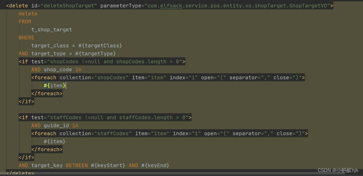
Batch delete data in SQL - set in entity
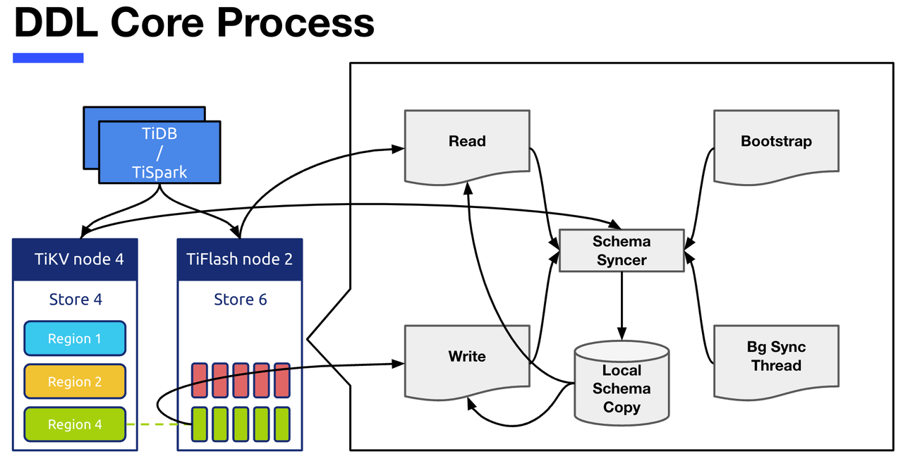
Tiflash source code reading (IV) design and implementation analysis of tiflash DDL module
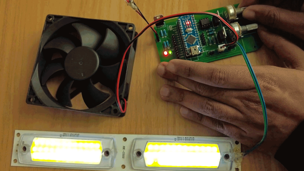
Make DIY welding smoke extractor with lighting

张平安:加快云上数字创新,共建产业智慧生态
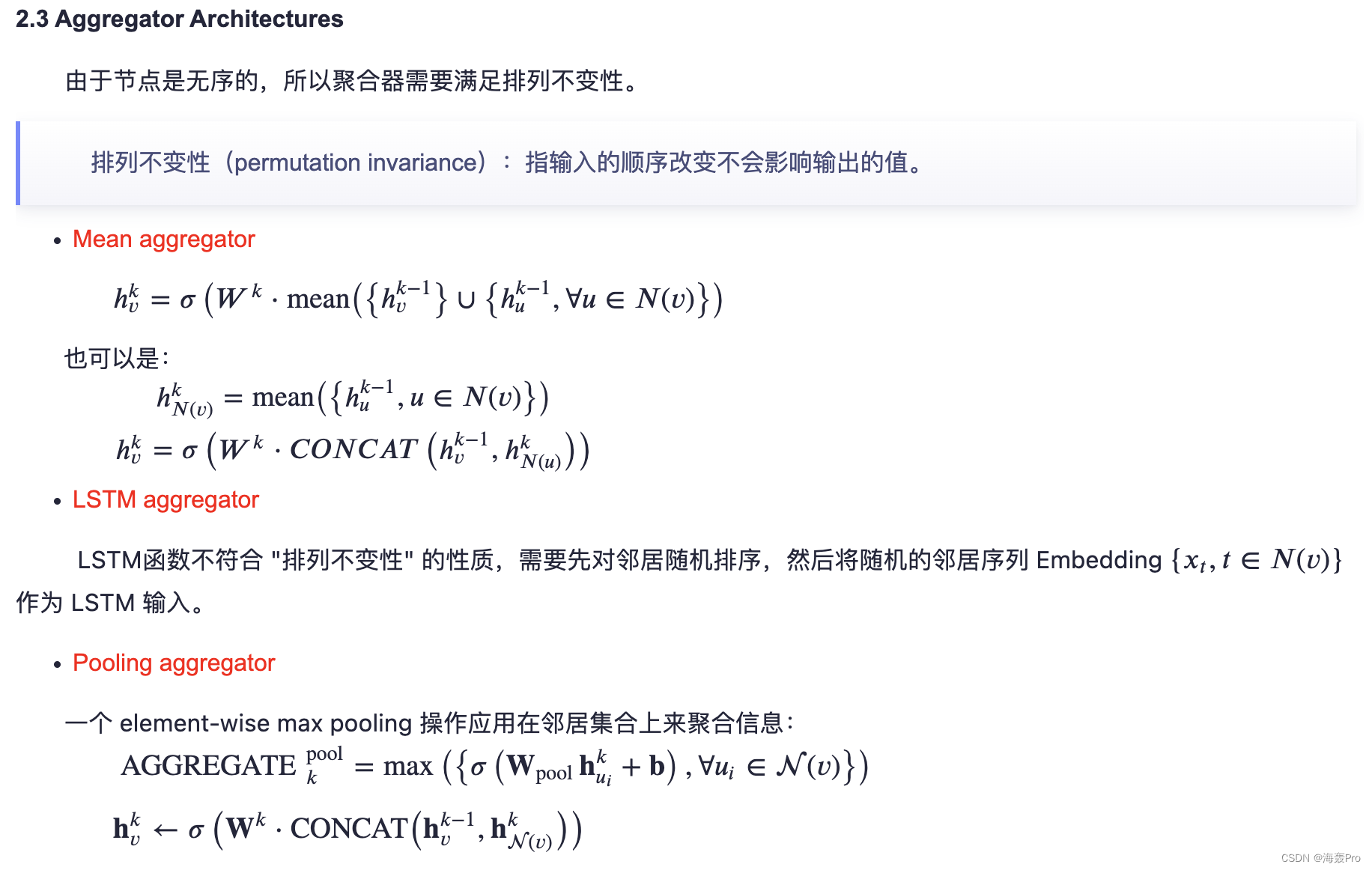
【论文阅读|深读】 GraphSAGE:Inductive Representation Learning on Large Graphs

Flir Blackfly S 工业相机:通过外部触发实现多摄像头同步拍摄
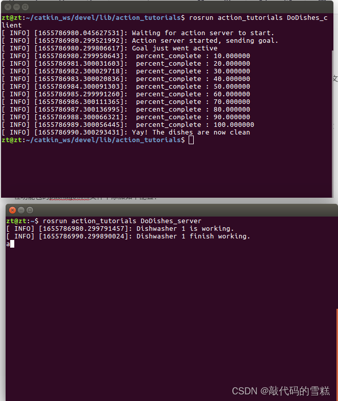
ROS學習(23)action通信機制
ROS学习(21)机器人SLAM功能包——orbslam的安装与测试
Cisp-pte practice explanation (II)
ROS学习(25)rviz plugin插件
随机推荐
Halcon knowledge: segment_ contours_ XLD operator
新一代云原生消息队列(一)
Zhang Ping'an: accelerate cloud digital innovation and jointly build an industrial smart ecosystem
TiFlash 源码阅读(四)TiFlash DDL 模块设计及实现分析
The last line of defense of cloud primary mixing department: node waterline design
处理streamlit库上传的图片文件
将截断字符串或二进制数据
Sensor: introduction of soil moisture sensor (xh-m214) and STM32 drive code
RC振荡器和晶体振荡器简介
MetaForce原力元宇宙开发搭建丨佛萨奇2.0系统开发
SchedulX V1.4.0及SaaS版发布,免费体验降本增效高级功能!
一片葉子兩三萬?植物消費爆火背後的“陽謀”
解密函数计算异步任务能力之「任务的状态及生命周期管理」
Unicode string converted to Chinese character decodeunicode utils (tool class II)
【唯一】的“万字配图“ | 讲透【链式存储结构】是什么?
ROS learning (25) rviz plugin
Centos8 install MySQL 8.0 using yum x
freeswitch拨打分机号源代码跟踪
2022/0524/bookstrap
Flir Blackfly S USB3 工业相机:白平衡设置方法