当前位置:网站首页>Learning record: Tim - capacitive key detection
Learning record: Tim - capacitive key detection
2022-07-06 15:24:00 【Bitter tea seeds】
Catalog
One 、 Principle of capacitive key
1.1、 Touch the capacitive button without fingers
1.2、 There are fingers touching the capacitive button
1.3、Vc Relationship between voltage and charging time
2.2、 Check the specific process of pressing the capacitive button
Preface
( Reference resources 《 Wildfire reference manual 》)
Capture function through input , To make a capacitive touch button . use TIM5 The passage of 2(PA1) For input capture , And realize a simple capacitive touch button , Through this key control DS1 On and off .
Capacitive buttons do not require any external mechanical components , Easy to use , The cost is low , It is easy to make a keyboard sealed with the surrounding environment , In order to play the role of moisture prevention . The outstanding advantages of capacitive keys make more and more electronic products use it to replace the traditional mechanical keys .
One 、 Principle of capacitive key
Capacitor ( It is called capacitance for short ) It's a device that can hold charge , A layer of insulator between two metal blocks can form the simplest capacitor . There are two pieces of metal , There is an insulating medium between , This forms a capacitor . Such a capacitor is very easy to realize on the circuit board , Generally, the copper pieces around the design are connected with the signal of the circuit board , Such a structure is the model of capacitive buttons . When the shape of the circuit board is fixed , The capacity of the capacitor is also relatively stable .

When making circuit boards, an insulating layer will be covered on the surface , For corrosion protection and insulation , So the actual circuit board design situation As shown in the figure, there is no finger touch . The top layer of the circuit board is insulating material , The next layer is conductive copper foil , According to the circuit routing Design determines the shape of copper foil , The next floor is usually FR-4 board . There is insulating material between the metal sensor and the ground signal , The whole can be equivalent to a capacitor Cx. Usually when designing , The metal sensor is designed to be convenient for fingers to touch .
1.1、 Touch the capacitive button without fingers
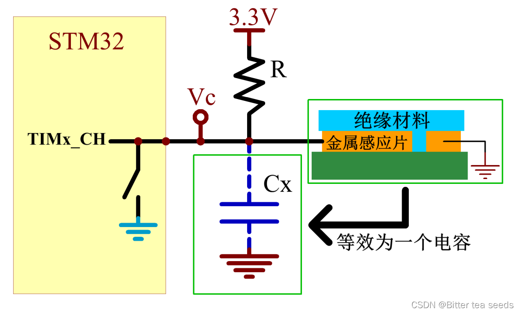
When the circuit board is not powered on , It can be considered that capacitance  There is no charge , On power up , Under the action of resistance , capacitance
  There will be a charging process , Until the capacitor is full , namely
  The voltage value is 3.3V, The length of this charging process is affected by resistance R Resistance and capacitance
  Direct influence of capacitance . But in choosing the right resistance R After welding and fixing to the circuit board , This charge Time will basically not change , Because at this time, the resistance R It's fixed , capacitance
  It is basically unchanged without obvious external interference .
1.2、 There are fingers touching the capacitive button
When we touch with our fingers , In addition to forming an equivalent capacitance with the ground signal  Outside , It will also form a
  Equivalent capacitance .
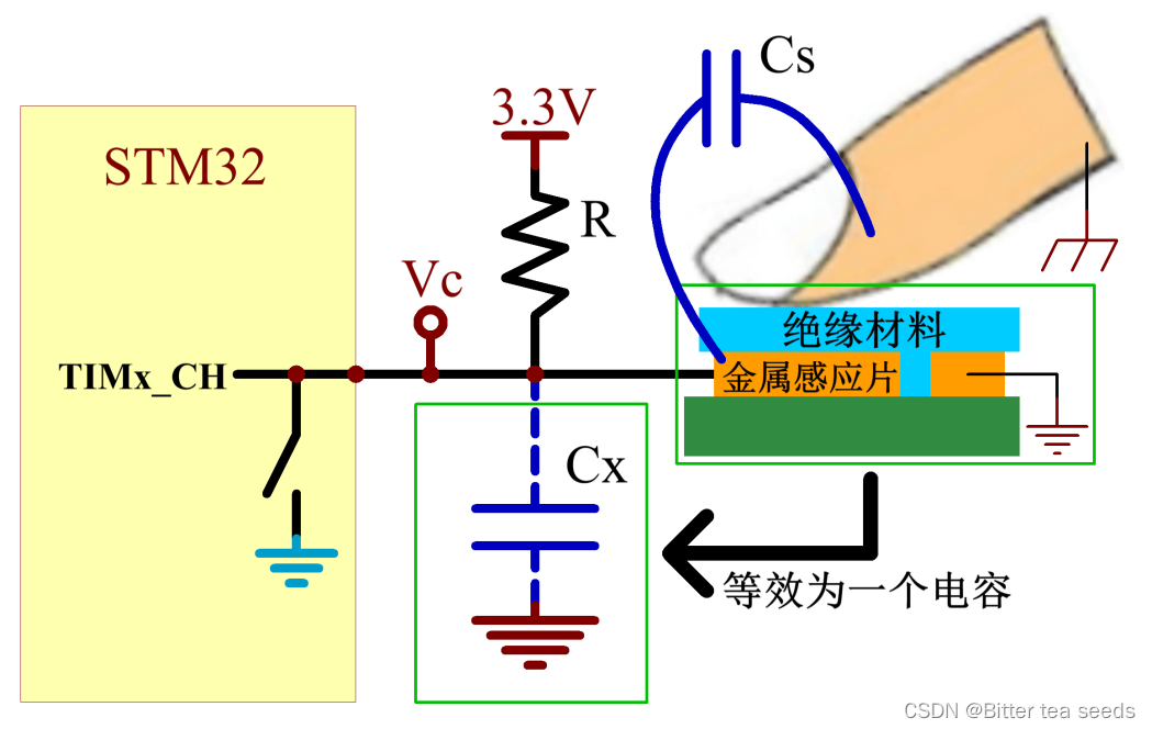
At this time, the whole capacitive button can hold more charge than when there is no finger touch , It can be seen as  and
and  The effect of stacking . At the same resistance R Under the circumstances , Because the capacitance value increases , This leads to a longer charging time . That is, the longer the charging time makes us distinguish whether there is finger touch , That is, whether the capacitive button is pressed .
The main task is to measure the charging time . The charging process can be seen as a signal from low level to high level cheng , Now is the time to ask for this change process . We can use the timer input capture function to calculate the charging time , namely Set up TIMx_CH Enter the capture mode channel for the timer . In this way, the charging time without touch is measured first as the reference , Then periodically measure the charging time and compare it with the charging time without touch , If it exceeds a certain threshold, it is considered that there is a finger touch .
1.3、Vc Relationship between voltage and charging time
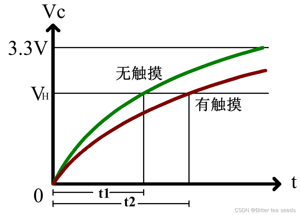
To measure the charging time , You need to set the timer input capture function to trigger the rising edge , In the figure VH Is the voltage value of the triggered rising edge , It's also STM32 It is considered as the lowest voltage value of high level , about 1.8V.
t1 and t2 It can be captured by timer / Compare registers to get .
Before measuring the charging time , To make this charging process . There will be a charging process when the circuit board is powered on , Now it is required to cycle through the keys while the program is running , Therefore, the generation of charging process must be controlled . Can be controlled TIMx_CH Pin as ordinary GPIO Use , Make it output low level for a short period of time , For capacitance Cx discharge , namely Vc by 0V. When reconfigured TIMx_CH Is the capacitance at the time of input capture Cx In resistance R The charging process can be produced under the action of .
Two 、 Programming
2.1、 Design thinking
(1) Write timer input capture correlation function (2) Measure the no-load charging time of the capacitor button T1(3) Measure the charging time when the capacitive button is touched by hand T2(4) Just compare T2 And T1 Time to detect whether the key is touched by fingers
2.2、 Check the specific process of pressing the capacitive button
- TPAD The pin is set to push-pull output , Output 0, Discharge the capacitor to 0.
- TPAD The pin is set to float input (IO The state after reset ), The capacitor starts charging .
- At the same time open TPAD The input capture of the pin starts to capture .
- Wait for the charge to complete ( Charging to the end Vx, Rising edge detected ).
- Calculate the charging time .
2.3、 Project code
tpad.c The code is as follows :
#include "tpad.h"
#include "delay.h"
#include "usart.h"

#define TPAD_ARR_MAX_VAL 	0XFFFF	// maximal ARR value
vu16 tpad_default_val=0;// When it's empty ( No hands pressed ), The time the counter takes


// Initialize touch button
// Get the value of touch button when empty .
// Return value :0, Successful initialization ;1, initialization failed
u8 TPAD_Init(u8 psc)
{
	u16 buf[10];
	u16 temp;
	u8 j,i;
	TIM5_CH2_Cap_Init(TPAD_ARR_MAX_VAL,psc-1);// With 1Mhz Frequency count of
	for(i=0;i<10;i++)// Read continuously 10 Time
	{
		buf[i]=TPAD_Get_Val();
		delay_ms(10);
	}
	for(i=0;i<9;i++)// Sort
	{
		for(j=i+1;j<10;j++)
		{
			if(buf[i]>buf[j])// Ascending order
			{
				temp=buf[i];
				buf[i]=buf[j];
				buf[j]=temp;
			}
		}
	}
	temp=0;
	for(i=2;i<8;i++)temp+=buf[i];// Take the middle one 6 Average the data
	tpad_default_val=temp/6;
	printf("tpad_default_val:%d\r\n",tpad_default_val);
	if(tpad_default_val>TPAD_ARR_MAX_VAL/2)return 1;// Initialization encountered more than TPAD_ARR_MAX_VAL/2 The numerical , Is not normal !
	return 0;
}
// Reset once
void TPAD_Reset(void)
{
  	GPIO_InitTypeDef  GPIO_InitStructure;
	RCC_APB2PeriphClockCmd(RCC_APB2Periph_GPIOA, ENABLE);	 // Can make PA Port clock

	// Set up GPIOA.1 To push and pull
 	GPIO_InitStructure.GPIO_Pin = GPIO_Pin_1;				 //PA1  port configuration
 	GPIO_InitStructure.GPIO_Mode = GPIO_Mode_Out_PP; 		 // Push pull output
 	GPIO_InitStructure.GPIO_Speed = GPIO_Speed_50MHz;
 	GPIO_Init(GPIOA, &GPIO_InitStructure);
 	GPIO_ResetBits(GPIOA,GPIO_Pin_1);						 //PA.1 Output 0, discharge

	delay_ms(5);

	TIM_SetCounter(TIM5,0);		// return 0
	TIM_ClearITPendingBit(TIM5, TIM_IT_CC2|TIM_IT_Update); // Clear interrupt flag
	// Set up GPIOA.1 Enter... For the float
	GPIO_InitStructure.GPIO_Mode=GPIO_Mode_IN_FLOATING;	 // Floating input
	GPIO_Init(GPIOA, &GPIO_InitStructure);


}
// Get the timer capture value
// If the timeout , Then it directly returns the count value of the timer .
u16 TPAD_Get_Val(void)
{
	TPAD_Reset();
	while(TIM_GetFlagStatus(TIM5, TIM_IT_CC2) == RESET)// Wait for the rising edge to capture
	{
		if(TIM_GetCounter(TIM5)>TPAD_ARR_MAX_VAL-500)return TIM_GetCounter(TIM5);// It's overtime , Go straight back to CNT Value
	};
	return TIM_GetCapture2(TIM5);
}
// Read n Time , Taking the maximum
//n: The number of consecutive acquisitions
// Return value :n The maximum reading value read in the second reading
u16 TPAD_Get_MaxVal(u8 n)
{
	u16 temp=0;
	u16 res=0;
	while(n--)
	{
		temp=TPAD_Get_Val();// Get a value
		if(temp>res)res=temp;
	};
	return res;
}
// Scan touch button
//mode:0, Continuous triggering is not supported ( You have to release it once to press it again );1, Support continuous trigger ( You can press it all the time )
// Return value :0, Didn't press ;1, There is a press ;
#define TPAD_GATE_VAL 	100	// Threshold of touch , That is, it must be greater than tpad_default_val+TPAD_GATE_VAL, It's effective touch .
u8 TPAD_Scan(u8 mode)
{
	static u8 keyen=0;	//0, You can start testing ;>0, We can't start testing yet
	u8 res=0;
	u8 sample=3;		// The default number of samples is 3 Time
	u16 rval;
	if(mode)
	{
		sample=6;		// When you support multi click , Set the sampling number to 6 Time
		keyen=0;		// Support to click
	}
	rval=TPAD_Get_MaxVal(sample);
	if(rval>(tpad_default_val+TPAD_GATE_VAL))// Greater than tpad_default_val+TPAD_GATE_VAL, It works
	{
		if(keyen==0)res=1;		//keyen==0, It works
		//printf("r:%d\r\n",rval);
		keyen=3;				// At least again 3 The key will not be valid until after
	}
	if(keyen)keyen--;
	return res;
}
// Timer 2 passageway 2 Input capture configuration
void TIM5_CH2_Cap_Init(u16 arr,u16 psc)
{
	GPIO_InitTypeDef  GPIO_InitStructure;
   	TIM_TimeBaseInitTypeDef  TIM_TimeBaseStructure;
	TIM_ICInitTypeDef  TIM5_ICInitStructure;

	RCC_APB1PeriphClockCmd(RCC_APB1Periph_TIM5, ENABLE);	 // Can make TIM5 The clock
	RCC_APB2PeriphClockCmd(RCC_APB2Periph_GPIOA, ENABLE);	 // Can make PA Port clock
	// Set up GPIOA.1 Enter... For the float
	GPIO_InitStructure.GPIO_Pin = GPIO_Pin_1;				 //PA1  port configuration
 	GPIO_InitStructure.GPIO_Speed = GPIO_Speed_50MHz;	// Speed 50MHz
   	GPIO_InitStructure.GPIO_Mode=GPIO_Mode_IN_FLOATING;	 // Floating input
	GPIO_Init(GPIOA, &GPIO_InitStructure);	 // Set to float input

   	// initialization TIM5
	TIM_TimeBaseStructure.TIM_Period = arr; // Set the counter to automatically reload
	TIM_TimeBaseStructure.TIM_Prescaler =psc; 	// Preassigned frequency counter
	TIM_TimeBaseStructure.TIM_ClockDivision = TIM_CKD_DIV1; // Set the clock split :TDTS = Tck_tim
	TIM_TimeBaseStructure.TIM_CounterMode = TIM_CounterMode_Up;  //TIM Upcount mode
	TIM_TimeBaseInit(TIM5, &TIM_TimeBaseStructure); // according to TIM_TimeBaseInitStruct The parameter specified in TIMx Unit of time base
	// Initialize channel 2
  	TIM5_ICInitStructure.TIM_Channel = TIM_Channel_2; //CC1S=01 	 Select input  IC2 Mapping to TI5 On
  	TIM5_ICInitStructure.TIM_ICPolarity = TIM_ICPolarity_Rising;	// Rising edge capture
  	TIM5_ICInitStructure.TIM_ICSelection = TIM_ICSelection_DirectTI;
  	TIM5_ICInitStructure.TIM_ICPrescaler = TIM_ICPSC_DIV1;	 // Configure the input divider , Regardless of the frequency
  	TIM5_ICInitStructure.TIM_ICFilter = 0x03;//IC2F=0011  Configure input filter  8 A timer clock cycle filter
  	TIM_ICInit(TIM5, &TIM5_ICInitStructure);// initialization I5 IC2

    TIM_Cmd(TIM5,ENABLE ); 	// Enable timer 5
}
tpad.h The code is as follows :
#ifndef __TPAD_H
#define __TPAD_H
#include "sys.h"

extern vu16 tpad_default_val;

void TPAD_Reset(void);
u16  TPAD_Get_Val(void);
u16 TPAD_Get_MaxVal(u8 n);
u8   TPAD_Init(u8 psc);
u8   TPAD_Scan(u8 mode);
void TIM5_CH2_Cap_Init(u16 arr,u16 psc);
#endif
main.c The code is as follows :
#include "led.h"
#include "delay.h"
#include "key.h"
#include "sys.h"
#include "usart.h"
#include "tpad.h"

 int main(void)
 {
 	u8 t=0;
	delay_init();	    	 // Delay function initialization
	NVIC_PriorityGroupConfig(NVIC_PriorityGroup_2);// Set up NVIC Interrupt grouping 2:2 Bit preemption priority ,2 Bit response priority
	uart_init(115200);	 // The serial port is initialized to 115200
 	LED_Init();			     //LED Port initialization
  TPAD_Init(6);			// Initialize touch button
   	while(1)
	{
 		if(TPAD_Scan(0))	// Successfully captured a rising edge ( This function takes at least 15ms)
		{
			LED1=!LED1;		//LED1 Take the opposite
		}
		t++;
		if(t==15)
		{
			t=0;
			LED0=!LED0;		//LED0 Take the opposite , Prompt program is running
		}
		delay_ms(10);
	}
 }
边栏推荐
- 如何成为一个好的软件测试员?绝大多数人都不知道的秘密
- Mysql database (II) DML data operation statements and basic DQL statements
- MySQL development - advanced query - take a good look at how it suits you
- Brief introduction to libevent
- Leetcode simple question: check whether two strings are almost equal
- What if software testing is too busy to study?
- Sorting odd and even subscripts respectively for leetcode simple problem
- Servlet
- Réponses aux devoirs du csapp 7 8 9
- ucore Lab 1 系统软件启动过程
猜你喜欢
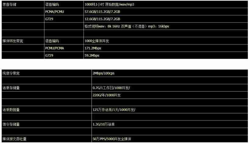
Description of Vos storage space, bandwidth occupation and PPS requirements
软件测试面试要问的性能测试术语你知道吗?

Sorting odd and even subscripts respectively for leetcode simple problem
基于485总线的评分系统双机实验报告
Do you know the performance testing terms to be asked in the software testing interview?
Servlet
How to become a good software tester? A secret that most people don't know

Nest and merge new videos, and preset new video titles
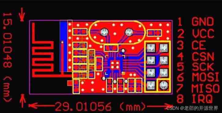
Portapack application development tutorial (XVII) nRF24L01 launch B
ucore lab 2
随机推荐
Description of Vos storage space, bandwidth occupation and PPS requirements
Crawler series of learning while tapping (3): URL de duplication strategy and Implementation
UCORE LaB6 scheduler experiment report
软件测试有哪些常用的SQL语句?
ArrayList集合
Knowledge that you need to know when changing to software testing
学习记录:TIM—电容按键检测
线程及线程池
51 lines of code, self-made TX to MySQL software!
The latest query tracks the express logistics and analyzes the method of delivery timeliness
LeetCode#53. Maximum subarray sum
Réponses aux devoirs du csapp 7 8 9
Your wechat nickname may be betraying you
How to do agile testing in automated testing?
STM32学习记录:输入捕获应用
MySQL transactions
Preface to the foundations of Hilbert geometry
The most detailed postman interface test tutorial in the whole network. An article meets your needs
The maximum number of words in the sentence of leetcode simple question
Leetcode simple question: check whether the numbers in the sentence are increasing
