当前位置:网站首页>Learning record: how to perform PWM output
Learning record: how to perform PWM output
2022-07-06 15:33:00 【Bitter tea seeds】
Catalog
1.1、PWM The output mode — classification
2.1、 Channel 1 output working process
3、 ... and 、PWM Register configuration
3.1、 Capture / Compare mode register (TIMx_CCMR1/2)
3.2、 Capture / Compare enable register (TIMx_CCER)
3.3、 Capture / Compare register (TIMx_CCR1~4)
Preface
use TIM3 The passage of 2, Put the channel 2 Remap to PB5, produce PWM To control LED0 The brightness of .
One 、PWM brief introduction
Pulse width modulation (PWM),“Pulse Width Modulation” Abbreviation , abbreviation Pulse width modulation , It is a very effective technology to control analog circuit by using digital output of microprocessor . A little bit more simple , It's the control of pulse width .
and PWM Output is External output pulse width ( The duty cycle ) Adjustable square wave signal , The signal frequency is determined by the auto reload register ARR Value determination of , The duty cycle is determined by the comparison register CCR Value determination of .
STM32 In addition to TIM6、7. Other timers can be used to generate PWM Output . One of the advanced timers TIM1、TIM8 It can produce as many as 7 On the road PWM Output . And universal timers can also generate up to 4 On the road PWM Output , such ,STM32 At most... Can be generated at the same time 30 road PWM Output .
1.1、PWM The output mode — classification
PWM There are two patterns ,PWM1 and PWM2;
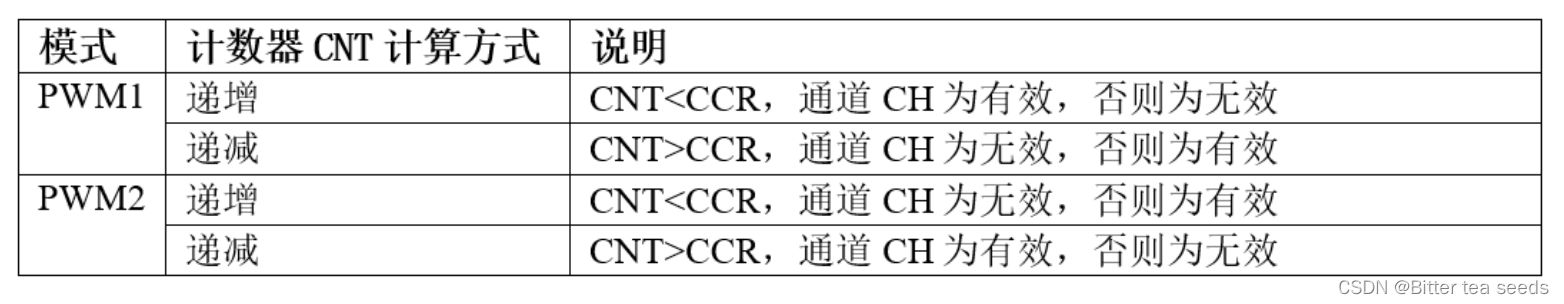
With PWM1 Pattern , Counter CNT The counting direction is also divided into edge alignment mode and center alignment mode .PWM The signal It is mainly used to control the motor , One General motor control uses edge alignment mode ,FOC The motor generally uses the center alignment mode .
Edge alignment when ,CNT Only work in increasing or decreasing . When the center is aligned ,CNT Work is increasing and decreasing .
1.2、PWM Edge alignment mode
In incremental count mode , Counter from 0 Count to auto overload value (TIMx_ARR The contents of the register ), And then again from 0 Start counting and generate counter overflow Events .
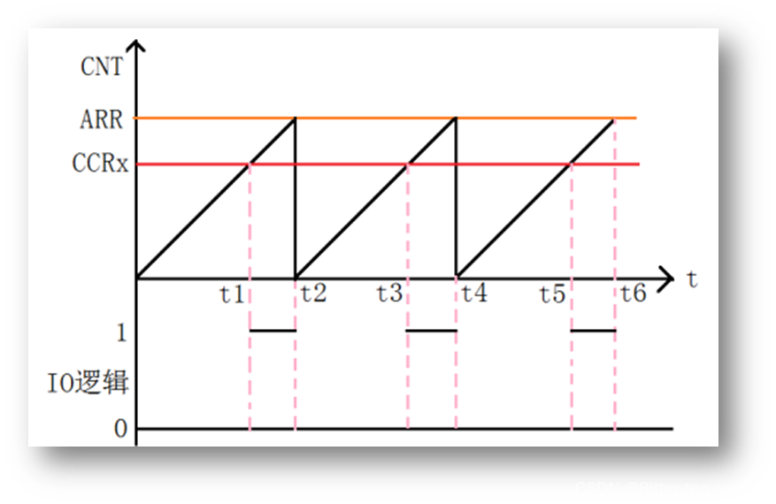
In edge alignment mode , Counter CNT Working in only one mode , Increasing or decreasing mode . With CNT Working in incremental mode, for example , In the middle ARR=8,CCR=4,CNT from 0 Start counting , When CNT<CCR The value of ,OCxREF For effective high level , At the same time , Compare interrupt registers CCxIF Set up . When CCR=CNT≤ARR when ,OCxREF Invalid low level . then CNT Again from 0 Start counting and generate counter overflow Events , And so on .
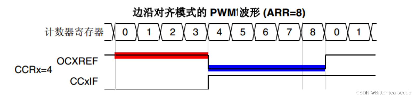
1.3、PWM Center alignment mode
In center alignment mode , Counter CNT It's a job to do / In decreasing mode . At the beginning , Counter CNT from 0 Start counting to the auto reload value minus 1(ARR-1), Generate counter overflow event ; Then count down from the auto overload value to 1 And generate counter underflow event . After from 0 Start counting again .
chart PWM1 The center of the pattern aligns the waveform yes PWM1 The center of the pattern aligns the waveform ,ARR=8,CCR=4.
The first stage counter CNT Working in incremental mode , from 0 Start counting , When CNT<CCR when ,OCxREF For effective high level , When CCR≤CNT<<ARR when ,OCxREF Invalid low level .
The second stage counter CNT Working in decrement mode , from ARR The value of begins to decrease , When CNT>CCR when ,OCxREF Is invalid low level , When CCR≥CNT≥1 when ,OCxREF For effective high level .
On the waveform, we divide the waveform into two stages :
The first stage is the counter CNT Waveforms working in incremental mode , This stage is divided into ① and ② Two phases ;
The second stage is the counter CNT Waveforms working in decreasing mode , This stage is divided into ③ and ④ Two phases .
The waveform characteristics in the center alignment mode are ① and ③ rank The period of time is equal ,② and ④ The stages are equal in time .
Center alignment patterns are divided into center alignment patterns 1、2、3, Three : Specifically, the register CR1 position CMS[1:0] To configure .
The difference is to compare the interrupt flag bit CCxIF When to place 1: Central mode 1 stay CNT Set... When decrementing the count 1, Center alignment mode 2 stay CNT Set... When counting up 1, Central mode 3 stay CNT Set... When counting up and down 1.
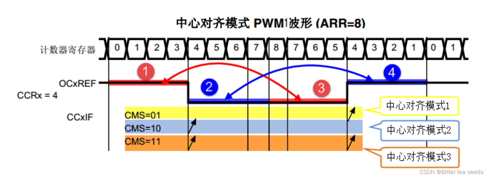
Two 、PWM working process
2.1、 Channel 1 output working process
CCR1: Capture comparison ( value ) register (x=1,2,3,4): Set the comparison value .
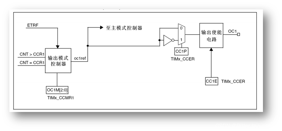
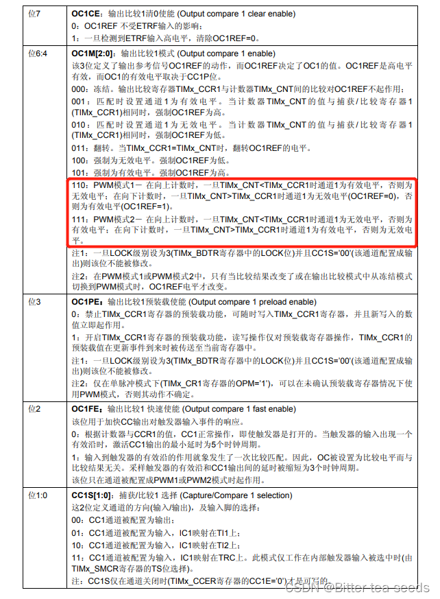
CCMR1: OC1M[2:0] position :
about PWM Under way , Used for setting up PWM Pattern 1【110】 perhaps PWM Pattern 2【111】
CCER:CC1P position : Input / Capture 1 Output polarity .0: High active ,1: Low level active .
CCER:CC1E position : Input / Capture 1 Output enable .0: close ,1: open .
3、 ... and 、PWM Register configuration
Capture / Compare mode register (TIMx_CCMR1/2)、 Capture / Compare enable register (TIMx_CCER)、 Capture / Compare register (TIMx_CCR1~4).
3.1、 Capture / Compare mode register (TIMx_CCMR1/2)
The registers are TIMx _CCMR1 and TIMx _CCMR2.TIMx_CCMR1 control CH1 and 2, and TIMx_CCMR2 control CH3 and 4.
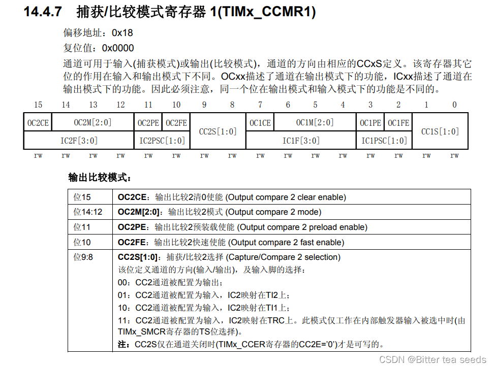
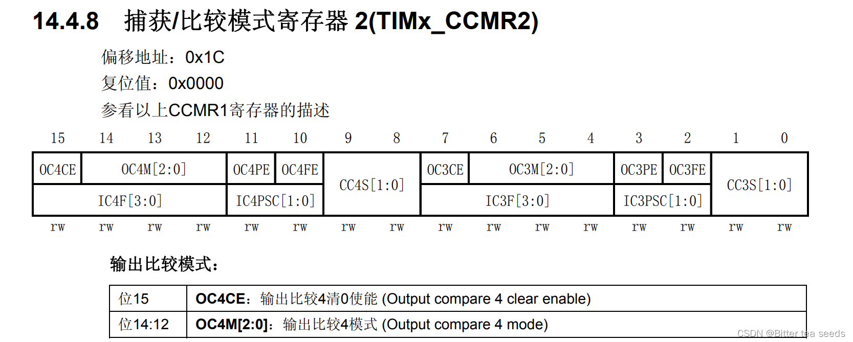
Some bits of this register are in different modes , Function differently , So in the picture 14.4.8 in , We divided the registers 2 layer , The upper layer corresponds to output and the lower layer corresponds to input .
Mode setting bit OCxM, This part is made up of 3 A composition . A total of... Can be configured 7 Patterns , We use PWM Pattern , So this 3 Bit must be set to 110/111. These two kinds of PWM The difference between modes is that the polarity of the output level is opposite .
3.2、 Capture / Compare enable register (TIMx_CCER)
This register controls the switch of each input and output channel .
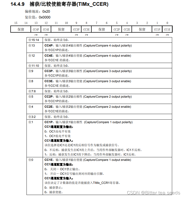
It's just... Here CC2E position , This bit is an input / Capture 2 Output enable bit , If you want to PWM from IO output , This bit must be set to 1, So we need to set this bit to 1.
3.3、 Capture / Compare register (TIMx_CCR1~4)
This register has 4 individual , Corresponding 4 Two transmission channels CH1~4; this 4 Each register is about the same .
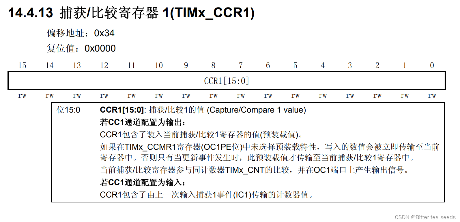
In output mode , The value of this register is the same as CNT Value comparison of , Generate corresponding actions according to the comparison results . Take advantage of this , By modifying the value of this register , You can control PWM The output pulse width of .
Four 、 Remapping function
utilize TIM3 Of CH2 Output PWM To control DS0 The brightness of , however TIM3_CH2 The default is connected to PA7 above , And ours DS0 Connect to PB5 above , If it's normal MCU, Maybe you can only use the fly wire handle PA7 Fly to PB5 Come up and realize . however STM32, You can use the remapping function , hold TIM3_CH2 Mapping to PB5 On .
STM32 The remapping control of is by reusing remapping and debugging IO Configuration register (AFIO_MAPR) The control of the
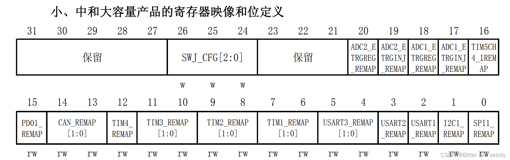
TIM3_REMAP By [11:10] this 2 Bit controlled ;
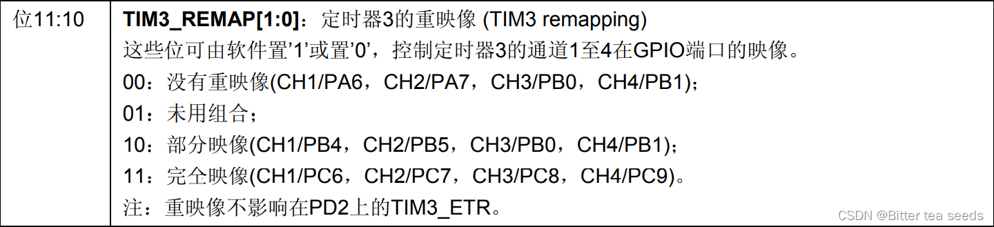
By default ,TIM3_REMAP[1:0] by 00, There is no remapping , therefore TIM3_CH1~TIM3_CH4 They are connected to PA6、PA7、PB0 and PB1 Upper , And we want TIM3_CH2 Mapping to PB5 On , You need to set TIM3_REMAP[1:0]=10, That is, partial remapping , Here we need to pay attention to , here TIM3_CH1 Also mapped to PB4 Yes .
5、 ... and 、 Programming
The output step :
1. Enable timer 3 And the related IO Port clock .
Enable timer 3 The clock :RCC_APB1PeriphClockCmd();
Can make GPIOB The clock :RCC_APB2PeriphClockCmd();
2. initialization IO The port is the output of multiplexing function . function :GPIO_Init();
GPIO_InitStructure.GPIO_Mode = GPIO_Mode_AF_PP;
3. Here we are going to PB5 Used as a timer PWM Output pin , So remap the configuration ,
So it needs to be turned on AFIO The clock . Set remapping at the same time .
RCC_APB2PeriphClockCmd(RCC_APB2Periph_AFIO,ENABLE);
GPIO_PinRemapConfig(GPIO_PartialRemap_TIM3, ENABLE);
4. Initialize the timer :ARR,PSC etc. :TIM_TimeBaseInit();
5. Initialize the output comparison parameters :TIM_OC2Init();
6. Enable preload register : TIM_OC2PreloadConfig(TIM3, TIM_OCPreload_Enable);
7. Enable timer .TIM_Cmd();
8. Constantly changing the comparison value CCRx, Achieve different duty cycle effects :TIM_SetCompare2();
Programming :
time.c file
#include "timer.h"
#include "led.h"
#include "usart.h"

/*
1, increase TIM3_PWM_Init function .
2, increase LED0_PWM_VAL Macro definition , control TIM3_CH2 Pulse width
*/
/*
 Universal timer 3 Interrupt initialization
 Here, the clock is selected as APB1 Of 2 times , and APB1 by 36M
arr: Auto reload value .
psc: Clock presplitting frequency
 Here's a timer 3!
*/

void TIM3_Int_Init(u16 arr,u16 psc)
{
		TIM_TimeBaseInitTypeDef  TIM_TimeBaseStructure;
		NVIC_InitTypeDef NVIC_InitStructure;

		RCC_APB1PeriphClockCmd(RCC_APB1Periph_TIM3, ENABLE); // Clock enable

		TIM_TimeBaseStructure.TIM_Period = arr; // Set the value of the auto reload register cycle for the next update event load activity 	  Count to 5000 by 500ms
		TIM_TimeBaseStructure.TIM_Prescaler =psc; // Set as TIMx Prescaled value of clock frequency divisor   10Khz The counting frequency of
		TIM_TimeBaseStructure.TIM_ClockDivision = 0; // Set the clock split :TDTS = Tck_tim
		TIM_TimeBaseStructure.TIM_CounterMode = TIM_CounterMode_Up;  //TIM Upcount mode
		TIM_TimeBaseInit(TIM3, &TIM_TimeBaseStructure); // according to TIM_TimeBaseInitStruct The parameter specified in TIMx Unit of time base

		TIM_ITConfig(TIM3,TIM_IT_Update,ENABLE ); // Enable to designate TIM3 interrupt , Allow update interrupt

		NVIC_InitStructure.NVIC_IRQChannel = TIM3_IRQn;  //TIM3 interrupt
		NVIC_InitStructure.NVIC_IRQChannelPreemptionPriority = 0;  // Take precedence 0 level
		NVIC_InitStructure.NVIC_IRQChannelSubPriority = 3;  // From the priority 3 level
		NVIC_InitStructure.NVIC_IRQChannelCmd = ENABLE; //IRQ The channel is energized
		NVIC_Init(&NVIC_InitStructure);  // according to NVIC_InitStruct The parameter specified in NVIC register

		TIM_Cmd(TIM3, ENABLE);  // Can make TIMx peripherals

}

/* Timer 3 Interrupt service routine */
void TIM3_IRQHandler(void)   //TIM3 interrupt
{
		if (TIM_GetITStatus(TIM3, TIM_IT_Update) != RESET) // Check the specified TIM Whether the interruption occurs or not :TIM  Interrupt source
		{
			TIM_ClearITPendingBit(TIM3, TIM_IT_Update  );  // eliminate TIMx Interrupt pending bit of :TIM  Interrupt source
			LED1=!LED1;
		}
}
/*
TIM3 PWM Partial initialization
PWM Output initialization
arr: Auto reload value
psc: Clock presplitting frequency
*/
void TIM3_PWM_Init(u16 arr,u16 psc)
{
		GPIO_InitTypeDef GPIO_InitStructure;
		TIM_TimeBaseInitTypeDef  TIM_TimeBaseStructure;
		TIM_OCInitTypeDef  TIM_OCInitStructure;


		RCC_APB1PeriphClockCmd(RCC_APB1Periph_TIM3, ENABLE);	// Enable timer 3 The clock
		RCC_APB2PeriphClockCmd(RCC_APB2Periph_GPIOB  | RCC_APB2Periph_AFIO, ENABLE);  // Can make GPIO Peripherals and AFIO Multiplexing function module clock

		GPIO_PinRemapConfig(GPIO_PartialRemap_TIM3, ENABLE); //Timer3 Partial remapping   TIM3_CH2->PB5

    // Set this pin to multiplex output function , Output TIM3 CH2 Of PWM Pulse shape 	GPIOB.5
		GPIO_InitStructure.GPIO_Pin = GPIO_Pin_5; //TIM_CH2
		GPIO_InitStructure.GPIO_Mode = GPIO_Mode_AF_PP;  // Multiplexing push pull output
		GPIO_InitStructure.GPIO_Speed = GPIO_Speed_50MHz;
		GPIO_Init(GPIOB, &GPIO_InitStructure);// initialization GPIO

    // initialization TIM3
		TIM_TimeBaseStructure.TIM_Period = arr; // Set the value of the auto reload register cycle for the next update event load activity
		TIM_TimeBaseStructure.TIM_Prescaler =psc; // Set as TIMx Prescaled value of clock frequency divisor
		TIM_TimeBaseStructure.TIM_ClockDivision = 0; // Set the clock split :TDTS = Tck_tim
		TIM_TimeBaseStructure.TIM_CounterMode = TIM_CounterMode_Up;  //TIM Upcount mode
		TIM_TimeBaseInit(TIM3, &TIM_TimeBaseStructure); // according to TIM_TimeBaseInitStruct The parameter specified in TIMx Unit of time base

	  // initialization TIM3 Channel2 PWM Pattern
		TIM_OCInitStructure.TIM_OCMode = TIM_OCMode_PWM2; // Select timer mode :TIM Pulse width modulation mode 2
		TIM_OCInitStructure.TIM_OutputState = TIM_OutputState_Enable; // Compare output enable
		TIM_OCInitStructure.TIM_OCPolarity = TIM_OCPolarity_High; // Output polarity :TIM High output polarity
		TIM_OC2Init(TIM3, &TIM_OCInitStructure);  // according to T The specified parameter initializes the peripheral TIM3 OC2

		TIM_OC2PreloadConfig(TIM3, TIM_OCPreload_Enable);  // Can make TIM3 stay CCR2 Pre loaded registers on

		TIM_Cmd(TIM3, ENABLE);  // Can make TIM3
}
timer.h The procedure is as follows :
#ifndef __TIMER_H
#define __TIMER_H
#include "sys.h"

void TIM3_Int_Init(u16 arr,u16 psc);
void TIM3_PWM_Init(u16 arr,u16 psc);
#endif
#include "led.h"
#include "delay.h"
#include "key.h"
#include "sys.h"
#include "usart.h"
#include "timer.h"

 int main(void)
 {
		u16 led0pwmval=0;
		u8 dir=1;
		delay_init();	    	 // Delay function initialization
		NVIC_PriorityGroupConfig(NVIC_PriorityGroup_2); 	 // Set up NVIC Interrupt grouping 2:2 Bit preemption priority ,2 Bit response priority
		uart_init(115200);	 // The serial port is initialized to 115200
		LED_Init();			     //LED Port initialization
		TIM3_PWM_Init(899,0);	 // Regardless of the frequency .PWM frequency =72000000/900=80Khz
   	while(1)
		{
			delay_ms(10);
			if(dir)led0pwmval++;
			else led0pwmval--;

			if(led0pwmval>300)dir=0;
			if(led0pwmval==0)dir=1;
			TIM_SetCompare2(TIM3,led0pwmval);
		}
 }
边栏推荐
- Future trend and planning of software testing industry
- Unpleasant error typeerror: cannot perform 'ROR_‘ with a dtyped [float64] array and scalar of type [bool]
- JDBC introduction
- Collection集合与Map集合
- STM32学习记录:输入捕获应用
- Pedestrian re identification (Reid) - Overview
- Mysql的事务
- STM32 learning record: input capture application
- The maximum number of words in the sentence of leetcode simple question
- 学习记录:TIM—电容按键检测
猜你喜欢
软件测试需求分析之什么是“试纸测试”
Crawler series (9): item+pipeline data storage
JS --- detailed explanation of JS DOM (IV)
![[200 opencv routines] 98 Statistical sorting filter](/img/ba/9097df20f6d43dfce9fc1e374e6597.jpg)
[200 opencv routines] 98 Statistical sorting filter
ucore lab7
Future trend and planning of software testing industry
转行软件测试必需要知道的知识
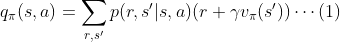
Intensive learning notes: Sutton book Chapter III exercise explanation (ex17~ex29)
UCORE lab8 file system experiment report
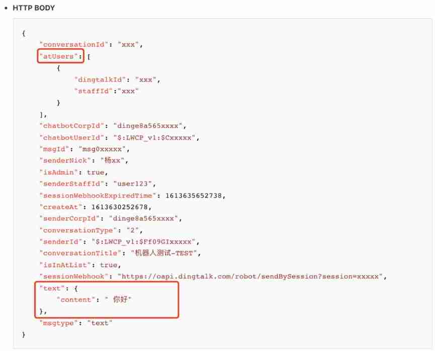
How to build a nail robot that can automatically reply


随机推荐
Future trend and planning of software testing industry
JS --- JS function and scope (II)
UCORE lab8 file system experiment report
UCORE Lab 1 system software startup process
MySQL数据库(三)高级数据查询语句
How to become a good software tester? A secret that most people don't know
线程及线程池
软件测试Bug报告怎么写?
ucore Lab 1 系统软件启动过程
Servlet
How to rename multiple folders and add unified new content to folder names
Pedestrian re identification (Reid) - data set description market-1501
软件测试面试要问的性能测试术语你知道吗?
Es6---es6 content details
How to do agile testing in automated testing?
软件测试需求分析之什么是“试纸测试”
Lab 8 文件系统
What are the software testing methods? Show you something different
Pedestrian re identification (Reid) - Overview
Mysql database (I)