当前位置:网站首页>Design of stepping motor controller based on single chip microcomputer (forward rotation and reverse rotation indicator gear)
Design of stepping motor controller based on single chip microcomputer (forward rotation and reverse rotation indicator gear)
2022-07-05 10:08:00 【Chloroplasts don't forget to breathe】
WeChat official account : Chuangxiang diary
send out : Single chip microcomputer stepping motor
Get full report +AD Schematic source file +Proteus Simulation source file + SCM source program + Related information 
One 、 Design description
1. Design purpose
Through the specific small-scale test system design , Practice the whole process of single chip microcomputer system design and debugging , To deepen the understanding of the internal structure of MCU 、 Understanding of functions and instruction systems , And further learn the application of SCM development system and the interface and programming methods of some peripheral chips , Master the hardware of single chip microcomputer system preliminarily 、 Software design technology and debugging skills .
2. The design requirements
This time I choose to finish the project 1—— Design of stepping motor controller based on MCU .
The design requirements are as follows :
1) The motor speed can be controlled smoothly ;
2) Set the speed of the motor through the button on the test box or the dial switch , to turn to ;
3) Display the speed trend of the motor ;
4) Complete basic functions : start-up / stop it , Speed up , Slow down , Positive rotation , reverse ;
5) Use the controls on the experimental box to improve the control effect and control function ( Selected as ).
3. Instruments and equipment
This experiment is conducted online , Did not go to the laboratory for hardware physical verification , Use only Proteus Software simulation .
Two 、 Hardware circuit diagram and main chip description
The single chip microcomputer selected for this system is STC89C51. The stepping motor model is 28BYJ48, The motor has four phase windings , The working voltage is +5V, It can share a power supply with the MCU . For four phase winding of stepping motor P1 Oral P1.0~P1.3 control , because P1 Insufficient mouth drive , So use one piece ULN2803 Increase driving power . Use P0 The port is connected with a light emitting diode , Used to display the current status ,P3 Port control motor forward and reverse . According to the system requirements, draw based on STC89C51 The control block diagram of stepping motor controlled by single chip microcomputer 2.1 Shown .
The system mainly includes single chip microcomputer 、 Reset circuit 、 Crystal oscillator circuit 、 Key circuit 、 Digital display circuit 、 Stepping motor and driving circuit .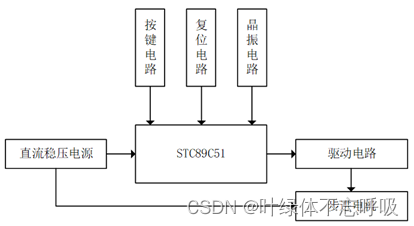
1. Minimum system circuit of single chip microcomputer
The minimum system of single chip microcomputer is the most basic and main part of the application of single chip microcomputer expansion development , It is generally composed of the following circuits , It is the core of the whole design, which ensures the expansion and Realization of other functions based on MCU . Pictured 2.2 Shown .
Reset circuit : Reset circuit is the most basic and important circuit in the application of single chip microcomputer , It is used to deal with urgent problems such as single chip microcomputer failure . When the reset port of MCU is at high level , The code in the MCU will not be executed . At the beginning of power on , The capacitor is not fully charged , Reset the port to high level , It avoids program errors caused by running the program directly after power on . When the capacitor is fully charged , The reset port becomes low , The program starts running .
Crystal oscillator circuit : Crystal oscillator circuit is also a necessary circuit in the design of MCU , Provide working sequence for the system . Crystal oscillator circuit provides 11.0592MHZ clock frequency , So as to form the whole stable oscillation circuit , Provide guarantee for the normal operation of single chip microcomputer .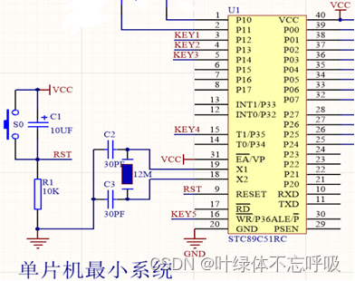
2. Digital display circuit
The nixie tube shows the electrical route 1 position 7 paragraph LED The nixie tube displays the current speed and gear ( common 9 A gear ), See the picture for details 2.3 Shown .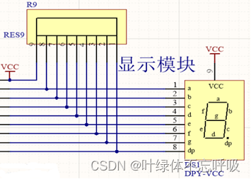
3. Key circuit
The key circuit needs to realize the key to control the forward rotation of the stepping motor 、 reverse 、 Speed up 、 Slow down 、 stop it , All in all 5 A button , See the picture for details 2.4 Shown .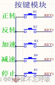
4. Motor and drive circuit
Electric motor and drive circuit ULN2003 Driver chip 、DC-5V Stepper motor 、 Revolution indicator light, etc , See the picture for details 2.5 Shown .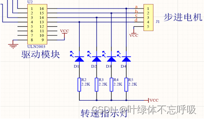
5. The overall circuit of the system 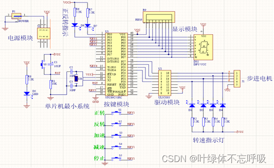
3、 ... and 、 How the system works
1. Minimum control system
Pictured 3.1, This design uses STC89C51 Single chip microcomputer , This type of single chip microcomputer is STC A low power consumption produced by the company 、 High performance CMOS8 Bit microcontroller , have 4K In system programmable Flash Memory .. On a single chip , Have dexterous 8 position CPU And in system programmability Flash, It can completely meet the needs of this design . Yes STC89C51 Single chip microcomputer , The minimum control system should generally include : Reset circuit 、 Clock circuit .
Reset circuit : The reset circuit adopts manual reset , The so-called manual reset , It refers to turning on the button switch , Make the single chip microcomputer enter the reset state .
Clock circuit : use 22pF Capacitance and 12MHz The crystal oscillator provides the clock frequency for the whole circuit . The clock signal of single chip microcomputer is usually obtained by two circuit forms : Internal oscillation mode and external interruption mode . At pin XTAL1 and XTAL2 External crystal oscillator circuit ( Crystal oscillator for short ) Or ceramic crystal oscillator , It forms the internal crystal mode . Because there is a high gain inverting amplifier inside the MCU , After the external crystal oscillator , It forms a self-excited oscillator and generates an oscillating clock pulse . The capacitance of the external circuit with internal oscillation mode is generally 5~30 pF, The typical value of crystal oscillator frequency is 12MHz, use 6MHz There are more cases .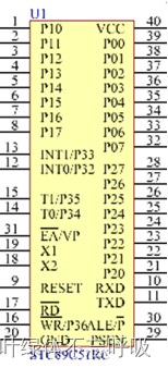
2. Drive circuit
ULN2803 High voltage and High Current Darlington transistor array , In this array 8 Ludlington transistor is a low logic level digital circuit (TTL、COMS、PMOS or NMOS) With high voltage and high current equipment ( Such as relay 、 Machine hammer 、 Light bulb: ) Ideal device for interface .ULN2803 The internal structure and external pins of the driver are shown in the figure 3.2 Shown .1-8 The foot is the input ,9 Foot joint GND,10 Pin connected load power supply +,11-18 Pin connected output . The left side of the figure below is the input ( Assuming that 1 foot ), The upper right corner is the output ( Corresponding 18 foot ),pin10 by 10 Pin connected load power supply +. When 1 Foot joint +5V When the triode is saturated , here 18 Foot output , The second triode from left to right turns on , Connect the load power GND, At this time, the load is powered on .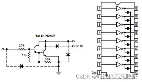
Darlington tube is also called composite tube . It is a common base combined amplifier , To form an equivalent new triode . This is equivalent to the amplification factor of the triode is the product of the two . In electronic circuit design , Darlington connection is often used in power amplifiers and regulated power supplies .
Darlington tube is a compound triode , He connected two triodes in series , The emitter of the first tube is connected to 2 The base of a tube , Therefore, the magnification of Darlington tube is the product of the magnification of two triodes . So it is characterized by very high magnification , The function of Darlington tube is generally to amplify very small signals in highly sensitive amplification circuits , Such as high-power switching circuit .
3. Stepper motor
Because the stepping angle of the stepping motor in this design is 18°, Stepping motor assembly Step Angle The default value of the property is 18, In the mode of four phases and eight beats , The step angle of each shot is 9°, Every output 8 Excitation sequence array of bytes FFW when , The motor steps in total 72°, so , Drive the motor for one revolution (360°) A common need 5 Row excitation sequence array FFW, Make the motor rotate n Circle needs to output 5n Row excitation sequence array FFW. The reverse rotation control principle of stepping motor is the same as that at this time .
Based on the above analysis , Can be designed separately STEP_MOTOR_FFW And STEP_MOTOR_REV function , They are respectively used to control the forward and reverse rotation of the stepping motor n circle , Its internal circulation is 8 Time , The external circulation is 5n Time .
choose ULN2803 As a driver chip , Through MCU P1.0P1.3 Output pulse to chip 1B4B mouth , After amplification, from 1C~4C The ports are respectively output to the A、B、C、D phase , Pictured 3.3 Shown .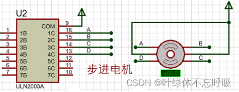
Four 、 Programming
According to the design requirements , The following specific functions need to be realized through software programming :
1) Drive each module to work , Realize the clear display of digital tube , Realize motor drive ;
2) Realize the forward rotation of the stepping motor controlled by the key 、 reverse 、 Speed up 、 Slow down 、 stop it ;
3)2 LEDs show positive and negative ,1 position 7 paragraph LED The nixie tube displays the current speed and gear ;
4)4 A red LED, Indicates the speed of the motor .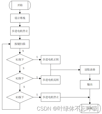
( The following is omitted , See the original report for details )
边栏推荐
- Kotlin compose and native nesting
- 分布式数据库下子查询和 Join 等复杂 SQL 如何实现?
- Data visualization platform based on template configuration
- How to use sqlcipher tool to decrypt encrypted database under Windows system
- 单片机原理与接口技术(ESP8266/ESP32)机器人类草稿
- Openes version query
- 剪掉ImageNet 20%数据量,模型性能不下降!Meta斯坦福等提出新方法,用知识蒸馏给数据集瘦身...
- Cerebral cortex: directed brain connection recognition widespread functional network abnormalities in Parkinson's disease
- Why do offline stores need cashier software?
- The essence of persuasion is to remove obstacles
猜你喜欢
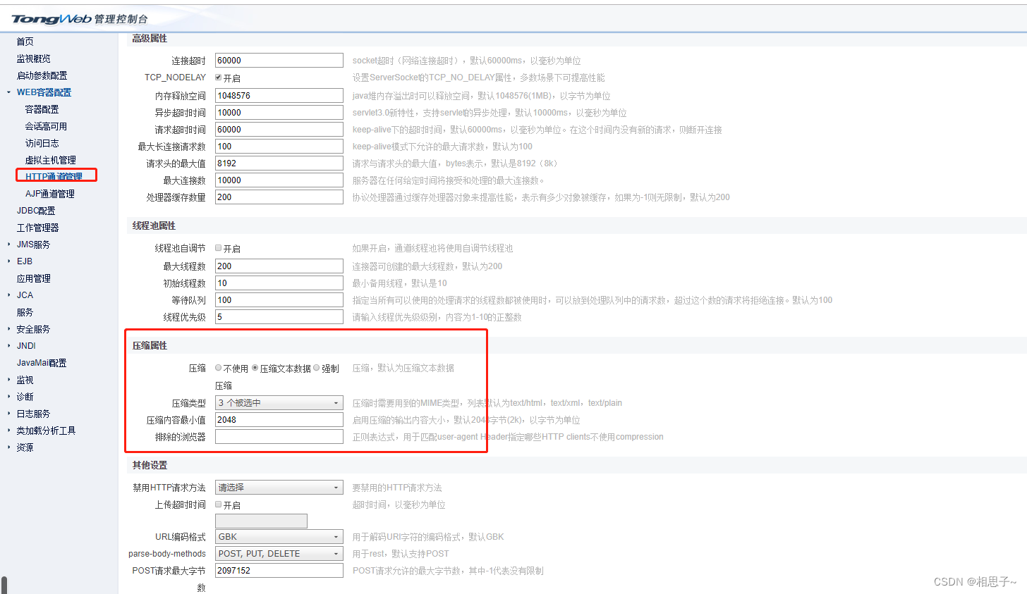
Tongweb set gzip
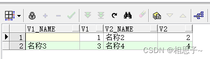
Oracle combines multiple rows of data into one row of data
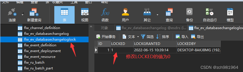
Solve liquibase – waiting for changelog lock Cause database deadlock
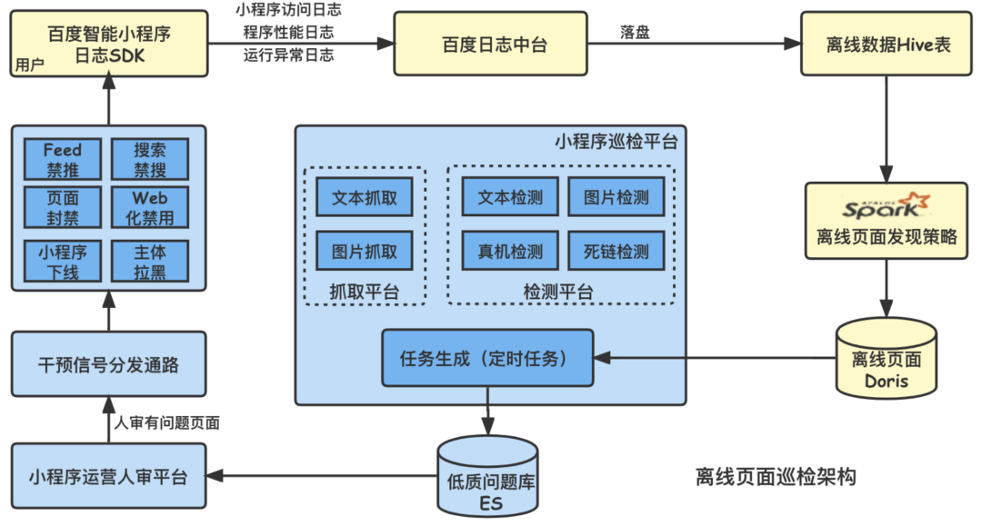
La voie de l'évolution du système intelligent d'inspection et d'ordonnancement des petites procédures de Baidu
tongweb设置gzip
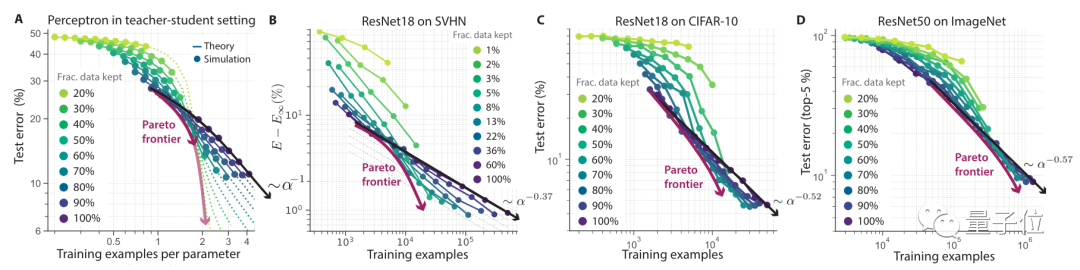
Cut off 20% of Imagenet data volume, and the performance of the model will not decline! Meta Stanford et al. Proposed a new method, using knowledge distillation to slim down the data set

苹果 5G 芯片研发失败?想要摆脱高通为时过早
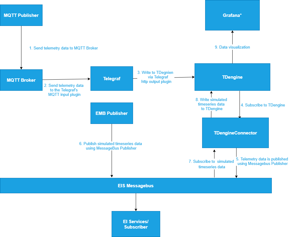
TDengine × Intel edge insight software package accelerates the digital transformation of traditional industries
oracle 多行数据合并成一行数据
解决idea调试过程中liquibase – Waiting for changelog lock….导致数据库死锁问题
随机推荐
Oracle combines multiple rows of data into one row of data
正式上架!TDengine 插件入驻 Grafana 官网
7 月 2 日邀你来TD Hero 线上发布会
Kotlin Compose 多个条目滚动
Analysis on the wallet system architecture of Baidu trading platform
90%的人都不懂的泛型,泛型的缺陷和应用场景
Kotlin compose multiple item scrolling
mysql80服务不启动
Online chain offline integrated chain store e-commerce solution
Node-RED系列(二九):使用slider与chart节点来实现双折线时间序列图
Uncover the practice of Baidu intelligent testing in the field of automatic test execution
Cerebral Cortex:有向脑连接识别帕金森病中广泛存在的功能网络异常
Flutter development: use safearea
Is it really reliable for AI to make complex decisions for enterprises? Participate in the live broadcast, Dr. Stanford to share his choice | qubit · viewpoint
QT realizes signal transmission and reception between two windows
Theme. AppCompat. Light. Darkactionbar not found
Why does everyone want to do e-commerce? How much do you know about the advantages of online shopping malls?
美图炒币半年亏了3个亿,华为被曝在俄罗斯扩招,AlphaGo的同类又刷爆一种棋,今日更多大新闻在此...
卷起来,突破35岁焦虑,动画演示CPU记录函数调用过程
一种用于干式脑电图的高密度256通道电极帽